1
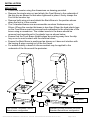
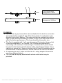
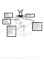
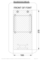
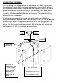
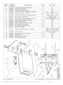
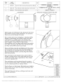
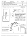
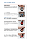
UBER FONT SERVICE MANUAL Marco Beverage Systems Ltd. 63d Heather Road, Sandyford Industrial Estate, Dublin 18, Republic of Ireland Ireland Tel: (01) 295 2674 Ireland Fax: (01) 295 3715 UK Tel: (0207) 274 4577 UK Fax: (0207) 978 8141 Service Manual 1000810 811 811US 811L 812 812L 815 816 820 821 822 822L 30-07-13.docx Page 1 of 13 CONTENTS INTRODUCTION PAGE 3 STANDARD INSTRUCTION MANUAL 4 ASSEMBLY DRAWINGS PARTS LIST 10 SWITCH REMOVAL 11 DISPENSE HEAD REMOVAL 12 Service Manual 1000810 811 811US 811L 812 812L 815 816 820 821 822 822L 30-07-13.docx Page 2 of 13 INTRODUCTION The information provided in this manual is intended to assist in the installation and maintenance of the Marco Uber Font range. Please read the instructions carefully to prevent accidents and ensure an efficient installation. This manual is not a substitute for any safety instructions or technical data affixed to the machine or its packaging. All information in this manual is current at the time of publication and is subject to change without notice. Only technicians or service providers authorised by Marco should carry out installation and maintenance of these machines. Marco accepts no responsibility for any damage or injury caused by incorrect or unreasonable installation and operation. Service Manual 1000810 811 811US 811L 812 812L 815 816 820 821 822 822L 30-07-13.docx Page 3 of 13 STANDARD INSTRUCTION MANUAL (6 PAGES) Marco Beverage Systems Ltd. INSTRUCTIONS FOR MODEL Font Uber Style Marco Beverage Systems Limited. 63d Heather Road, Sandyford Industrial Estate, Dublin 18. Marco Beverage Systems Limited. Shire House, Strixton Manor, Strixton, Wellingborough, Northants, NN29 7PA Ireland Tel: +353 (0)1 295 2674 Ireland Fax: +353 (0)1 295 3715 email: [email protected] www.marco.ie UK Tel: +44 (0)2072 744 577 UK Fax: +44 (0)2079 788 141 email: [email protected] www.marco-bev.co.uk Service Manual 1000810 811 811US 811L 812 812L 815 816 820 821 822 822L 30-07-13.docx Page 4 of 13 INSTALLATION: MOUNTING: Cutout the counter using the dimensions on drawing provided. Remove the single wing nut and attach the Front Brace to the underside of the drip tray as shown so that when tightened in place it firmly clamps the Font to the counter top. Remove both wing nuts and attach the Back Brace in the position shown when the font is in the counter. The 2 standard braces can accommodate counters thicknesses up to 55mm. Where the counter thickness is less than 30mm the hard plastic legs on the Front Brace must be removed and reattached to the other side of the brace using a screwdriver. The rubber inserts in the brace should be removed and repositioned in the plastic legs as shown below. Ensure that the Front Brace folded edges are pointing away from the drip tray so as to avoid contact with the electrical wires. Ensure the Back Brace is positioned as shown so it does not interfere with the hosing & wires coming out of the font head. For added stability a bead of silicone sealant may be applied to the underside of the tile around the perimeter. Back Brace 2 Front Brace 1 Thin Counter Thickness <30mm Swivel brace configuration Standard Counter thickness 30-55mm Standard Swivel Brace configuration Service Manual 1000810 811 811US 811L 812 812L 815 816 820 821 822 822L 30-07-13.docx Page 5 of 13 0-30mm 30-55mm Thin Counter Brace arrangement < 30mm Thick Counter swivel Brace Arrangement 30-55mm PLUMBING: The Font has a grey hose which can be attached to the boiler’s vent outlet (secured with the supplied F clip). This allows steam & condensate to be directed into the font driptray. This hose must have a constant rise with no sags or kinks which would allow an airlock to form in the line which would effect the boilers performance. The hose should be trimmed to size. The Font is supplied with 1 or 2 semi transparent Font water tubes so that it can be connected to 1 or 2 boilers. The Y piece can be removed if connecting to 2 machines. If connecting to 1 machine the Y piece should be used to direct water up both silicone tubes (see diagram below). Use a cable tie to secure the Y piece to the tank outlet. Hoses & insulation can be trimmed down to reduce heat loss, ensure there are no kinks in the tubes. If connecting to only 1 boiler unit then the 2-1 wiring adaptor kits must be used (see diagram below). The Font has a drip tray attached with a drain outlet which may be plumbed. Service Manual 1000810 811 811US 811L 812 812L 815 816 820 821 822 822L 30-07-13.docx Page 6 of 13 2- wire Electrical Connection Font to Boiler Water tube Font to boiler 2-1 Adaptors required if connecting to only one boiler Vent may be plumbed to a drain – however there must be an air gap to prevent the possibility of a blocked drain flowing into the boiler. Service Manual 1000810 811 811US 811L 812 812L 815 816 820 821 822 822L 30-07-13.docx Drip Tray Outlet. Connect to drain. Note some other Marco Fonts do not have a drain outlet and must be emptied manually. Page 7 of 13 ELECTRICAL: The wires from the font are terminated in a Mini Fit connector which will plug into a similar Mini Fit connector mounted on the top lid of the undercounter boiler. Applies to Boiler part numbers 1000740 – 1000755 including numbers containing suffixes. Note: when connected to a Marco undercounter boiler the electrical connections are not polarity sensitive. If a non-Marco Font or Boiler is being used contact your representative to ensure that the electrical connections are appropriate. 2 -1 Adaptors required If connecting to only 1 boiler USING THE FONT: The font is simply activated by pressing the switch on the unit. The font will either dispense a set amount of liquid after a single press, or, need to be pressed continuously to dispense the required amount of liquid. The dispense functionality is determined by the electronics in the undercounter boiler and is not changeable at the font. When the 2-1 adaptor connectors are used – either button will operate the same dispense function. CLEANING: The exterior of these fonts may be cleaned with a damp cloth and a light detergent. Do not use abrasive cloths or creams, as this will spoil the finish of the font. Do not use a water jet or spray. Beware of accidentally operating the font when cleaning the front of the machine. RISK OF SCALDING: Beware of accidentally operating the font –especially when cleaning the front of the boiler. The utmost care has been taken in the manufacture and testing of this unit. Failure to install, maintain and/or operate this font according to the manufacturer’s instructions may result in conditions that can cause bodily injury or damage to property. If in doubt about the serviceability of the font always contact the manufacturer or your own supplier for advice. Service Manual 1000810 811 811US 811L 812 812L 815 816 820 821 822 822L 30-07-13.docx Page 8 of 13 DRILLING/CUTOUT TEMPLATE Service Manual 1000810 811 811US 811L 812 812L 815 816 820 821 822 822L 30-07-13.docx Page 9 of 13 CONNECTING 2 BOILERS: The Font has a grey hose which can be attached to the 2 boiler vent outlets. An additional T-piece with 2 grey hoses is supplied to connect the 2 boilers to the main vent hose on the font (secured with the supplied F clips). This allows steam & condensate to be directed into the font driptray. These hoses must have a constant rise with no sags or kinks which would allow an airlock to form in the line which would effect the boilers performance. The hoses should be trimmed to size to stop sags. 2 boilers can be connected to a single font which can be set to different temperatures and/or dispense times. The 2 buttons on the Font can be assigned to each boiler. Below is a typical connection set up for this arrangement. You have to remove the hose Y piece and electrical adaptor on the font tubing & wiring. The font hoses & wires are marked L & R where they exit the font and correspond to the left & right buttons as shown below. L Left R Right Mini Fit Connector Water Tube Font to Boiler Vent may be plumbed to a drain – however there must be an air gap to prevent the possibility of a blocked drain flowing into the boiler. Drip Tray Outlet. Connect to drain. Note some Fonts do not have a drain outlet and must be emptied manually. Service Manual 1000810 811 811US 811L 812 812L 815 816 820 821 822 822L 30-07-13.docx Page 10 of 13 Service Manual 1000810 811 811US 811L 812 812L 815 816 820 821 822 822L 30-07-13.docx Page 11 of 13 Service Manual 1000810 811 811US 811L 812 812L 815 816 820 821 822 822L 30-07-13.docx Page 12 of 13 Service Manual 1000810 811 811US 811L 812 812L 815 816 820 821 822 822L 30-07-13.docx Page 13 of 13