1
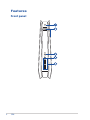
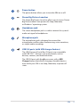
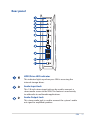
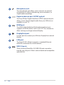
REPUBLIC OF
GAMERS
GR6
User Guide
E10138
First Edition
January 2015
COPYRIGHT INFORMATION
No part of this manual, including the products and software described in it, may be
reproduced, transmitted, transcribed, stored in a retrieval system, or translated into any
language in any form or by any means, except documentation kept by the purchaser for
backup purposes, without the express written permission of ASUSTeK COMPUTER INC.
(“ASUS”).
ASUS PROVIDES THIS MANUAL “AS IS” WITHOUT WARRANTY OF ANY KIND, EITHER EXPRESS
OR IMPLIED, INCLUDING BUT NOT LIMITED TO THE IMPLIED WARRANTIES OR CONDITIONS
OF MERCHANTABILITY OR FITNESS FOR A PARTICULAR PURPOSE. IN NO EVENT SHALL ASUS,
ITS DIRECTORS, OFFICERS, EMPLOYEES OR AGENTS BE LIABLE FOR ANY INDIRECT, SPECIAL,
INCIDENTAL, OR CONSEQUENTIAL DAMAGES (INCLUDING DAMAGES FOR LOSS OF PROFITS,
LOSS OF BUSINESS, LOSS OF USE OR DATA, INTERRUPTION OF BUSINESS AND THE LIKE), EVEN
IF ASUS HAS BEEN ADVISED OF THE POSSIBILITY OF SUCH DAMAGES ARISING FROM ANY
DEFECT OR ERROR IN THIS MANUAL OR PRODUCT.
Products and corporate names appearing in this manual may or may not be registered
trademarks or copyrights of their respective companies, and are used only for identification or
explanation and to the owners’ benefit, without intent to infringe.
SPECIFICATIONS AND INFORMATION CONTAINED IN THIS MANUAL ARE FURNISHED FOR
INFORMATIONAL USE ONLY, AND ARE SUBJECT TO CHANGE AT ANY TIME WITHOUT NOTICE,
AND SHOULD NOT BE CONSTRUED AS A COMMITMENT BY ASUS. ASUS ASSUMES NO
RESPONSIBILITY OR LIABILITY FOR ANY ERRORS OR INACCURACIES THAT MAY APPEAR IN THIS
MANUAL, INCLUDING THE PRODUCTS AND SOFTWARE DESCRIBED IN IT.
Copyright © 2015 ASUSTeK COMPUTER INC. All Rights Reserved.
LIMITATION OF LIABILITY
Circumstances may arise where because of a default on ASUS’ part or other liability, you
are entitled to recover damages from ASUS. In each such instance, regardless of the basis
on which you are entitled to claim damages from ASUS, ASUS is liable for no more than
damages for bodily injury (including death) and damage to real property and tangible
personal property; or any other actual and direct damages resulted from omission or failure of
performing legal duties under this Warranty Statement, up to the listed contract price of each
product.
ASUS will only be responsible for or indemnify you for loss, damages or claims based in
contract, tort or infringement under this Warranty Statement.
This limit also applies to ASUS’ suppliers and its reseller. It is the maximum for which ASUS, its
suppliers, and your reseller are collectively responsible.
UNDER NO CIRCUMSTANCES IS ASUS LIABLE FOR ANY OF THE FOLLOWING: (1) THIRDPARTY CLAIMS AGAINST YOU FOR DAMAGES; (2) LOSS OF, OR DAMAGE TO, YOUR RECORDS
OR DATA; OR (3) SPECIAL, INCIDENTAL, OR INDIRECT DAMAGES OR FOR ANY ECONOMIC
CONSEQUENTIAL DAMAGES (INCLUDING LOST PROFITS OR SAVINGS), EVEN IF ASUS, ITS
SUPPLIERS OR YOUR RESELLER IS INFORMED OF THEIR POSSIBILITY.
SERVICE AND SUPPORT
Visit our multi-language web site at http://support.asus.com
Contents
About this manual.............................................................................................. 5
Conventions used in this manual................................................................ 5
Typography.......................................................................................................... 5
Package contents................................................................................................ 6
Getting to know your GR6
Features.................................................................................................................. 8
Front panel........................................................................................................... 8
Bottom view......................................................................................................10
Top view.............................................................................................................10
Rear panel..........................................................................................................11
Using your GR6
Getting started...................................................................................................16
Positioning your GR6......................................................................................16
Connecting the AC power adapter...........................................................17
Connecting a display panel.........................................................................19
Connecting the keyboard or mouse.........................................................20
Turning on your GR6......................................................................................21
Using the Steam Big Picture Launcher......................................................22
Recovering your system.................................................................................23
Resetting your PC............................................................................................23
Removing everything and reinstalling Windows®..............................25
Turning off your GR6........................................................................................26
Putting your GR6 to sleep..............................................................................26
Entering the BIOS Setup.................................................................................26
Quickly enter the BIOS...................................................................................27
GR6
3
Contents
Upgrading your GR6
Upgrading memory modules.......................................................................30
Installing a 2.5-inch storage drive...............................................................35
Appendix
Safety information............................................................................................42
Setting up your system.................................................................................42
Care during use................................................................................................43
Regulatory notices............................................................................................44
ASUS contact information.............................................................................50
4
GR6
About this manual
This manual provides information about the hardware and software
features of your PC, organized through the following chapters:
Chapter 1: Getting to know your GR6
This chapter details the hardware components of your GR6.
Chapter 2: Using your GR6
This chapter provides you with information on using your GR6.
Chapter 3: Upgrading your GR6
This chapter provides information on how to upgrade the
memory modules and the storage drive of your GR6.
Appendices
This section includes notices and safety statements of your GR6.
Conventions used in this manual
To highlight key information in this manual, some texts are
presented as follows:
IMPORTANT! This message contains vital information that must be
followed to complete a task.
NOTE: This message contains additional information and tips that
can help complete tasks.
WARNING! This message contains important information that must
be followed to keep you safe while performing certain tasks and
prevent damage to your GR6's data and components.
Typography
Bold text
Indicates a menu or an item to select.
Italic
This indicates sections that you can
refer to in this manual.
GR6
5
Package contents
Your GR6 package contains the following items:
Technical documentations
GR6
AC power adapter*
set of screws
Power cable*
NOTE: * Actual product specifications and package contents may
vary depending on your country or region.
IMPORTANT! Bring the warranty card to the ASUS Service Center
for replacement of the defective components if the device or its
components fail or malfunction during normal and proper use within
the warranty period.
6
GR6
Getting to know your GR6
1
Features
Front panel
8
GR6
Power button
The power button allows you to turn the GR6 on or off.
Steam Big Picture Launcher
The Steam Big Picture Launcher allows you to access Steam
Big Picture mode from power off, sleep, hibernate,
or Windows® operating system.
Headphone jack
The stereo headphone jack is used to connect the system’s
audio out signal to headphones.
Microphone jack
The microphone jack is designed to connect the
microphone used for video conferencing, voice narrations,
or simple audio recordings.
USB 2.0 ports (with USB charger feature)
The USB (Universal Serial Bus) 2.0 ports are compatible
with USB 2.0/1.1 devices such as keyboards, mouse
devices, cameras, and hard disk drives.
The USB 2.0 port with the icon comes with a USB
Charger feature that allows charging of mobile devices
even while your GR6 is on sleep, hibernate, or power off
state.
GR6
9
Bottom view
Top view
Air vents
The air vents allow cool air to enter your GR6 chassis and
expel hot air out.
IMPORTANT! For optimum heat dissipation and air
ventilation, ensure that the air vents are free from
obstructions.
Rubber feet
The rubber feet help prevent the GR6 from slipping thus
providing more stability when the GR6 is in a stand-up
position.
10
GR6
Rear panel
HDD/Drive LED indicator
This indicator lights up when your GR6 is accessing the
internal storage drives.
Audio Input Jack
This 1/8-inch stereo input jack can be used to connect a
stereo audio source to the GR6. This feature is used mainly
to add audio to multimedia applications.
Audio Output Jack
This stereo audio jack is used to connect the system’s audio
out signal to amplified speakers.
GR6
11
Microphone jack
The microphone jack allows you to connect an external
microphone for video conferencing, voice narrations, or
simple audio recordings.
Digital audio out port (S/PDIF optical)
The Sony/Philips Digital Interface (S/PDIF) optical out port
allows you to transfer digital audio from your GR6 into an
amplifier or your TV.
HDMI port
The HDMI (High Definition Multimedia Interface) port
supports a Full-HD device such as an LCD TV or monitor to
allow viewing on a larger external display.
DisplayPort port
Use this port to connect your GR6 to a DisplayPort external
display.
LAN port
The 8-pin RJ-45 LAN port supports a standard Ethernet
cable for connection to a local network.
USB 3.0 ports
These Universal Serial Bus 3.0 (USB 3.0) ports provide a
transfer rate of up to 5 Gbit/s and are backward compatible
with USB 2.0.
12
GR6
Power input (DC 19V)
The supplied power adapter converts AC power to DC
power for use with this jack. Power supplied through this
jack supplies power to the PC. To prevent damage to the PC,
always use the bundled power adapter.
WARNING! The power adapter may become warm to
hot when in use. Do not cover the adapter and keep it
away from your body.
Cover lock latch + Kensington security slot
The cover lock latch fastens the side cover on your GR6.
The Kensington security slot allows you to secure your GR6
using Kensington® security products.
GR6
13
Using your GR6
2
Getting started
Positioning your GR6
The GR6 can be positioned standing up or lying down. When
positioning your GR6, ensure that the rubber studs or the rubber
feet are in contact with the flat and stable surface of your table or
desk.
Standing up
Lying down
Location of rubber studs
rubber feet
16
GR6
Connecting the AC power adapter
To connect the AC power adapter to your GR6:
A. Connect the AC power cord to the AC/DC adapter.
B. Plug the AC power cord into a 100V~240V power source.
C. Connect the DC power connector into your GR6’s power (DC)
input port.
NOTE: The power adapter may vary in appearance, depending on
your region.
GR6
17
IMPORTANT!
• We strongly recommend that you use only the AC power
adapter and cable that came with your GR6.
• Use a grounded wall socket while using your GR6.
• The socket outlet must be easily accessible and near your
GR6.
• To disconnect your GR6 from its main power supply, unplug
your GR6 from the power socket.
18
GR6
Connecting a display panel
You can connect a display panel or projector to your GR6 that has
the following connectors:
•
HDMI connector
•
DisplayPort connector
To connect a display panel to your GR6:
Connect a display cable either to the HDMI or DisplayPort port.
Connecting display via HDMI port
Connecting display via DisplayPort port
GR6
19
Connecting the keyboard or mouse
You can connect generally any USB keyboard and mouse to your
GR6. You can also connect a USB dongle for a wireless keyboard and
mouse set.
To connect a keyboard and mouse to your GR6:
Connect the USB cable from your keyboard and mouse to any of the
USB 2.0/3.0 ports of your GR6.
Connecting a USB keyboard or mouse
20
GR6
Turning on your GR6
Press the power button to turn on your GR6.
GR6
21
Using the Steam Big Picture
Launcher
The GR6 allows you to access Steam Big Picture mode from power
off, sleep, hibernate, or Windows® operating system.
Access Steam Big Picture Mode
In the following states, press the Steam Big Picture Launcher
to access Steam Big Picture mode:
•
Power off state
•
Sleep state
•
Hibernate state
•
Windows® operating system
NOTE: While using the Steam Big Picture Launcher, the Steam
software may automatically update to ensure the best user
experience. Once the update is complete, this function will return to
normal.
NOTE: For models without bundled operating system, please install
the Steam utility from the support DVD to enjoy the function of
Steam Big Picture Launcher.
22
GR6
Recovering your system
IMPORTANT! This section only applies for models with the bundled
operating system installed in your GR6.
Resetting your PC
The Reset your PC option restores your GR6 to its factory default
settings.
IMPORTANT! Back up all your data before using this option.
To reset your PC:
1. Press <F9> during bootup.
IMPORTANT! To go through POST, follow any of the ways described
in the Quickly enter the BIOS section.
2. From the screen, click Troubleshoot.
3.Select Reset your PC.
4.Click Next.
5.Select Only the drive where the Windows® is installed.
6.Select Just remove my files.
7.Click Reset.
GR6
23
Creating a USB recovery drive
You can create a USB recovery drive and use this to recover your PC’s
settings.
WARNING! All files on your USB storage device will be permanently
deleted during the process. Before you proceed, ensure that you back
up all your important data.
To create a USB recovery drive:
1. Launch the Control Panel from the All Apps screen.
2. From the Control Panel’s System and Security, click Action
Center.
3.Click Recovery > Create a recovery drive.
4.Click Next.
5. Select the USB storage device where you want to copy the recovery
files.
6.Click Next.
7.Click Create. Wait for the process to complete.
8. When done, click Finish.
24
GR6
Removing everything and reinstalling Windows®
IMPORTANT! This section only applies for models with the bundled
operating system installed in your GR6.
Restoring your GR6 to its original factory settings can be done using
the Remove everything and reinstall option in PC Settings. Refer
to the steps below to use this option.
IMPORTANT! Back up all your data before using this option.
NOTE: This process may take a while to complete.
1. Launch the Charms bar.
2.Click Settings > Change PC Settings > Update and recovery
> Recovery.
3. From the options on the Remove everything and reinstall
Windows®, click Get Started.
4. Follow the onscreen instructions to complete the re-installation
and reset process.
GR6
25
Turning off your GR6
Click Shutdown in Windows® operating system or press the Power
button to shut down your GR6. If your GR6 is unresponsive, press
and hold the power button for at least four seconds until your GR6
turns off.
Putting your GR6 to sleep
Click sleep in Windows® operating system to let your GR6 enter sleep
state.
Entering the BIOS Setup
BIOS (Basic Input and Output System) stores system hardware
settings that are needed for system startup in the GR6.
In normal circumstances, the default BIOS settings apply to most
conditions to ensure optimal performance. Do not change the
default BIOS settings except in the following circumstances:
• An error message appears on the screen during the system
bootup and requests you to run the BIOS Setup.
• You have installed a new system component that requires further
BIOS settings or update.
WARNING! Inappropriate BIOS settings may result to instability
or boot failure. We strongly recommend that you change the BIOS
settings only with the help of a trained service personnel.
26
GR6
Quickly enter the BIOS
• Turn off your GR6, press the power button to turn your GR6 back
on, and then press <F2> or <Del> during POST.
• When your GR6 is off, press the power button to turn on your
GR6. Press <F2> or <Del> during POST.
NOTE: POST (Power-On Self Test) is a series of software controlled
diagnostic tests that run when you turn on your PC.
GR6
27
28
GR6
Upgrading your GR6
3
Upgrading memory modules
Your GR6 comes with two SO-DIMM memory slots that allow you to
install up to two 8 GB DDR3L 204-pin SO-DIMMs for a maximum of
16 GB memory.
IMPORTANT! You can only install DDR3L (1.35V Low Voltage) 204-pin
SO-DIMM to the GR6’s DIMM slots.
NOTE: Refer to http://www.asus.com for the list of compatible
DIMMs.
To install or upgrade the memory modules:
1. Turn off your GR6.
2. Disconnect all cables and peripherals.
3. Place the GR6 on its side on a stable and flat surface.
4. Move down the latch at the rear panel to unlock the side cover.
NOTE: Before you remove the side cover, ensure that the UNLOCK
label on the latch is visible.
30
GR6
5. Slide the side cover towards the rear to detach it from the
chassis and then gently lift to remove it from the chassis.
6. Pry open the SO-DIMM slot cover.
GR6
31
7. Remove the memory modules.
To remove a memory module:
A. Press the retaining clips on each side to release the memory
module.
B. Carefully remove the memory module.
C. Repeat steps A and B to remove the other memory module.
NOTES:
• Use the same model and speed when replacing memory
modules.
• Remove the upper memory module first if you wish to
replace the lower memory module.
32
GR6
8. Get the replacement memory modules.
9. Install the new memory modules into the slot.
IMPORTANT! Always install on the lower slot first when installing one
or two modules.
To install a new memory module:
Align and insert the memory module into the slot (A) and then
press it down (B) until it is securely seated in place.
10. Replace the SO-DIMM slot cover. Ensure that it is fitted firmly
back into its place.
GR6
33
11. Replace the side cover and then slide it towards the front of GR6
to re-attach.
12. Press the latch upward to securely fasten the side cover to the
chassis.
34
GR6
Installing a 2.5-inch storage drive
The GR6 supports one 2.5-inch HDD or one 2.5-inch SSD for
additional storage capacity.
To install a 2.5-inch HDD or SSD:
1. Turn off your GR6.
2. Disconnect all cables and peripherals.
3. Place the GR6 on its side on a stable and flat surface.
4. Press down the latch at the rear panel to unlock the side cover.
NOTE: Before you remove the side cover, ensure that the UNLOCK
label on the latch is visible.
GR6
35
5. Slide the side cover towards the rear to detach it from the
chassis and then gently lift to remove it from the chassis.
6. Remove the four screws that secure the 2.5-inch HDD/SSD
extension bay.
7. Using the flap, pull the extension bay to remove it from the
chassis.
flap
36
GR6
8. Prepare the 2.5-inch HDD/SSD and the bundled set of four
screws.
9. Turn the extension bay upside down and place the 2.5-inch
HDD/SSD into the extension bay as shown. Ensure that screw
holes on the 2.5-inch HDD/SSD match the screw holes on the
extension bay.
2.5-inch HDD/SSD
HDD/SSD screw holes
2.5-inch extension bay
extension bay screw holes
10. Secure the 2.5-inch HDD/SSD to the extension bay with the
bundled set of screws.
GR6
37
11. Carefully place the 2.5-inch HDD/SSD and extension bay
assembly into the drive bay and then slide it towards the SATA
connector.
2.5-inch HDD/SSD and extension bay assembly
HDD/SSD SATA connector
Drive bay SATA connector
12. Secure the 2.5-inch extension bay with four screws.
38
GR6
13. Replace the side cover and then slide it towards the front of GR6
to re-attach.
14. Move the latch upward to securely fasten the side cover to the
chassis.
GR6
39
40
GR6
Appendix
Safety information
Your GR6 is designed and tested to meet the latest standards of
safety for information technology equipment. However, to ensure
your safety, it is important that you read the following safety
instructions.
Setting up your system
• Read and follow all instructions in the documentation before you
operate your system.
• Do not use this product near water or a heated source.
• Set up the system on a stable surface.
• Openings on the chassis are for ventilation. Do not block or cover
these openings. Make sure you leave plenty of space around the
system for ventilation. Never insert objects of any kind into the
ventilation openings.
• Use this product in environments with ambient temperatures
between 0˚C and 35˚C.
• If you use an extension cord, make sure that the total ampere
rating of the devices plugged into the extension cord does not
exceed its ampere rating.
42
GR6
Care during use
• Do not walk on the power cord or allow anything to rest on it.
• Do not spill water or any other liquids on your system.
• When the system is turned off, a small amount of electrical
current still flows. Always unplug the power cord from the power
outlets before cleaning the system.
• If you encounter the following technical problems with the
product, unplug the power cord and contact a qualified service
technician or your retailer.
– The power cord or plug is damaged.
– Liquid has been spilled into the system.
– The system does not function properly even if you follow
the operating instructions.
– The system was dropped or the cabinet is damaged.
– The system performance changes.
Lithium-Ion Battery Warning
CAUTION: Danger of explosion if battery is incorrectly
replaced. Replace only with the same or equivalent type
recommended by the manufacturer. Dispose of used batteries
according to the manufacturer’s instructions.
NO DISASSEMBLY
The warranty does not apply to the products that
have been disassembled by users
DO NOT throw the GR6 in municipal waste. This product has
been designed to enable proper reuse of parts and recycling. This
symbol of the crossed out wheeled bin indicates that the product
(electrical, electronic equipment, and mercury-containing button
cell battery) should not be placed in municipal waste. Check local
technical support services for product recycling.
GR6
43
Regulatory notices
REACH
Complying with the REACH (Registration, Evaluation, Authorization,
and Restriction of Chemicals) regulatory framework, we publish
the chemical substances in our products at ASUS REACH website at
http://csr.asus.com/english/REACH.htm
ASUS Recycling/Takeback Services
ASUS recycling and takeback programs come from our commitment
to the highest standards for protecting our environment. We believe
in providing solutions for you to be able to responsibly recycle our
products, batteries, other components, as well as the packaging
materials. Please go to http://csr.asus.com/english/Takeback.htm
for the detailed recycling information in different regions.
COATING NOTICE
IMPORTANT! To provide electrical insulation and maintain electrical
safety, a coating is applied to insulate the device except on the areas
where the I/O ports are located.
Federal Communications Commission Statement
This device complies with Part 15 of the FCC Rules. Operation is
subject to the following two conditions:
• This device may not cause harmful interference, and
• This device must accept any interference received including
interference that may cause undesired operation.
This equipment has been tested and found to comply with the limits
for a Class B digital device, pursuant to Part 15 of the FCC Rules.
These limits are designed to provide reasonable protection against
harmful interference in a residential installation. This equipment
generates, uses and can radiate radio frequency energy and, if not
installed and used in accordance with manufacturer’s instructions,
may cause harmful interference to radio communications. However,
there is no guarantee that interference will not occur in a particular
installation. If this equipment does cause harmful interference to
44
GR6
radio or television reception, which can be determined by turning
the equipment off and on, the user is encouraged to try to correct
the interference by one or more of the following measures:
• Reorient or relocate the receiving antenna.
• Increase the separation between the equipment and receiver.
• Connect the equipment to an outlet on a circuit different from
that to which the receiver is connected.
• Consult the dealer or an experienced radio/TV technician for
help.
CAUTION: Any changes or modifications not expressly approved by
the grantee of this device could void the user’s authority to operate
the equipment.
RF exposure warning
This equipment must be installed and operated in accordance with
provided instructions and the antenna(s) used for this transmitter
must be installed to provide a separation distance of at least 20
cm from all persons and must not be co-located or operating in
conjunction with any other antenna or transmitter. End-users and
installers must be provide with antenna installation instructions
and transmitter operating conditions for satisfying RF exposure
compliance.
Declaration of Conformity (R&TTE directive 1999/5/EC)
The following items were completed and are considered relevant
and sufficient:
•
•
•
•
Essential requirements as in [Article 3]
Protection requirements for health and safety as in [Article 3.1a]
Testing for electric safety according to [EN 60950]
Protection requirements for electromagnetic compatibility in
[Article 3.1b]
• Testing for electromagnetic compatibility according to [EN 301
489-1] & [EN 301 489-17]
• Effective use of the radio spectrum as in [Article 3.2]
• Radio test suites according to [EN 300 328-2]
GR6
45
France Restricted Wireless Frequency Bands
Some areas of France have a restricted frequency band. The worst
case maximum authorized power indoors are:
• 10mW for the entire 2.4 GHz band (2400 MHz–2483.5 MHz)
• 100mW for frequencies between 2446.5 MHz and 2483.5 MHz
NOTE: Channels 10 through 13 inclusive operate in the band 2446.6
MHz to 2483.5 MHz.
There are few possibilities for outdoor use: On private property or on
the private property of public persons, use is subject to a preliminary
authorization procedure by the Ministry of Defense, with maximum
authorized power of 100mW in the 2446.5–2483.5 MHz band. Use
outdoors on public property is not permitted.
In the departments listed below, for the entire 2.4 GHz band:
• Maximum authorized power indoors is 100mW
• Maximum authorized power outdoors is 10mW
Departments in which the use of the 2400–2483.5 MHz band is
permitted with an EIRP of less than 100mW indoors and less than
10mW outdoors:
46
01
Ain
02
Aisne
03
Allier
05
Hautes Alpes
08
Ardennes
09
Ariège
11
Aude
12
Aveyron
16
Charente
24
Dordogne
25
Doubs
26
Drôme
32
Gers
36
Indre
37
Indre et Loire
41
Loir et Cher
45
Loiret
50
Manche
55
Meuse
58
Nièvre
59
Nord
60
Oise
61
Orne
63
Puy du Dôme
64
Pyrénées Atlantique
66
Pyrénées
Orientales
67
Bas Rhin
70
Haute Saône
71
Saône et Loire 75
Paris
82
Tarn et Garonne
84
Vaucluse
88
Vosges
89
Yonne
90
Territoire de
Belfort
94
Val de Marne
GR6
This requirement is likely to change over time, allowing you to use
your wireless LAN card in more areas within France. Please check
with ART for the latest information (www.art-telecom.fr)
NOTE: Your WLAN Card transmits less than 100mW, but more than
10mW.
Canadian Department of Communications Statement
This digital apparatus does not exceed the Class B limits for
radio noise emissions from digital apparatus set out in the
Radio Interference Regulations of the Canadian Department of
Communications.
This class B digital apparatus complies with Canadian ICES-003.
IC Radiation Exposure Statement for Canada
This equipment complies with IC radiation exposure limits set forth
for an uncontrolled environment. To maintain compliance with IC
RF exposure compliance requirements, please avoid direct contact
to the transmitting antenna during transmitting. End users must
follow the specific operating instructions for satisfying RF exposure
compliance.
Operation is subject to the following two conditions:
• This device may not cause interference and
• This device must accept any interference, including interference
that may cause undesired operation of the device.
GR6
47
CE Mark Warning
CE marking for devices without wireless LAN/Bluetooth
The shipped version of this device complies with the requirements
of the EEC directives 2004/108/EC “Electromagnetic compatibility”
and 2006/95/EC “Low voltage directive”.
CE marking for devices with wireless LAN/ Bluetooth
This equipment complies with the requirements of Directive 1999/5/
EC of the European Parliament and Commission from 9 March, 1999
governing Radio and Telecommunications Equipment and mutual
recognition of conformity.
Wireless Operation Channel for Different Domains
48
N. America
2.412-2.462 GHz
Ch01 through CH11
Japan
2.412-2.484 GHz
Ch01 through Ch14
Europe ETSI
2.412-2.472 GHz
Ch01 through Ch13
GR6
ENERGY STAR complied product
ENERGY STAR is a joint program of the U.S.
Environmental Protection Agency and the U.S.
Department of Energy helping us all save money
and protect the environment through energy
efficient products and practices.
All ASUS products with the ENERGY STAR logo
comply with the ENERGY STAR standard, and the
power management feature is enabled by default. The monitor and
computer are automatically set to sleep after 10 and 30 minutes of
user inactivity. To wake your computer, click the mouse or press any
key on the keyboard.
Please visit http://www.energy.gov/powermanagement for
detail information on power management and its benefits to the
environment. In addition, please visit http://www.energystar.gov for
detail information on the ENERGY STAR joint program.
NOTE: Energy Star is NOT supported on FreeDOS and Linux-based
products.
GR6
49
ASUS contact information
ASUSTeK COMPUTER INC.
Address
15 Li-Te Road, Peitou, Taipei, Taiwan 11259
Telephone +886-2-2894-3447
Fax +886-2-2890-7798
E-mail
[email protected]
Web site
www.asus.com.com/
Technical Support
Telephone Fax
Online support
+86-21-38429911
+86-21-5866-8722, ext. 9101#
http://www.asus.com/tw/support/
ASUS COMPUTER INTERNATIONAL (America)
Address
800 Corporate Way, Fremont, CA 94539, USA
Telephone+1-510-739-3777
Fax +1-510-608-4555
Web site
http://www.asus.com/us/
Technical Support
Support fax
Telephone Online support
+1-812-284-0883
+1-812-282-2787
http://www.service.asus.com/
ASUS COMPUTER GmbH (Germany and Austria)
Address
Fax
Web site
Online contact
Harkort Str. 21-23, D-40880 Ratingen, Germany
+49-2102-959911
http://www.asus.com/de
http://eu-rma.asus.com/sales
Technical Support
Telephone+49-1805-010923*
Support Fax
+49-2102-9599-11
Online support
http://www.asus.com/de/support/
Manufacturer
ASUSTeK Computer Inc.
Tel:
+886-2-2894-3447
Address:
No. 150, LI-TE RD., PEITOU, TAIPEI 112,
TAIWAN
Authorised
ASUSTeK Computer GmbH
representative in Address: HARKORT STR. 21-23, 40880 RATINGEN,
Europe
GERMANY
50
GR6
EC Declaration of Conformity
We, the undersigned,
Manufacturer:
ASUSTeK COMPUTER INC.
Address:
4F, No. 150, LI-TE Rd., PEITOU, TAIPEI 112, TAIWAN
Authorized representative in Europe:
ASUS COMPUTER GmbH
Address, City:
HARKORT STR. 21-23, 40880 RATINGEN
Country:
GERMANY
declare the following apparatus:
P ro d u c t n a m e :
D e s k to p P C
M o d eln am e :
G R 8,G R 6
conform with the essential requirements of the foll
owing directives:
2004/108/EC-EMC Directive
EN 55022:2010+AC:2011
EN 61000-3-2:2006+A2:2009
EN 55013:2001+A1:2003+A2:2006
EN 55024:2010
EN 61000-3-3:2013
EN 55020:2007+A11:2011
1999/5/EC-R&TTE Directive
EN 300 328 V1.8.1(2012-06)
EN 300 440-1 V1.6.1(2010-08)
EN 300 440-2 V1.4.1(2010-08)
EN 301 511 V9.0.2(2003-03)
EN 301 908-1 V5.2.1(2011-05)
EN 301 908-2 V5.2.1(2011-07)
EN 301 893 V1.7.1(2012-06)
EN 302 544-2 V1.1.1(2009-01)
EN 302 623 V1.1.1(2009-01)
EN 50360:2001
EN 62479:2010
EN 50385:2002
EN 50566:2013
EN 301 489-1 V1.9.2(2011-09)
EN 301 489-3 V1.4.1(2002-08)
EN 301 489-4 V1.4.1(2009-05)
EN 301 489-7 V1.3.1(2005-11)
EN 301 489-9 V1.4.1(2007-11)
EN 301 489-17 V2.2.1(2012-09)
EN 301 489-24 V1.5.1(2010-09)
EN 302 326-2 V1.2.2(2007-06)
EN 302 326-3 V1.3.1(2007-09)
EN 301 357-2 V1.4.1(2008-11)
EN 302 291-1 V1.1.1(2005-07)
EN 302 291-2 V1.1.1(2005-07)
2006/95/EC-LVD Directive
EN 60950-1 / A12:2011
EN 60065:2002 / A12:2011
2009/125/EC-ErP Directive
Regulation (EC) No. 1275/2008
Regulation (EC) No. 278/2009
Regulation (EC) No. 642/2009
Regulation (EC) No. 617/2013
2011/65/EU-RoHS Directive
Ver. 140331
CE marking
(EC conformity marking)
Position : CEO
Name :
Jerry
Original Declaration Date: 29/08/2014
Corrected Declaration Date: 09/03/2015
Year to begin affixing CE marking: 2015
Shen
Signature : __________
GR6
51
DECLARATION OF CONFORMITY
Per FCC Part 2 Section 2. 1077(a)
Responsible Party Name:
Asus Computer International
800 Corporate Way, Fremont, CA 94539.
Address:
Phone/Fax No:
(510)739-3777/(510)608-4555
hereby declares that the product
Product Name : Desktop PC
Model Number :GR8,GR6
Conforms to the following specifications:
FCC Part 15, Subpart B, Unintentional Radiators
Supplementary Information:
This device complies with part 15 of the FCC Rules. Operation is subject to the
following two conditions: (1) This device may not cause harmful interference,
and (2) this device must accept any interference received, including interference
that may cause undesired operation.
Representative Person's Name
:
Steve Chang / President
Signature :
Original Declaration Date :
Corrected Declaration Date :
Aug. 29, 2014
Mar. 09, 2015
Ver. 140331
52
GR6