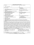
1
AccuRange™ High Speed Interface
ISA and PC-104 Formats
User’s Manual
Rev. 2.5
For use with AccuRange HSIF-ISA and PC104
September 5, 2003
Acuity
A division of Schmitt Measurement Systems, Inc.
2765 NW Nicolai St.
Portland, OR 97210
www.acuityresearch.com
ISA PC104 HSIF User’s Manual
Rev 9/03
i
Limited Warranty
Acuity, a division of Schmitt Measurement Systems, Inc., makes the following
limited warranties. These limited warranties extend to the original purchaser and
to no other purchaser or transferee.
Limited One Year Parts and Labor Warranty
Acuity warrants this product and its parts against defects in materials or
workmanship for a period of one year after the date of original retail purchase.
During this period, Acuity will, at its option, repair or replace a defective product
or part without charge to you.
Warranty Conditions
The above LIMITED WARRANTIES are subject to the following conditions:
1. Warranties extend only to products manufactured by Acuity.
2. Warranties extend only to defects in materials or workmanship as limited
above. Warranties extend only to defects which occur during normal use and do
not extend to damage to products or parts which results from alteration, repair,
modification, faulty installation or service by anyone other than an authorized
Acuity service center, damage to products or parts caused by accident, abuse,
misuse or maintenance, mishandling, misapplication, or damage caused by acts
of God.
3. You must retain your bill of sale or provide other proof of purchase.
4. Any replacement parts furnished at no cost to the purchaser in fulfillment of
this warranty are warranted only for the unexpired portion of the original
warranty.
ALL WARRANTIES REQUIRED TO BE IMPLIED BY STATE LAW
ARE EXPRESSLY LIMITED TO THE DURATION OF THE LIMITED
WARRANTIES SET FORTH ABOVE. Some states do not allow limitations
on how long an implied warranty lasts, so the above limitation may not apply to
you. WITH THE EXCEPTION OF ANY WARRANTIES REQUIRED TO
BE IMPLIED BY STATE LAW AS HEREBY LIMITED, THE
FOREGOING EXPRESS WARRANTY IS EXCLUSIVE AND IN LIEU OF
ALL OTHER WARRANTIES.
IN NO EVENT SHALL ACUITY BE LIABLE FOR SPECIAL,
INCIDENTAL, CONSEQUENTIAL OR PUNITIVE DAMAGES,
INCLUDING, WITHOUT LIMITATION, INJURY OR DAMAGE TO
PERSONS OR OTHER PROPERTY, INCONVENIENCE, LOSS OF
GOODWILL, LOST PROFITS OR REVENUE, LOSS OF USE OF THIS
PRODUCT OR ANY ASSOCIATED EQUIPMENT, COST OF
SUBSTITUTIVE EQUIPMENT DOWNTIME COSTS OR CLAIMS OF
ANY PARTY DEALING WITH PURCHASER FOR SUCH DAMAGES,
RESULTING FROM THE USE OF THIS PRODUCT OR FROM
DEFECTS IN THIS PRODUCT, OR ARISING FROM BREACH OF
WARRANTY OR CONTRACT, NEGLIGENCE OR ANY OTHER
ISA PC104 HSIF User’s Manual
Rev 9/03
ii
LEGAL THEORY. Some states do not allow the exclusion or limitation of
incidental or consequential damages, so the above limitation may not apply to
you.
Procedures for Obtaining Warranty Service
1. Contact your Acuity distributor or call Acuity to obtain a return merchandise
authorization (RMA) number within the applicable warranty period. Acuity will
not accept any returned product without an RMA number.
2. Ship the product to Acuity, postage prepaid, together with your bill of sale or
other proof of purchase. your name, address, description of the problem(s). Print
the RMA number you have obtained on the outside of the package.
This device complies with part 15 of the FCC Rules. Operation is subject to
the following two conditions:
(1) This device may not cause harmful interference, and (2) this device must
accept any interference received, including interference that may cause
undesired operation.
Note: This equipment has been tested and found to comply with the limits for a
Class A digital device, pursuant to part 15 of the FCC rules. These limits are
designed to provide reasonable protection against harmful interference when the
equipment is operated in a commercial environment. This equipment generates,
uses, and can radiate radio frequency energy and, if not installed and used in
accordance with the instruction manual, may cause harmful interference to radio
communications. Operation of this device in a residential area is likely to cause
harmful interference in which case the user will be required to correct the
interference at their own expense.
Copyright 2003 Acuity, a division of Schmitt Measurement Systems, Inc.
ISA PC104 HSIF User’s Manual
Rev 9/03
iii
TABLE OF CONTENTS
1. ACCURANGE ISA AND PC104 HIGH SPEED INTERFACE
CARDS
1
1.1
General Description
1
1.2
Sensor Configuration and Sample Rate
2
1.3
Motor Power
2
1.4
II/O Connectors
1.4.1
9 Pin Power and Signal Connector P1
1.4.2
Power and Signal Connector Description
1.4.3
25 Pin I/O Connector P2
1.4.4
P2 Pin Descriptions
3
3
3
4
4
1.5
II/O Port Interface
1.5.1
Port Descriptions
7
8
1.6
Sampled Data Format
1.6.1
Description of Sampled Data Format
9
10
1.7
Interrupt Driven Operation
11
1.8
Interface Resolution and Sample Rates
12
1.9
Interface Installation and Checkout
1.9.1
Diagnostics
12
13
1.10
13
High Speed Interface Data Sheet
ISA PC104 HSIF User’s Manual
Rev 9/03
1
1. AccuRange ISA and PC104 High Speed Interface
Cards
1.1
General Description
The AccuRange High Speed Interface is an interface board that takes samples
from the AccuRange 4000 optical rangefinder. Two models are available. One
model plugs into an IBM-PC or compatible ISA or EISA bus. The other model is
PC/104 compatible. Samples come over the bus in an 8 byte format that includes
a 19 bit range value and 1 byte values for signal strength, ambient light, and
sensor internal temperature as well as status and general purpose input bits.
These ni puts, along with external enable/disable control of sampling, allow
precise synchronization with external events.
The ISA/EISA board has an IBM PC form factor, and will fit in a half-length PC
ISA slot. The PC/104 board conforms to the PC/104 specification for a 16-bit
stackthrough module. Data is transferred over an 8 bit I/O port, with the address
selected with on-board jumpers.
The interface board operates by measuring the range-dependent pulse width
output of the AccuRange 4000. To use the 4000 with the High Speed Interface,
the Current Loop option must not be installed in the sensor. Each pulse on the
pulse width output is timed on the Interface board by a timer with a clock rate of
80 MHz. The sample rate of the interface is therefore controlled by the sample
rate for which the 4000 is configured. Since the pulse width output can be set to
repeat at up to 50 KHz, that is the maximum sample rate of the interface.
The data collected by the high speed interface is not scaled or calibrated in any
way. It can be used to create calibrated distance output using software modules
and tables supplied with the interface or though user-written algorithms. The data
can be used to calculate distance as each sample is collected, although the more
typical application will collect a batch of samples and create distance readings
from the entire group after high-speed collection is finished.
Other features of the interface include memory buffer empty, half full, and
overflow status indicators, external sample start/stop control, and three general
purpose input bits that allow synchronous recording of events while sampling.
The board can also be ordered with power control circuitry for two small motors.
This is not full servo control, but it allows motor power to be programmed. If the
motors have encoders, the encoders may be sampled with the sensor data to
provide position information in the sample stream in scanning systems. Each
motor can be driven with up to 2 amps at 12 to 48 volts. Power for the motors
must be supplied to the board, where it is pulse-width modulated (ISA/EISA
model only) or DC level controlled (depending on the configuration ordered)
according to the programmed power level.
ISA PC104 HSIF User’s Manual
Rev 9/03
1
1.2
Sensor Configuration and Sample Rate
When using the High Speed Interface, all configuration of the 4000 is done via
the serial port, or push-button interface, just as it would be when using the sensor
without the High Speed Interface. The communication path from the 4000 to the
High Speed Interface is a one-way data path only; the sensor cannot be
configured through the Interface. Since the sample rate of the Interface is
controlled by the rate of the pulse width output of the 4000, using the Set Sample
Interval command over the serial port will set the sample rate for the Interface,
with one limitation. The lowest rate at which the internal sampling and therefore
the pulse width output of the sensor can operate is 31 samples per second (32
milliseconds per sample). Setting lower sample rates will not reduce the pulse
width output frequency or the sample rate of the Interface.
To obtain the slowest possible sample rate from the High Speed Interface and the
maximum resolution per sample, use the serial interface to configure the 4000 for
a maximum expected range of 9950 inches, and then set the sample rate. Setting
the maximum range to shorter distances (including the default setting) may cause
the pulse width to repeat at higher frequencies than the sample rate set,
depending on the maximum expected range and sample rate specified. For short
maximum range settings, the pulse frequency will be about 5 Khz for sample
rates below that.
The maximum sample
microseconds/sample).
1.3
rate
is
50,000
samples
per
second
(20
Motor Power
The AccuRange High Speed Interface can be ordered with two motor power
control and encoder reading channels. Each motor may be set to one of 64
software controlled power levels via commands to the board. If the motors have
encoders which are connected to the encoder inputs, two 8-bit values from the
encoders are decoded and inserted into the data stream, giving the position of
each motor, modulo 256. If the encoders provide index pulses, these can be
applied to two of the general purpose input lines and used to determine the
absolute positions of the motors. See the description of the 25 pin I/O connector
for encoder connection details.
If motors are to be driven by the power amplifier on the board, the motors and
motor power must be connected to P2. Motor 1 should be connected between
pins 14 and 16, and motor 2 between pins 1 and 2. A separate power supply is
required to drive the motors. Connect the motor power supply to pin 3 and the
power supply ground to pin 15.
The ISA/EISA model Motor control can be ordered in either of 2 configurations.
The first is pulse-width modulation and is suitable for driving D.C. brush motors
ISA PC104 HSIF User’s Manual
Rev 9/03
2
at up to 2 amps at 48 volts. The other configuration is variable voltage control,
and is suitable for small motors and brushless D.C. motors with embedded
electronics and steady-state power levels up to 5 watts (36 Volts max) per motor.
Pulse width modulation tends to be more power efficient, while variable voltage
control is suitable for smaller motors or brushless motors.
With pulse-width control, motor direction can be reversed by switching the motor
connections, or through software control of the motor power. There is no
software direction control with variable voltage control.
The PC/104 model is available in only the variable voltage control configuration.
1.4
II/O Connectors
There are 2 connectors on the High Speed Interface. The 9 pin connector supplies
power and receives signals from the AccuRange 4000. The 25 pin connector is
used for powering the motors and reading the motor encoders, general purpose
inputs, and sample control input.
1.4.1
9 Pin Power and Signal Connector P1
Pin
1
2
3
4
5
6
7
8
4000 Wire
Red
Black
Orange
Brown
Yellow
Blue
Green
Purple
Function
Power, +5V (5-6V)
Ground
Heater Power, +5V (4.5-7V)
Heater Power Return
Temperature, 0-5 V
Pulse Width Range Signal
Ambient light signal, 0-5 V
Amplitude signal, 0-5 V
Direction
Out
Out
In
In
In
In
P1: Power and Signal Connector Wiring
1.4.2
Power and Signal Connector Description
The line descriptions for P1 are the same as the descriptions of the power and
signal lines in the AccuRange 4000 Power and Signal Cable Wire Description
section. Pins 1-4 supply sensor power and sensor heater power and ground lines.
The remaining lines are inputs for the signals from the AccuRange 4000. Pins 5,
7, and 8 are the inputs for the analog signals, with 2K impedance. Pin 6 is the
input for the pulse width range signal.
ISA PC104 HSIF User’s Manual
Rev 9/03
3
1.4.3
25 Pin I/O Connector P2
P2 includes general purpose input lines, a sample start/stop control line,
quadrature encoder input lines, and power for encoders or other applications.
Pin
Top Row
Function
1
Motor 2 Control
Direction Pin
Direction
Out
2
Motor 2 Return
Out
3
Motor Power Supply
In
4
No Connection
5
+5V Power, 100 mA.
6
Ground
7
Ground
8
Ground
9
Ground
10
Ground
11
Bottom Row
Function
14
Motor 1 Control
Out
15
Motor Power Ground
16
Motor 1 Return
17
No Connection
18
+5V Power, 100 mA
19
Motor 2 Encoder Ch A In
20
Motor 2 Encoder Ch B In
21
Motor 1 Encoder Ch A In
22
Motor 1 Encoder Ch B In
23
No Connection
24
General Purpose Input 1/
Encoder 1 Index Pulse
In
25
General Purpose Input 3 In
Out
Out
Out
No Connection
12
Start/Stop Sample Ctrl
In
13
General Purpose Input 2/
Encoder 2 Index Pulse In
P2: I/O Connector
1.4.4
P2 Pin Descriptions
Pin 1: Motor 2 Control
If used, motor 2 should be connected between this pin and pin 2. If the pulse
width motor control option was ordered (ISA/EISA model only), this pin and pin
2 will drive motor 2 with a 20 KHz pulse width signal, as set through software
ISA PC104 HSIF User’s Manual
Rev 9/03
4
commands. If the variable voltage motor control option was ordered, the output
voltage level is varied as commanded.
Pin 2: Motor 2 Return.
If used, motor 2 should be connected between this pin and pin 1.
Pin 3: Motor Power.
The external power supply for the motors should be applied to this line, at +12 to
+48 Volts, depending on the motor used. The line may draw up to 2 amps.
Pin 4: No Connection.
Pin 5: +5V power output.
Primarily intended as power for the motor 1 encoder, but it may be used to drive
other hardware, up to 100 mA maximum.
Pins 6-10: Ground
May be used as ground for encoders or other hardware powered by +5V on pins
5 and 18.
Pin 11: No Connection.
Pin 12: Start/Stop Sample Control Input.
When high, this input enables sampling and samples will be taken until the onboard buffer is full. When pulled low, sampling will stop. Samples are always
completed, so that a full 8 byte sample is always buffered. This line is pulled up
with an on-board 10Kohm resistor, so sampling is enabled when the input is left
open. The first sample following resumption of sampling after stopping the
sampling will not contain valid data, and must be read and discarded.
Pin 13: General purpose input bit 2 / Motor 2 index pulse input.
This may be used to sample external signals. The value of the bit will is included
in the sampled data stream. This may be used to sample motor encoder index
pulses or other events in order to synchronize the sample data with the event. The
signal is latched so that any high signal of 500 nanoseconds or longer during a
sample interval will appear as a high level in at least one sample. If the input is
high across a sampling interval boundary, it will appear in 2 consecutive samples.
This is intended for use with encoder index pulses.
Pin 14: Motor 1 Control.
If used, motor 1 should be connected between this pin and pin 14. If the pulse
width motor control option was ordered (ISA/EISA model only), this pin and pin
14 will drive motor 1 with a 20 KHz pulse width signal, as set through software
ISA PC104 HSIF User’s Manual
Rev 9/03
5
commands. If the variable voltage motor control option was ordered, the output
voltage level is varied as commanded.
Pin 15: Motor Power Ground.
The external power supply ground for the motors should be connected to this pin.
Pin 16: Motor 1 Ground.
If used, motor 2 should be connected between this pin and pin 16.
Pin 17: No Connection.
Pin 18: +5V power.
Primarily intended as power for the motor 2 encoder, but it may be used to drive
other hardware, up to 100 milliamps maximum.
Pin 19: Motor 2 Encoder Channel A.
If the motor control option is installed on the board, this input is decoded with
pin 20 as a quadrature encoder signal from motor 2. The input should be a TTLlevel signal and may switch at up to 1.5 Mhz. The encoder positions are
converted to 8 bit position values that ate included in the data stream. Each
transition of pins 19 or 20 causes an up or down count in the position, so each
quadrature cycle is effectively multiplied by 4 for the best possible resolution.
Pin 20: Motor 2 Encoder Channel B.
If the motor control option is installed on the board, this input is decoded with
pin 19 as a quadrature encoder signal from motor 2. The input should be a TTLlevel signal and may switch at up to 1.5 Mhz.
Pin 21: Motor 1 Encoder Channel A.
If the motor control option is installed on the board, this input is decoded with
pin 22 as a quadrature encoder signal from motor 1. The input should be a TTLlevel signal and may switch at up to 1.5 Mhz. The encoder positions are
converted to 8 bit position values that are included in the data stream. Each
transition of pins 21 or 22 causes an up or down count in the position, so each
quadrature cycle is effectively multiplied by 4 for the best possible resolution.
Pin 22: Motor 1 Encoder Channel B.
If the motor control option is installed on the board, this input is decoded with
pin 21 as a quadrature encoder signal from motor 1. The input should be a TTLlevel signal and may switch at up to 1.5 Mhz.
Pin 23: No Connection.
Pin 24: General purpose input bit 1 / Motor 1 index pulse input.
ISA PC104 HSIF User’s Manual
Rev 9/03
6
This may be used to sample external signals. The value of the bit will is included
in the sampled data stream. This may be used to sample motor encoder index
pulses or other events in order to synchronize the sample data with the event. The
signal is latched high so that any high signal of 500 nanoseconds or longer during
a sample interval will appear as a high level in at least one sample. If the input is
high across a sampling interval boundary, it will appear in 2 consecutive samples.
This is intended for use with encoder index pulses.
Pin 25: General purpose input bit 3.
This may be used to sample external signals. The value of the bit will be
inverted and inserted into the sample data stream. This may be used to sample
events in order to synchronize the sample data with the event. Note: the bit is
INVERTED and NOT LATCHED, so if the event does not last for at least one
sample interval it may be missed.
1.5
II/O Port Interface
The High Speed Interface is accessed as a set of I/O ports on the ISA or PC/104
bus. The board occupies a group of 8 contiguous port address locations starting at
the address determined by the port address jumper J1.
Jumpers
ISA/EISA Model:
PC/104 Model:
Address
J1-4
J1-3
J1-2
J1-1
JMP -4 JMP -3 JMP -2 JMP -1
off
off
off
off
off
off
off
off
on
on
on
on
on
on
on
on
off
off
off
off
on
on
on
on
off
off
off
off
on
on
on
on
off
off
on
on
off
off
on
on
off
off
on
on
off
off
on
on
off
on
off
on
off
on
off
on
off
on
off
on
off
on
off
on
000Hex
040Hex
080Hex
0C0Hex
100Hex
140Hex
180Hex
1C0Hex
200Hex Default
240Hex
280Hex
2C0Hex
300Hex
340Hex
380Hex
3C0Hex
Port Address Base Jumper Map
ISA PC104 HSIF User’s Manual
Rev 9/03
7
Within the 8 byte address space occupied by the board, locations 0-3 are used.
They are addressed as offsets from the base address selected by the jumpers. For
example, if address 280 Hex is selected as the base, the port addresses for the
board are 280H, 281H, 282H, and 283H.
Any one of 16 locations between 0 Hex and 3C0 Hex may be selected for the
port base. Choose a location from the table below that does not interfere with
other peripherals in your system.
Offset from Base Address Access
0
Function
Read-Write
Read: Sample Data
Write: Send Command
Read Only
Buffer Status
Write Only
Motor 1 Power and Direction
Write Only
Motor 2 Power and Direction
Repeat Functions of ports 0-3
1
2
3
4-7
I/O Port Address Map
1.5.1
Port Descriptions
Port 0 Data
Port 1 Data
Read: Sensor Data (see Sampled Data Format Section)
Write: Command value: 0 = Clear Buffer Full Flag
3 = Reset Board
Read: Buffer Status:
Bit 0 = 0: No data available
Bit 0 = 1: Data available
Bit 1 = 0: Buffer Less Than Half Full
Bit 1 = 1: Buffer At Least Half Full
Port 2 Data
Write: Bits 0-5: Motor 1 Power Level
Bit 7:
Motor 1 Direction
Port 3 Data
Write: Bits 0-5: Motor 2 Power Level
Bit 7:
Motor 2 Direction
I/O Port Data Definition
Port 0: The base address + 0 is a read/write port. When read, it gives the next
byte in the data stream. If the memory buffer is empty, this byte will be
meaningless. It is not possible to tell from the data content whether the byte is
valid data or not.
There are 2 possible ways to determine whether the data is good. Bit 0 of the
status port (offset 1) may be read and tested. A 1 indicates that the next byte read
from the data port will be valid data. The other method is to test bit 1 of the status
ISA PC104 HSIF User’s Manual
Rev 9/03
8
port. A 1 here indicates that the buffer is half full. A group of bytes half the size
of the buffer may then be read before there is any danger of the buffer being
empty.
Writing to port 0 sends a command to the board. The command code is contained
in the lower 2 bits of the byte written. The 2 commands are as follows:
Clear Buffer Overflow Flag: Writing a byte with bits 0 and 1 clear will clear
the buffer overflow flag in the data stream. See the Sampled Data Format section
for further description of this flag.
Board Reset: Writing a byte to port 0 with bits 0 and 1 set resets the interface
board. This clears the buffer overflow flag and empties the data buffer. The next
byte following a reset will be the first byte of an 8 byte sample. The first sample
following a Reset will not contain reliable data, so it should be read and
discarded. The Reset command also clears the encoder counters, resetting them
to 0.
Port 1: The base address + 1 is a read only port. Only the lower 2 bits have
meaning. If bit 0 is clear, there is no data available at port 0 for reading. Reading
port 0 should be avoided until port 1 bit 0 reads as 1, since the byte read may or
may not be a valid data byte: The next byte could arrive in the buffer between
reading the status byte and reading the data byte. Port 1 bit 1 is a half-full status
bit. If this bit is set, a stream of bytes equal to half the length of the buffer may be
read without checking the status port. Standard buffer sizes are 2K bytes and 16K
bytes.
Port 2: The base address + 2 is a write only port. The lower 6 bits of the byte
written are the power level for motor 1. A value of 0 is off, and 63 is full power.
Bit 6 is unused. The high bit (bit 7) is the direction, which is effective only with
the pulse width motor driver configuration (ISA/EISA model only). The direction
bit has no effect if the board is configured with variable voltage motor drivers.
Port 3: The base address + 3 is a write only port. The lower 6 bits of the byte
written are the power level for motor 2. A value of 0 is off, and 63 is full power.
Bit 6 is unused. The high bit (bit 7) is the direction, which is effective only with
the pulse width motor driver configuration (ISA/EISA model only). The direction
bit has no effect if the board is configured with variable voltage motor drivers.
1.6
Sampled Data Format
The interface board collects 8 bytes/sample in a sequential stream. Reading from
the port at offset 0 will read the next byte in the data stream, if it is available (See
I/O Interface section, above). When reading from the board, multiples of 8 bytes
should be read to ensure that a complete sample is obtained. If memory buffer
overflow occurs, the board will always drop complete samples, so that
synchronization is not lost. If a software board reset command is issued, the next
ISA PC104 HSIF User’s Manual
Rev 9/03
9
byte read will be the first byte of a complete sample, and unread and partially
read samples will be lost.
In general the values for amplitude and ambient light level, will correspond
closely to the values from the 4000’s serial interface, with the ASCII format
serial data being 4 times the High Speed Interface values for amplitude and
ambient light. However, the values will not match exactly, and the calibration
software supplied for use with the High Speed Interface must be used with the
values obtained from the High Speed Interface, not serial data. The temperature
and range have different scale factors from the serial data and must be scaled
using algorithms found in the software supplied with the interface.
Byte 0:
Byte 1:
Byte 2:
Byte 3:
Amplitude Sample
Ambient Light Sample
Internal Temperature
Bits 7-5:
Bit 4:
Bit 3:
Bit 2:
Bit 1:
Bit 0:
Byte 4:
Byte 5:
Byte 6:
Byte 7:
3 Least significant bits of range (bits 0, 1, 2)
Always Zero
Data Lost: Buffer Overflow
Input 3
Input 2 / Motor 2 Index
Input 1 / Motor 1 Index
Range bits 3-10
Range bits 11-18
Motor 1 Encoder Position
Motor 2 Encoder Position
Sampled Data Format
1.6.1
Description of Sampled Data Format
Amplitude: 8-bit sample of the AccuRange logarithmic signal strength output.
The sample represents the amplitude of the modulated signal sensed by the
detector. The amplitude sample is taken in the first 10 microseconds of the data
sample interval.
Ambient Light: 8-bit sample of the AccuRange ambient light output. The
sample represents the ambient or background light sensed by the detector. It will
also register the light transmitted by the sensor, so changing range signal
ISA PC104 HSIF User’s Manual
Rev 9/03
10
strengths will affect this reading somewhat. The ambient light sample is taken in
the first 10 microseconds of the data sample interval.
Internal temperature: 8-bit sample of the AccuRange internal temperature. The
temperature is sampled in the first 10 microseconds of the data sample interval.
Range: 19-bit value proportional to the distance to the object being ranged,
within the uncalibrated linearity of the AccuRange 4000. The lowest 3 bits
appear in sample byte 3, and the upper 16 bits in bytes 4 and 5.
Buffer overflow indicator: 1 bit indicating whether a memory buffer overflow
occurred and 1 or more samples were lost just prior to the first sample in which
the flag is set. Once an overflow occurs, this bit will stay set until a Reset Buffer
Overflow Flag or Reset Interface Board command is given or a power cycle
occurs. Samples with the overflow flag set may contain inaccurate range data and
should be discarded. Since the overflow flag is stored with the buffered data,
resetting the flag will not become evident in the data until the data in the buffer
has been read, or the buffer has been cleared with a board reset command. Note
that if the buffer is full when the Reset Buffer Overflow Flag command is given,
it will simply be set again immediately.
Inputs 1, 2, 3: 3 general purpose input lines, CMOS logic levels. These may be
used to determine the exact times of external events relative to the samples taken.
Inputs 1 and 2 are latched high. Input 3 is inverting and not latched. See the Pin
Descriptions for more detail.
Motor 1 Encoder Position: 8-bit sample of the position of motor encoder 1, if
the motor control option is installed and a motor encoder is attached to the P2
motor 1 encoder inputs. The position will wrap to 0 after reaching 255.
Motor 2 Encoder Position: 8-bit sample of the position of motor encoder 2, if
the motor control option is installed and a motor encoder is attached to the P2
motor 2 encoder inputs. The position will wrap to 0 after reaching 255.
1.7
Interrupt Driven Operation
The interface board may be jumpered to generate an interrupt when the on-board
data buffer is half full. One jumper pair in Jumper J2 may be closed to activate
the corresponding interrupt, as shown below. The interrupt can only be cleared
by reading samples until the buffer is less than half full or by issuing a Reset
command to the board.
Jumper Pair
ISA/EISA
J2-1
J2-2
J2-3
J2-4
J2-5
J2-6
ISA PC104 HSIF User’s Manual
Rev 9/03
Interrupt Enabled
PC/104
JMP2-6
JMP2-5
JMP2-4
JMP2-3
JMP2-2
JMP2-1
IRQ 3
IRQ 4
IRQ 5
IRQ 6
IRQ 7
IRQ 9
J2 - Interrupt Enable Jumper
11
1.8
Interface Resolution and Sample Rates
The resolution for the high speed interface is 33% better than the resolution of
the sensor data transmitted over the serial port or current loop, and the maximum
possible sample rate is much higher, since the serial and current loop output rates
are limited by the 4000’s on-board processor. The sample rate and maximum
expected range should be set as described earlier in this manual.
At relatively low sample rates, the 4000 sets a higher internal rate and averages
multiple samples for best resolution. Since the high speed interface sample rate is
the same as this internal rate, setting a combination of low sample rate and short
maximum range will result in a higher than expected high speed interface sample
rate. The slowest sample period with a max range setting of 650 inches is about
2250 microseconds, or 440 Hz, and rises to 5.4 Khz (185 microseconds) with a
max range setting of 1 inch. To obtain a lower sample rate, set the max range to a
larger value, and then set the sample rate desired, or for best accuracy sample at
the higher rate and average multiple samples in software.
Maximum Attainable Sample Rates, samples/second
Resolution,
inches
.0047
.0094
.0188
.0375
.0750
.1500
.3000
.6000
1.9
Range
6 Feet
2304
4609
9218
18346
36873
50000
50000
50000
30 Feet
677
1355
2711
5422
10845
21691
43382
50000
50 Feet
390
781
1562
3125
6250
12500
25000
50000
Interface Installation and Checkout
After selecting a port address base that does not conflict with other peripheral
cards in your computer; install the ISA/EISA board in any PC ISA or EISA slot,
or install the PC/104 board into a PC/104 stack. Attach the AccuRange 4000
Power and Signal cable to the 9 pin connector. Turn on the computer power.
Check out the operation of the AccuRange 4000 as described in the Initial
Checkout section.
ISA PC104 HSIF User’s Manual
Rev 9/03
12
1.9.1
Diagnostics
Install the ISA/EISA High Speed Interface in an ISA bus slot, or install the
PC/104 board into a PC/104 stack, connect the sensor to the interface board and
to a serial port on the computer.
If the sensor’s LED does not come on, check the connection of the sensor to the
interface. The serial connection to the sensor may be tested separately using a
program such as the Windows terminal to observe sensor output and send
commands. If the sensor does not respond to serial communications, check the
serial port connection.
After installing the board and connecting the AccuRange sensor, run the
demo/diagnostic software supplied with the board, following the instructions in
the README.TXT file with the software.
If the motor control option is not installed, the encoder tests will not succeed. If
you have not connected the input lines and external sample control line to 0/5
volt signals, the tests of those lines will not succeed. All other tests should
succeed.
If the one or more of the Interface tests fail, check that the port address as
selected by J1 (ISA/EISA model), or JMP1 (PC/104 model) matches the port
address you give the diagnostic software. Also make sure that no other boards in
the computer system are using the address group selected by J1 (ISA/EISA
model), or JMP1 (PC/104 model). Verify that the serial port the sensor is
connected to is the port number you give the diagnostic software. Check that the
sensor’s serial port is configured for 9600 baud.
If the sensor stability tests fail, check that the laser comes on during those tests
and that the sensor is pointed a white target 1 to 2 yards from the sensor.
1.10 High Speed Interface Data Sheet
Download the latest datasheet at
http://www.acuityresearch.com/products/ar4000/options-accessories-high-speedinterface.shtml
ISA PC104 HSIF User’s Manual
Rev 9/03
13