1
SINUS K
INSTALLATION
INSTRUCTIONS
0.
TABLE OF CONTENTS
0.1.
Chapters
TABLE OF CONTENTS .................................................................................................................. 2
0.1.
Chapters......................................................................................................................................2
0.2.
Figures.........................................................................................................................................5
0.3.
Tables..........................................................................................................................................6
1. GENERAL DESCRIPTION............................................................................................................... 7
1.1.
FEATURE LIST ...............................................................................................................................8
1.2.
EQUIPMENT DESCRIPTION AND INSTALLATION...........................................................................9
1.3.
PRODUCTS COVERED IN THIS MANUAL.......................................................................................9
2. CAUTION STATEMENTS ............................................................................................................. 10
3. INSPECTION UPON RECEIPT OF THE GOODS............................................................................ 12
3.1.
INVERTER NAMEPLATE................................................................................................................13
4. USING THE DISPLAY/KEYPAD .................................................................................................... 14
4.1.
Adjusting the Display Contrast.....................................................................................................15
5. STARTUP PROCEDURES .............................................................................................................. 16
5.1.
Startup Procedure for IFD Software ..............................................................................................16
5.2.
Startup Procedure for VTC Software .............................................................................................17
6. TECHNICAL SPECIFICATIONS .................................................................................................... 18
6.1.
Choosing the Product .................................................................................................................20
6.1.1.
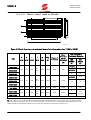
Technical Sheet for LIGHT Applications: Overload up to 120% .............................................21
6.1.2.
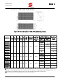
Technical Sheet for STANDARD Applications: Overload up to 140%......................................23
6.1.3.
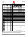
Technical Sheet for HEAVY Applications: Overload up to 175% ...........................................25
6.1.4.
Technical Sheet for STRONG Applications: Overload up to 200% .........................................27
6.2.
Carrier Frequency Setting (IFD SW only) and Peak Currents ..........................................................29
6.3.
OPERATING TEMPERATURES BASED ON APPLICATION CLASSES .................................................31
7. INSTALLING THE EQUIPMENT.................................................................................................... 33
7.1.
Environmental Requirements for the Equipment Installation, Storage and Transport .......................33
7.2.
Air Cooling ................................................................................................................................34
7.3.
Size, Weight and Dissipated Power ..............................................................................................35
7.3.1.
IP20 and IP00 STAND-ALONE Models (S05-S60) 2T Class ...................................................35
7.3.2.
IP20 and IP00 STAND-ALONE Models (S05 – S60) 4T Class.................................................36
7.3.3.
Modular IP00 STAND-ALONE Models (S65).........................................................................37
7.3.4.
IP54 STAND-ALONE Models (S05-S30) 2T Class .................................................................40
7.3.5.
IP54 STAND-ALONE MODELS (S05-S30) 4T Class...............................................................41
7.3.6.
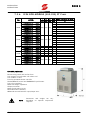
IP54 BOX MODELS (S05-S20) 2T Class ...............................................................................42
7.3.7.
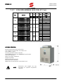
IP54 BOX MODELS (S05-S20) 4T Class ...............................................................................43
7.3.8.
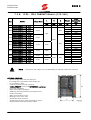
IP24 - IP54 CABINET Models (S15-S65)...............................................................................44
7.4.
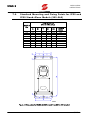
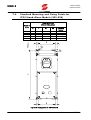
Standard Mounting and Fixing Points for IP20 and IP00 Stand-Alone Models (S05-S60) .................45
7.5.
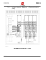
Standard Mounting and Fixing Points for IP00 Modular Stand–Alone Models (S64-S65) .................47
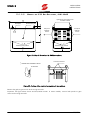
7.5.1.
Installation and Wiring of a Modular Inverter (S65) ..............................................................50
7.6.
Standard Mounting and Fixing Points for IP54 Stand-Alone Models (S05-S30) ..............................51
7.7.
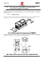
Through-panel Assembly and Fixing Points (Stand-Alone Models S05-S50)...................................52
7.7.1.
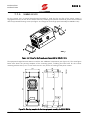
SINUS K S05 ......................................................................................................................52
7.7.2.
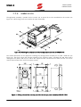
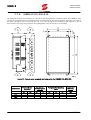
SINUS K S10 ......................................................................................................................53
7.7.3.
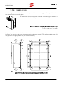
SINUS K S12 ......................................................................................................................54
7.7.4.
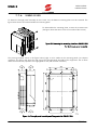
SINUS K S15-S20-S30 ........................................................................................................55
7.7.5.
SINUS K S40 ......................................................................................................................56
7.7.6.
SINUS K S50 ......................................................................................................................57
7.8.
Connections to Control Terminals and Power Terminals (IP20/IP00)..............................................58
7.9.
Connections to Control Terminals and Power Terminals (IP54 Models) ..........................................59
8. WIRING...................................................................................................................................... 60
8.1.
Wiring Diagram (S05-S60)..........................................................................................................61
8.2.
Wiring Diagram for Modular Models (S65) ..................................................................................62
0.
2/191