1
Instruction
Manual
ET200
ENGLISH
ENGLISH
ET200
Instruction Manual
General Specifications
600
480
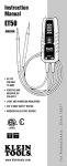
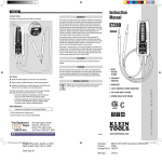
The Klein Tools ET200 is a solid-state electrical tester. It measures AC/DC
voltage, tests continuity, and features a bright LED worklight.
277
240
•
•
•
•
•
•
•
•
•
•
•
•
208
120
48
24
12
•
•
•
•
•
•
• AC/DC
Voltage
to 600V
• Continuity
Function
WARNINGS
To ensure safe operation and service of the tester, follow these instructions.
Failure to observe these warnings can result in severe injury or death.
• CAT IV 600V Safety Rating
• Modern Solid-State Design
www.kleintools.com
For Professionals...Since 1857®
• Worklight
• Light, Vibration, Sound Indicators
Voltage Level Indicators: 12, 24, 48, 120, 208, 240, 277, 480, 600
Voltage Type Indicators: AC, DC Positive, DC Negative
AC Frequency: 45Hz to 66Hz
Maximum Voltage To Earth Ground: 600V RMS
Maximum Measurable Voltage: 600V RMS (displayed by LEDs)
Input Impedance: 15kΩ on connection, up to 150kΩ steady-state.
Continuity: < 270kΩ
Usage Duty Cycle (Above 277V): 1 minute on, 5 minutes off
Accuracy: 70% to 100% of indicated voltage
Battery Type: 3 x AAA
Operating Altitude: 2000m
Relative Humidity:0°C to 30°C (32°F to 86°F) 90%
30°C to 40°C (86°F to 104°F) 75%
40°C to 55°C (104°F to 131°F) 45%
Operating Temperature: 0°C to 55°C (32°F to 131°F)
Storage Temperature: 0°C to 55°C (32°F to 131°F)
Dimensions: 7.375 x 2.375 x 1.25”
Weight: 8.1oz.
Safety: CSA C22.2-1010.1, IEC 61010-1, Pollution Degree II
CAT Rating: CAT IV 600V, CAT III 1000V
• Before each use, verify meter operation by measuring
a known voltage or current.
• Never use the meter on a circuit with voltages that exceed the
category based rating of this meter.
• Do not use the meter during electrical storms, or in wet weather.
• Do not use the meter or test leads if they appear to be damaged.
• Ensure meter leads are fully seated, and keep fingers away from
the metal probe contacts when making measurements.
• Do not open the meter to replace batteries while the probes
are connected to a voltage source.
• Use caution when working with voltages above 60V DC,
or 25V AC RMS. Such voltages pose a shock hazard.
• Shut off and lock out power before testing continuity.
• Always adhere to local and national safety codes. Use individual
protective equipment to prevent shock and arc blast injury where
hazardous live conductors are exposed.
ENGLISH
SYMBOLS
+
–
~
OPERATING Instructions
Positive DC Voltage
Warning or Caution
Negative DC Voltage
Dangerous levels
AC Voltage
Double Insulated Class II
Earth Ground
ETL Certification
Measuring Voltages
Time spent operational at voltages above 277V must be less than
60 seconds, with a cool-off time of at least 5 minutes.
Tester will turn on automatically when voltage is applied.
600
CAT III
CAT IV
Designed for transient protection
on indoor measurements at
installations connected directly
to the primary source. Examples
include distribution panels and
lighting systems in large buildings.
Designed for transient protection
on outdoor measurements taken
at the primary supply voltage
source. Examples include outdoor
overhead or underground utility
service and electricity meter.
480
277
240
208
120
48
24
12
120
48
24
12
Feature Details
Indicators
Lights
• LEDs light up numerical voltage level indicators,
as well as AC and DC + or DC – indicators.
• Continuity LED will light up on detection.
• Voltage detection will function without batteries installed.
Vibration
• Instrument will vibrate in the presence of voltage
measurements greater than 48V.
• Vibration will function only with batteries installed.
Sound
• Instrument will emit a tone in the presence of voltage
measurements greater than 48V.
• Instrument will emit a tone on detection of continuity.
• Sound will function only with batteries installed.
Accuracy
Accuracy of indicator lights is 70% to 100% of the voltage displayed
to account for normal variations in supply voltage.
Worklight
Press the light bulb button above the Klein Tools logo to toggle the
worklight on and off.
AC Voltage Measurement
600
480
277
240
208
120
48
24
12
120
48
24
12
Ghost Voltages
The approximate input resistance of 15kΩ will reduce the possibility of
false readings due to ghost voltages on de-energized lines.
Lead Spacing
Molded lead holders on the back of the ET200 are spaced correctly
to test tamper-resistant outlets.
DC Voltage Measurement
ENGLISH
Continuity Testing
Continuity is indicated at less than 270kΩ of resistance.
600
480
277
240
600
208
120
48
24
12
Warranty
This product is warranted to be free from defects in materials and workmanship
for a period of two years from the date of purchase. During this warranty period,
Klein Tools has the option to repair or replace or refund the purchase price of
any unit which fails to conform to this warranty under normal use and service.
This warranty does not cover damage which occurs in shipment or failure which
results from alteration, tampering, accident, misuse, abuse, neglect, or improper
maintenance. Batteries and damage resulting from failed batteries are not
covered by warranty. A purchase receipt or other proof of original purchase date
will be required before warranty repairs will be rendered.
Any implied warranties, including but not limited to implied warranties of
merchantability and fitness for a particular purpose, are limited to the express
warranty. Klein Tools shall not be liable for loss of use of the instrument or other
incidental or consequential damages, expenses, or economic loss, or for any
claim or claims for such damage, expenses or economic loss.
Some states or countries laws vary, so the above limitations or exclusions may
not apply to you. This warranty gives you specific legal rights, and you may also
have other rights which vary from state to state. If your Klein product requires
repair or for information on how to exercise your rights under the terms of this
warranty, please contact Klein Tools at 1-800-553-4676.
CLEANING
Clean the instrument by using a damp cloth. Do not use abrasive cleaners or
solvents.
STORAGE
GFCI Testing
Remove the batteries when instrument is not in use for a prolonged period of
time. Do not expose to high temperatures or humidity. After a period of storage
in extreme conditions exceeding the limits mentioned in the Specifications
section, allow the instrument to return to normal operating conditions before
using it.
Check the GFCI Receptacle user manual for more information.
Disposal / Recycle
Always contact a qualified electrician to resolve wiring problems.
Operate the Push Button on the GFCI Receptacle. If the GFCI circuit does not trip, the receptacle is not operating properly.
Caution: This symbol indicates that equipment and its accessories
shall be subject to a separate collection and correct disposal.
To test the functionality of a Ground Fault Circuit Interrupter receptacle,
apply leads to the hot and ground terminals for 7 seconds.
• If the GFCI receptacle is wired properly, power to the circuit
will go out and the ET200 will stop indicating voltage.
• If the GFCI receptacle is wired improperly, power to the circuit
will remain and the ET200 will continue to indicate voltage.
To resolve an issue, contact a qualified electrician.
Battery Replacement
Batteries are not required for visual voltage indication.
1.Remove test leads from voltage source.
2.Unscrew battery cover and replace 3xAAA batteries.
CUSTOMER SERVICE
KLEIN TOOLS, INC.
450 Bond Street
Lincolnshire, IL 60069
1-877-287-6603
1-800-553-4676
www.kleintools.com
139575T