1
lllllllllllllllllllllllllllllllllllllllllllllllllllllllllllllllllllllllllll
.
USOO5291285A
United States Patent [19]
[11] Patent Number:
Yokoyama et al.
[45]
[54] TELEVISION SIGNAL LEVEL METER
[75] Inventors: gzsgglr¥rlgfgggiaolgéilhgf
Kanaéawa all of Jar’mn
_
’
[73] Assigneez
Date of Patent:
5,291,285
Mar. 1, 1994
OTHER PUBLICATIONS
“Bandscope Technology of Marantz’ Wide-Band Re
ceiver AX700”, HAM Journal, No. 59, 1989, pp. 62-67.
_
Leader Electronics Corp. TV-VHF/UHF/DBS IF
Leader Electronics, Yokohama,
Level Meters 1939 catalog,
Japan
Meters WINDOW II and WINDOW LITE catalog,
[21] Appl. No_; 890,135
1991 (exact date unknown).
.
Catalog and User’s Manual of “TV Field Strength Mea
[22] PM‘
May 29’ 1992
[30]
Foreign Application Priority Data
suring Instrument Model NLC-W901” sold by Nippon
Antenna Co. (exact date of publishing unknown).
May 31, 1991 [JP]
Japan ................................ .. 3-129567
[51] Int 01 5 ......................................... .. 110m 17/00
[52] US. Cl. .................................. .. 348/180; 348/185;
Primary Examiner—Victor R. Kostak
Am’mey' 488"” 0’ ?lm-Fish 8‘ Ridmds‘m
[57]
ABSTRACT
[58] Field of Search
A television signal level meter is provided which is
358/139
"""""""""""" "
[55]
HOJN i-l/od '
capable of simultaneously displaying levels for a multi
tude of television channels in a scale having a variable
dynamic range. The television meter includes a level
References Cited
U_5_ PATENT DOCUMENTS
image forming means for displaying signal levels of a
.
multitude of channels, a scale forming means for form
lssirgslgtegl """"""""""" " 358/139 X
5:l66:79l 11/1992 Crawford ...................... .. ass/139
ing a scale suitable for simultaneously displaying the
Signal levels of the channels, and an image forming
5,216,492 6/1993 Borrough m1. ............ .. ,358/139 x
means for displaying channel numbers associated with
the channels.
FOREIGN PATENT DOCUMENTS
I 8 Claims, 6 Drawing Sheets
55-150572 10/1980 Japan .
a
(MULT l )
( WARNING
..-.".'
:AlO ‘l/YOKOYAMA
)
~-'~ '-
TIME
UP
V 91. 25MHZ
76.1
dBuV
V
1 'oiniulii. !
I
US. Patent
Mar. 1,1994
Sheet 3 of 6
5,291,285
Ewom
5
E .
g
5
u
_“5
A
m2
F
_
.u:
.>
23.;
Em:
S;
>
_. _
E.
S
Egg
nItNhv:
US. Patent
Mar. 1, 1994
Fig. 4A
Sheet 4 of 6
5,291,285
MULTI CHANNEL
DISPLAY FLOW
@
SET
CH1 ~ n
SET SP-CH
FROM STEPS
722. 732
< DISPLAY FIXED IMAGES )-»7°‘
,
CH X=1
v- 702
CALL _AND SET CH FREQUENCY ~1-704
T
SET P.ATTS
CALCULATE
I
FETCH LEVEL FOR SP-CH
T
TO STEP 716
US. Patent
Mar. 1, 1994
Sheet 5 of 6
5,291,285
Fig. 45
FROM STEP 714
I
CALCULATE DISPLAYED p1716
POSITION
To STEP 702
f
X + I
DISPLAY LEVEL BARS
718
6ND NUMERICAL VALUES
4-722
t
720
YES
NO
CALCULATE LEVEL
724
DIFFERENCE FOR I
CHI ~ n
I
DETERMINE
I726
I
CALCULATE
728
SCALE RANGE
MEDIAN LEVEL
I
TO STEP 702
DETERMINE MEDIAN
I
LEVEL VALUE
x + I
I
E
732
730
f
I
< DISPLAY SCALE
I
73‘
5,291,285
1
TELEVISION SIGNAL LEVEL METER
BACKGROUND OF THE INVENTION
1. Field of the Invention
2
SUMMARY OF THE INVENTION
In view of the above-mentioned problems, an object
of the present invention is to provide a TV signal level
meter which is capable of measuring and simultaneously
This invention relates to a television (TV) signal level _ ' indicating the levels of signals for a multitude of TV
meter (electric ?eld strength meter), and more particu
channels.
larly to a meter of this kind for use in measuring and
displaying an electric ?eld strength of a radio wave of
each television channel included in the VHF/UHF
meter according to the present invention which com
ranges or the like.
television channels, the levels of which are to be mea
2. Prior Art
,
conventionally, a TV signal level meter or a spec
trum analyzer is used for measuring an electric ?eld
strength of a radio wave received in a TV channel. The
TV signal level meters may be classi?ed into a single
channel type and a multi-channel type. One such single
channel type TV meter is a VHF/UHF signal level
meter LFC-945 manufactured by the present assignee
The above object is realized by a TV signal level
prises: (a) channel setting means for setting a plurality of
sured; (b) level measuring means coupled to receive an
input for detecting the level of a signal received in each
of the plurality of television channels from the input and
storing the detected signal levels; and (0) display means
responsive to the plurality of television channels from
the channel setting means and a plurality of said stored
and indicates electric ?eld strength levels of up to a
signal levels from the level measuring means, including:
(cl) a plurality of level image display regions for dis
playing signal levels for the respective channels in a
given form of image in a predetermined scale; and (c2)
a plurality of channel number image display regions for
displaying channel numbers associated with the respec
tive channels, the positions of the plurality of channel
number image display regions being correlated to the
predetermined number of channels (for example seven
plurality of level image display regions, respectively.
which is adapted to measure and indicate an electronic
?eld strength level of a selected single channel. On the
other hand, one type of multi-channel type TV signal
level meter is MODEL NLC-W90l manufactured by
Nippon Antenna Co., which simultaneously measures
channels). A spectrum analyzer, though not exclusively
According to the present invention, the display
employed for the measurement of TV signal levels, can
also be used for measuring the electric ?eld strength
magnitudes of TV channels since it can display the
levels of received signals within a certain frequency
range.
Since the above-mentioned single channel type TV
signal level meter cannot simultaneously display elec
tric ?eld strength levels of a plurality of channels, it
means may further include display control means which
takes a long time to measure the levels of a large number
means responsive to the plurality of channels for form
of channels. In condominiums and apartment complexes
comprises: (a) scale forming means responsive to the
plurality of stored signal levels for detecting maximum
and minimum values thereof and forming the predeter
mined scale having a range depending on the values; (b)
level image forming means responsive to the plurality of
stored signal levels for forming the level images repre
senting the signal levels; and (c) number image forming
ing number images representing the numbers for the
and so on, it has been required that outputs from an
channels, respectively.
installed common antenna to respective dwelling units 40
According to the present invention, the TV meter
must have signal levels not lower than a predetermined
may further comprise means for specifying in the plural
value at any channel. In meeting such a requirement,
ity of channels at least one channel the signal level of
adjustment of the antenna by using a single channel type
which is to be displayed by a numerical value. The
TV meter requires a great deal of labor. Further, since
display means may further comprise at least one numeri
the number of channels which require measurements of 45 cal level value image display region for displaying a
signal levels has been increasing with the recently wide
numerical level value image of a channel. Also, the
spread installation of a city-type CATV or the like, the
display
control means may comprise numerical level
labor for measuring and checking signal levels of these
value
image
forming means responsive to a speci?ed
channels becomes immense.
This problem can be alleviated to some extent by the 50
foregoing multi-channel type TV signal level meter
MODEL NLC-W90l. This TV level meter, however,
divides a measurable level range into a high region
channel from the specifying means for forming an
image representing the numerical value of the stored
signal level of the speci?ed channel.
BRIEF DESCRIPTION OF THE DRAWINGS
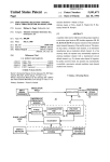
FIG.
1 is a block diagram illustrating the basic con?g
has a narrow dynamic range for the simultaneous dis 55
uration
of a TV signal level meter according to the
play of measured results. Speci?cally, if there is a large
invention;
difference in level among channels, the measured levels
FIG. 2 is a circuit block diagram illustrating a TV
of all channels cannot be displayed at one time. Thus,
signal level meter which embodies the basic con?gura
the TV signal level meter of this model is not suitable
tion of the TV signal level meter shown in FIG. 1;
for the requirement of the collective residence. The
FIG. 3 is a diagram illustrating a front panel of the
model also suffers a drawback that selection and change
(60-100 dBp.) and a low region (30-70 dBp.) and thus
of channels to be measured take much time.
If a spectrum analyzer is employed for measuring TV
channel signal levels, the levels of all signals present
TV signal level meter shown in FIG. 2 including a
control panel and a screen;
FIGS. 4A and 4B are flow charts illustrating multi
within a certain frequency range are displayed. Due to 65 channel display ?ow executed by a microcomputer
to be measured. There is another drawback that the
constituting a control circuit shown in FIG. 2; and
FIG. 5 is a diagram illustrating another display on a
device itself is very expensive.
screen shown in FIG. 3.
this, it is inconvenient to find the signals of TV channels
3
5,291,285
DESCRIPTION OF THE PREFERRED
EMBODIMENT
An embodiment of the present invention will herein
after be described with reference to the accompanying
drawings.
4
composed of a microcomputer with a memory; a key
board 8; and a display 9. The tuner 6, which is a conven
tional one having an auto range function, has two pro
grammable attenuators {P.A'I'I's) for the auto range
function. More speci?cally, the tuner 6 includes a radio
frequency (RF) programmable attenuator (PATT) 600
Referring to FIG. 1, the basic con?guration of a TV
connected to an input terminal; an RF tuner circuit 602
signal level meter A according to the invention is
shown. The TV level meter A comprises a channel
receiving an attenuated output from the attenuator 600;
a mixer circuit 604 connected to the output of the RF
(CH) signal level measuring means 1, connected to an -
tuner 602; an intermediate frequency (IF) programma
input terminal adapted to receive a signal input; a dis
ble attenuator (PATT) 606 connected to the output of
the mixer 604; an IF ampli?er/detector 608 receiving an
attenuated output from the IF P.A'l'l‘ 606; and a level
comparator circuit 610 receiving an output from the IF
specifying at least one channel whose level value (LV) 5 ampli?er/detector 608. In order to control the circuits
measured is to be numerically displayed; and an input
602 and 604, the tuner 6 is further provided with a pro
means 5 for other inputs.
grammable counter 612; a phase comparator connected
The level measuring means 1 comprises a channel
to receive an output from the programmable counter
signal level detector means 10; a multi-channel signal
612 and an output from a reference frequency (f);) cir
play means 2 connected to the measuring means 1; a
setting means 3 for designating numbers of a multitude
of channels to be measured; a specifying means 4 for
level memory 12; and a channel selector means 14. The
selector means 14 receives a multitude of designated
channel numbers from the setting means 3 and selects
one of the designated channels in each measurement
cuit 614 (for example, fR=5O KHz); a charge pump
circuit 618 coupled to receive an output from the phase
comparator for generating a DC voltage; and a local
oscillator circuit 620 coupled to receive the DC voltage
outputted from the charge pump circuit 618 to apply an
nel numbers to the detector means 10. When an output 25 oscillation output to a second input of the mixer circuit
from the selector means 14 is received, the detector
604. The DC voltage output generated by the charge
means 10 detects and outputs the level of the compo
pump circuit 618 is used to determine a tuned frequency
cycle in order to sequentially output the selected chan
nents in the received input, which are in a frequency
for the tuner circuit 602 as well as an oscillation fre
band associated with a selected channel. The level
quency f)_ for the local oscillator circuit 620.
30
memory 12 then stores the detected level.
Speci?cally, the programmable counter 612 divides
The display means 2 generally consists of a display
control means 20 and a display unit 22. The display
control means 20 includes four image forming means
200, 202, 204 and 206, as shown in FIG. 1, and a screen
the oscillation frequency f1, from the local oscillator
circuit 620 by a division ratio supplied from the control
circuit 7 and applies the divided output to the phase
comparator
616. The phase comparator 616 adjusts the
image forming means 208 which synthesizes images 35
from the four image forming means to generate a screen
image to be displayed. Speci?cally, the scale forming
means 200 receives a multitude of detected levels stored
DC voltage generated by the charge pump circuit 618
in such a direction that the difference between the fre
quency of the divided output and the reference fre
quency fR is decreased, thereby controlling the oscilla
in the level memory 12 and forms the image of a scale
suitable for displaying the multitude of detected levels. 40 tion frequency of the local oscillator 620 to generate a
local oscillation frequency dictated by the division ra
The multi-channel level image forming means 202 re
tio.
ceives the detected levels stored in the level memory 12
and a multitude of designated channel numbers from the
For the tuner 6 thus constructed, the control circuit 7
supplies the counter 612 with a division ratio associated
setting means 3 to form images representing the magni
tudes of levels for the respective channels. Preferably, 45 with the frequency of a TV channel to be tuned, as
stated above, as well as the two programmable attenua
such images may include bars each having a length
tors 600, 606 with outputs for specifying respective
corresponding to each level. The SP-CI-I numerical LV
attenuation ratios for the auto range operation. In the
image forming means 204 receives the detected levels
embodiment, the level comparator circuit 610 deter
stored in the level memory 12 and a speci?ed channel
(SP-CH) number from the specifying means 4, and fet 50 mines whether or not the IF output from the circuit 608
is within a dynamic range of 9 dB and supplies the
ches the detected level for the specified channel to form
control circuit 7 with a signal (via a line a) indicating
a numerical image indicative of the level value (LV) of
“within the range", “above the range” or "below the
the detected level. The last image forming means 206 is
range” together with a detected level (via a line b).
connected to the setting means 3, the specifying means
4 and the input means 5. The means 206 forms relatively 55 When a signal other than that indicating “within the
range” is outputted, the control circuit 7 changes a set
?xed images (for example, images for channel numbers
of attenuation ratio specifying signals for the two
and a channel specifying mark, and other character/
P.A'1'1‘s 600, 606, as will be later described.
graphic images) which constitute a screen image to
The control circuit 7 is provided with the keyboard 8
gether with the aforementioned images.
When the foregoing formed images are received, the 60 for a variety of inputs. The keyboard 8 has keys as seen
on a control panel 80 in FIG. 3. The display 9 con
screen image forming means 208 synthesizes them in a
nected to the control circuit 7 has a LCD (liquid crystal
certain selected format to form a screen image which is
display) screen 90 also shown in FIG. 3. The screen 90
is divided into a scale display region 91; a region 92
22 displays it on the screen thereof.
Referring now to FIG. 2, a TV signal level meter 65 within the scale display region 91 for displaying level
outputted to the display unit 22. Then, the display unit
AA, which embodies the basic con?guration of FIG. 1,
will be described hereinafter. The TV level meter AA
shown in FIG. 2 comprises a tuner 6; a control circuit 7
images, such as bars 97, associated with respective TV
channels; a region 93 below the region 92 for displaying
TV channel numbers; a region 94 for displaying digital
5
5,291,285
6
uses MEASURE keys and EDIT keys and comprises
the following steps as will be understood from the fore
values and other data for a speci?ed channel (SP-CH);
and a region for displaying other data items.
Keys on the keyboard 8 which are involved with the
invention will be described. A “MULTI/SINGLE”
key is used to switch between a multiple-bar graph
going explanation of the keys: 1) Selecting a channel
group to be changed by the PRG RECALL key; 2)
Selecting a CH name item by using the ITEM key
(changing the display from PRGn to TMPn); 3) Posi
display provided in accordance with the invention, and
a single-bar graph display. A “PRG RECALL” key
tioning a cursor (mark 95) to a location (within the
region 93) to be changed by the CHANNEL key; 4)
Changing a channel by the CHARACTER key; and 5)
calls one of four channel groups PRGl-PRG4 in the
multi-channel display. In FIG. 3, the channel group
PRGZ is selected. Each group includes eight channels.
Programming the channel change in a selected one of
“CHANNEL” keys are used to specify one among
designated channels (i.e. a channel surrounded by a
PRGI-PRG4 by pressing the PRG WRITE key and
rectangle 95 or Channel 1 in FIG. 3) in order to display
a digital level value thereof in the multiple-bar graph
pleted. A third method (a method of changing the set
ting of any of channels CH 1-CH 8 from a channel of a
display. “ITEM” keys select an item to be edited among
items, i.e. a received channel, PICTURE/SOUND (the
table) also uses the groups of MEASURE keys and
one of the function keys after the change has been com
frequency in a selected channel table to one not in the
initial character of “PICTURE” or “SOUND” is added
after a channel number, such as 1:P or 4:P when PIC
TURE is selected), a frequency and so on. “POSI
TION” keys are used to select a position to be modi?ed 20
in a numerical value or a character string when an item
selected by the “ITEM" key is a channel name, a fre
quency and so on represented by such a character string
EDIT keys in a manner similar to the second method
and comprises the following steps: 1) Selecting a chan
nel group by the PRG RECALL key; 2) Positioning the
cursor to a location to be changed by the CHANNEL
key; 3) Selecting a frequency item by the ITEM key; 4)
Positioning the cursor to a digit to be changed by the
POSITION key; 5) Changing the value of the digit by
the CHARACTER key; 6) Changing a CH name item
to modify the contents of the position selected by the 25 by the same key manipulations as the steps 3), 4) and 5)
after the value has been changed; and 7) Pressing the
“POSITION” key. A “CH SEARCH” key is used to
PRG WRITE key after the change of the CH name
automatically measure signal levels of all of previously
item has been completed. Then, the change is pro
selected channels in the VHF and UHF bands, select 32
grammed in one of PRG1-PRG4 by the same manipula
channels which exhibit larger signal levels, store the
or a numerical value. “CHARACTER” keys are used
signal levels of the selected channels, and display the
signal levels of all eight channels at a time in the multi
ple-bar graph mode. An “AUTO SCALE” key alter
nately switches between auto and manual switching for
a level measurement range. A “DATA STORE” key is
used to store data representing measured levels in the
memory (which is capable of storing up to four sets of
measured level data for groups of eight channels). A
“FUNCTION CALL” key enables keys denoted
“F-l”, “F-2", “F-3”, “F4” and “F5” (including the
same keys as the foregoing ones) to select one from a
variety of other functions.
Referring now to FIGS. 4A and 43, a multi-channel
30 tion as the second method.
Referring back to FIG. 4A, at step 701, relatively
?xed images (for instance, channel numbers 1:P . . .
42:P, PRG2, the rectangular mark 95 indicating a speci
?ed channel, and other character and numerical images
shown in FIG. 3) are displayed. Then, a channel num
ber X is set to “l” at step 702, and then a level measu
ring/display processing for the channel 1 by a group of
the subsequent steps 704-720 is executed. Speci?cally,
?rst at step 704, the frequency of the TV channel 1 (i.e.
picture frequency in the instance shown in FIG. 3) is
searched from a channel-frequency table stored in the
memory, and a division ratio corresponding to the fre
quency is outputted to the counter 612 so that the tuner
set in a receiving state for the channel 1. Next, at step
display ilow executed by the control circuit 7 will be
described hereinafter.
In the multi-channel display ?ow shown in FIG. 4A, 45 706, the programmable attenuators (P.A'I"I‘s) 600, 606
it is assumed that channels CH l-CH n (in this instance,
channels CH 1—CH 8 correspond to TV channels 1, 3, 4,
are adjusted so that the received TV signal level of the
channel 1 falls within the predetermined dynamic range
of 9 dB mentioned before. Speci?cally, the P.ATT 600,
6, 8, 10, 12 and 42, respectively, in a group PRGZ) and
which can be set, for example, to one of three ratios of
a numerical-level-value displayed channel (channel CH
1 in this instance) have been set at the ?rst step 700. 50 0, 30 and 50 dB, and the other P.ATT 606, which can be
set, for example, to fourteen ratios from 0 to 65 dB with
Here, the method of setting channels CH I-CH 8 will
5 dB steps, are adjusted to set a 65 dB ratio (i.e. 30 dB
be brie?y explained. As a ?rst method, channels CH
at P.ATT 600 plus 35 dB at P.ATT 606) which usually
1-CH 8 are set by the foregoing “CH SEARCH” key in
correlates to the middle of a displaying dynamic range
the following manner: 1) Every eight of the 32 channels
selected by the key manipulation as described above are 55 of 100 dB. Then, if the TV signal level is within the
predetermined 9 dB dynamic range, the 65 dB ratio is
stored in memories TMPs (TEMPORARY) 14 in the
frequency increasing order; 2) One of TMPl-TEP4 to
be programmed is selected by the “PRG RECALL”
key; 3) A “PRG WRITE” key is pressed; 4) One of the
determined to constitute a proper range, and the ?ow
from one channel to another in a selected channel table)
- ued while switching an attenuation changing amount to
proceeds to the next step 708. On the contrary, if it is
not in that predetermined dynamic range, the attenua
function keys F-1-F-4 respectively for specifying the 60 tion rate is decreased by 30 dB when it is below the
predetermined dynamic range while increased by 30 dB
channel groups PRG1-PRG4 is pressed to program a
when above the dynamic range. Then, it is again deter
group of channels stored in the selected memory TMP
mined whether or not the TV signal is within the prede
into a channel group memory PRG corresponding to
termined dynamic range. If the TV signal is still out of
the pressed function key. By repeating the above steps
1)-4), the channel groups PRGl-PRG4 can be pro 65 the range after the adjustment, the attenuation ratio is
likewise changed with a changing amount of 15 dB.
grammed. A second channel setting method (a method
Thus, the adjustment of the attenuation ratio is contin
of changing the setting of any of channel CH 1-CH 8
7
5,291,285
10 dB and 5 dB, until the TV signal level falls within the
predetermined dynamic range. In this manner, an ap
propriate range for each channel is determined by
changing the attenuation ratio maximum ?ve times.
(Finally determined attenuation ratios for a group of
8
received at the TV channel 10 is above 120 dB, a white
I
triangular sign directed upward is added on the bar for
the TV channel 10. Thus, even if levels of signals at
different TV channels largely fluctuate, they are all
5 displayed at the same time.
_
While an embodiment of the invention has been de
channels at the last measurement cycle are stored and
scribed, the following changes are possible. First, the
image representing a level of each TV channel may be
another graphical representation other than the bar
then called to be used for corresponding channels at the
subsequent measurement cycles. If the TV signal of a
channel does not fall within a proper range set by the
called attenuation ratio, the ratio is set to the above
chart as employed in the illustrative embodiment. Se
mentioned 65 dB, and then the attenuation ratio is
condly, although the number of bars simultaneously
changed as described above.)
displayed on the screen is determined to be eight, this
number may be changed if necessary as long as the level
I
When the TV signal level of the channel 1 enters the
proper range, the level from the level comparator 610 is
read at the next step 708 and stored at step 710. Then, at
step 712 the stored level is combined with the total
image display region on the screen permits. It is also
possible to change the number of bars displayed on the
screen depending on the number of designated chan
nels. Further, while the number of channels whose
signal levels are digitally displayed is one in the forego
ing embodiment, the number of such channels may be
increased if necessary. Also, the digital values of levels
attenuation ratio set at step 706 to calculate a detected
level of the TV signal of the channel 1. Since the chan
nel 1 is a speci?ed channel, the detected level of the
channel 1 is fetched at step 714 (its digital value is 76.1
dBuV in the instance shown in FIG. 3). Next, at step
of all channels may be displayed on the screen.
716, a position on the screen for displaying a bar 96
According to the TV signal level meter described
(FIG. 3) representing the detected level of the channel
above in detail, a level of a signal received at each TV
channel is individually measured by adjusting the pro
1 is calculated from the value computed at step 712 and
a scale. The bar 96 and a corresponding digital value are 25 grammable attenuators, so that the measurement and
display can be carried out over a wide dynamic range,
displayed at step 718. It should be noted that the level
bars (including 96, 97, 98), the digital level value of a
thereby making it possible to graphically display the
speci?ed channel and the scale described hereinafter are
levels of signals for a maximum number of TV channels
displayed in a time-division manner.
displayable on the screen at the same time. It is there
At step 720, since X (=1) is smaller than n (= 8), the
value X is incremented by one at step 722, and then the
above described process is repeated for the channel CH
2 (i.e., the TV channel 3 in this instance). After the
measuring/display loop has been repeated n times and
the n-th bar (i.e. bar for TV channel 42 in this instance) 35
fore possible to adjust equipment to be measured such as
an antenna while simultaneously con?rming the levels
of all displayed channels. Also, the frequency of a chan
nel switching operation can be minimized and a manual
switching of the attenuators can be made unnecessary,
has been displayed, an answer at step 720 is NO. Then,
a scale determination/display process is executed at
measurement.
thereby facilitating manipulations of the meter during
What is claimed is:
steps 724-731.
Explaining next the scale determination/display pro
cess, at the ?rst step 724, the difference between the
maximum and minimum values of the detected levels
1. A television signal level meter comprising:
(A) channel setting means for setting a plurality of
for the channels CH 1-CH n is calculated. Then, a scale
(B) level measuring means coupled to receive an
range is determined corresponding to the magnitude of
the level difference. For example, if the difference is less
than 12 dB; between 10 and 30 dB; between 25 and 60
dB; and between 50 and 100 dB, the range is established
with 2 dB/DlV; 5 dB/DIV; l0 dB/DIV; and 20
dB/DIV, respectively. When the range is changed, a
received in each of said plurality of television chan
nels and storing the detected signal levels; and
(C) display means responsive to said plurality of tele
vision channels from said channel setting means
and a plurality of said stored levels from said level
television channels, the levels of which are to be
measured;
input for detecting in said input the levels of signals
45
hysteresis operation is performed. At the next step 728,
a median level is calculated from the maximum and
minimum level values, and the value of the median level
of the scale is determined at step 730. The data obtained
at the above steps 724-730 are displayed in the scale
display region 91 at step 731. Finally at step 732, the
value X is incremented by one (whereby the value X is 55
returned to 1), followed by the flow returning to step
702. The above described process is repeated for the
channels CH 1-CH n until an interrupt occurs due to a
change of the channel group PRG, power-off, or the
like. During the above process is executed, when the
meter of the present invention is used in adjusting the
orientation of an antenna, a bar display, a digital value
measuring means, including:
i) a plurality of level image display regions for
displaying signal levels for the plurality of chan
nels in a predetermined scale; and
ii) a plurality of channel number image display
regions for displaying channel numbers associ
ated with the plurality of channels, respectively,
the positions of said plurality of channel number
image display regions being correlated to the
positions of said plurality of level image display
regions, respectively,
iii) display control means comprising:
(a) scale forming means responsive to said plural
ity of stored signal levels for detecting maxi
display and the scale change, for example, as shown in
mum and minimum values thereof and form
FIG. 5, each time the antenna is moved. Referring to
FIG. 5, since the level of a signal received at the TV 65
channel 3 is below 20 dB a triangular sign directed
downward is added to the bar representing the detected
level of the channel 3. Also, since the level of a signal
ing said predetermined scale having a range
depending on the maximum and minimum
values;
(b) level image forming means responsive to said
plurality of stored signal levels for forming
5,291,285
said level images representing said signal lev
els; and
(c) number image forming means responsive to
said plurality of channels for forming number
images representing the numbers of said chan
5
nels.
2. A television meter according to claim 1 further
10
image display regions in response to changes in the
signal levels of the plurality of channels.
7. A method of measuring and simultaneously indicat
ing signal levels for a plurality of television channels
comprising the steps of:
(a) setting a plurality of television channels, the levels
of which are to be measured;
comprising means for specifying in said plurality of
(b) receiving an input signal;
(0) detecting in the input signal the level of signals
channels at least one channel the signal level of which is
to be displayed by a numerical value,
wherein said display means further comprises at least
one numerical level value image display region for
displaying a numerical level value image of a chan
received in each of the plurality of television chan
nels;
(d) storing the detected signal levels;
(e) displaying signal levels for the plurality of chan
nel; and
wherein said display control means comprises numer 15
ical level value image forming means responsive to
a speci?ed channel from said specifying means for
forming an image representing the numerical value
of said stored signal level of the speci?ed channel.
nels in a plurality of level image display regions;
and
(f) displaying channel numbers associated with the
plurality of channels in a plurality of channel num
ber image display regions,
wherein the step of displaying signal levels further
comprises the steps of:
(i) scaling the detected signal levels to determine a
3. A television meter according to any of claims 1-2,
wherein said level image forming means forms a num
ber of level images corresponding in number to the
display scale, and
plurality of channels.
(ii) displaying said detected signal levels in accor
4. A television signal level meter according to claim
dance with said display scale.
25
1 wherein said display means further comprises at least
8. The method of claim 7 further comprising the steps
one channel image display region for displaying a chan
of:
nel number and frequency of a channel.
(g) selecting a speci?c channel from the plurality of
5. A television signal level meter according to claim
2, further comprising data storage means for storing
30
data representing measured levels in a memory.
6. A television signal level meter according to any of
claims 1-2 wherein said display means updates the level
35
45
50
55
65
channels, and
(h) displaying a channel number and channel fre
quency of the speci?c channel.
$
‘
t
i
i
UNITED sTATEs PATENT AND TRADEMARK OFFICE
CERTIFICATE OF CORRECTION
PATENT NO.
:
5,291,285
DATED
:
March 1, 1994
|NVENTOR(S) :
Itoshi Yokoyama et at
It is certi?ed that error appears in the above-identi?ed patent and that said Letters Patent is hereby
corrected as shown below:
On the title page, Item [73] Assignee: "Leader Electronics,
Yokohama, Japan" should read ——Leader Electronics Corp.-—
Signed and Sealed this
First Day of November, 1994
Am"
6W4 W
BRUCE LEI-[MAN
Attesting Officer
Commissioner of Patents and Trademarks