1
llllllllllllllllllllllllllllllllllllllllllllllllllllllllllllllllllllll
USOO5541671A
United States Patent [191
[11] Patent Number:
[45] Date of Patent:
Pugel
5,541,671
Jul. 30, 1996
[54] USER CHANNEL SELECTION CONTROL
FOR A VIDEO RECIEVER RF MODULATOR
Assistant Examiner—Nathan J. Flynn
Attorney, Agent, or Firm-Joseph s. Tripoli; Eric P. Her
[75] Inventor: Michael A. Pugel, Noblesville, Ind.
man“; Ronald H‘ Kurdyla
[73] Assignee: Thomson Consumer Electronics Inc.,
Indianapolis, Ind.
[57]
[211
22
App} No . 384 299
F1 d‘
F b 6 1995
A satellite video receiver (12) for providing output signals to
a television signal receiver (52) includes apparatus (10, 15,
[ 1
[51]
1e '
e ' ’
Int. (31.6 ..................................................... .. H04N 5/40
16,20, 45, 60, 65, 70) for operator selection of the modulator
Output channel frequency of the satellite receiv?r. The Opera_
.
.1
,
"""""""""""""""" "
""""""""""
[56]
33582323595
tor may select a modulator main channel, or an alternative
734’ 724 731’
manufacturer pre-set modulator default channeL In a first
recovery mode, the operator may automatically replace an
existing modulator channel with a manufacturer pre-set
default channel, e.g., if a chosen main channel is forgotten.
References cued
U.S. PATENT DOCUMENTS
4 , 336 , 555
6/1982 Wine ..................................... .. 358/335
15°“? - ~ - - -
,
,
ax
5,467,141
er
ABSTRACT
-
.. .. . ..
In another recove Ty mode, the 0 P erawr may automatically
re-establish a previously selected modulator main channel
. . . ..
11/1995 Ligertwood ....................... .. 348/724 X
recalled from memory
OTHER PUBLICATIONS
Owner’s Instruction Manual for the Samsung VS—330 Video
Cassette Recorder, Cover and pp. 7-8 and 11-12.
Owner’s Instruction Manual for the Samsung XD —3500 8
mm Video Cassette Recorder, Cover and pp. 5—6 and 17-18.
5 Claims, 2 Drawing Sheets
Primary Examiner—Victor R. Kostak
MODULATOR
INPUT
‘
INPuT
SIGNAL
PROCESOR \
RF
OUTPUT TELEvIsION
> MOouLATOR-—>—> SIGNAL
RECEIVER
\
N
50
52
14
REFERENCE
2
l
FREQUENCY
SOURCE
45
_
|
_
_
_
_
_
PHASE
I
20
SWITCH
NETWORK
30
I
‘——---——---—-————>
“m
_
_
_
_
_
_
a
COMPENSATlON
DETECTOR ->
PHASELOOP
LOCKE6:
FD
_
_
_
_
_
_
.1
VOLTAGE
AND
—> CONTROLLED
AMPLIFICATION
f OSCILLATOR
40
35
W DIVIDER
<—
MICROPROCESSOFI
USER MENU
4———-——--— CONTROL
SYSTEM
\
15
1g
ANO DISPLAY
|
I
I
I
l
5,541,671
1
2
USER CHANNEL SELECTION CONTROL
FOR A VIDEO RECIEVER RF MODULATOR
modulator channel, or the modulator channel is changed
without his knowledge. These situations are more likely to
arise with video receivers that use operator adjustable modu
lators with a wide, continuously adjustable frequency selec
FIELD OF THE INVENTION
tion range. In such a case there is a greater opportunity for
an operator to erroneously set a modulator channel, or to
This invention is related to the ?eld of video signal
receiving apparatus. In particular, the invention concerns a
forget a previously selected modulator channel. The operator
system for selecting an RF modulator output channel in a
may then set the television receiver to an incompatible
channel. As a result the television tuner will not be set to the
direct broadcast satellite receiver, for example.
10
BACKGROUND OF THE INVENTION
carrier frequency of the video receiver modulator, and the
television receiver will not display a valid picture. The
operator may interpret this result as an equipment failure.
Video signal receivers such as direct broadcast satellite
receivers and video cassette recorders (VCRs) provide video
output signals as Radio Frequency (RF) modulated signals
SUMMARY OF THE INVENTION
to a television receiver, for example. The carrier frequency
selected for this RF modulation in the United States, for
example, is usually the broadcast channel 3 or channel 4
cable television (CATV) carrier frequency. Selection of one
of these channels is typically accomplished by means of a
user operated manual switch. This switch is usually located
The inventor has recognized that it is advantageous for an
operator to be able to directly set the adjustable modulator
of a video receiver (such as a satellite receiver or VCR) to
a desired channel. The inventor has also recognized that it is
desirable for one or more manufacturer pre-set modulator
channels (default channels) to be individually directly
selectable by the operator.
In a system in accordance with the principles of the
on the VCR or satellite receiver unit. The operator using a
satellite receiver, for example, is typically directed by an
instruction manual to select the broadcast channel (3 or 4)
that is not used in the operator’s local broadcast area. The
present invention, a video receiver such as a satellite video
receiver, provides output signals to a television receiver. The
operator then selects that same channel on the television 25
video receiver also includes apparatus for operator selection
receiver to ensure that the television receiver is tuned to the
same carrier frequency as the satellite receiver RF output.
A problem may arise when both channel 3 and channel 4
are unavailable for use as modulator channels by the satellite
receiver. This may occur if one channel is in use in a
30
particular local broadcast area, and the other channel is
unusable/unavailable due to being corrupted by broadcast
interference. In another situation, both channels 3 and 4 may
already be in use. This may occur, for example, if the output
of the satellite receiver is being combined with a cable
of the modulator output channel frequency of the satellite
receiver. The apparatus permits the operator to select a
modulator main channel chosen by the operator, or altema
tively a manufacturer pre-set default channel. The apparatus
also permits the operator to automatically engage a manu
facturer pre-set default channel in a recovery mode, e.g., if
a chosen main channel is forgotten. In another recovery
mode, the operator may automatically recall from memory
a previously set modulator main channel.
In accordance with a feature of the invention, the operator
may select the default channel from a range of discretely
selectable channels. In accordance with another feature of
the invention, a visual display indication of the selected
television signal. In such case one channel may carry a
television signal and the other channel may already be used
as a modulator channel. In these situations the operator may
be forced to use a television signal broadcast channel as the
modulator channel is provided.
satellite receiver output modulator channel. As a result, the
operator loses a television signal broadcast channel since
BRIEF DESCRIPTION OF THE DRAWINGS
any television signal being transmitted on that channel prior
to modulation will be lost in the modulation process.
In the drawing:
To address these situations, some advanced video receiv 45
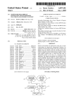
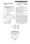
FIG. 1 shows an adjustable RF modulator for a video
ers use continuously adjustable RF modulators instead of
receiver according to the invention.
channel 3/4 switches. The adjustable RF modulators allow
FIG. 2 shows an adjustable RF modulator for a video
an unused television channel in the channel 1-125 band, for
receiver according to the invention involving a remote
example, to be used as the modulator channel. Although the
control unit and a modulator channel display.
satellite receiver may be manufacturer pre-set to a certain
modulator channel, for example channel 65, when delivered
DETAILED DESCRIPTION OF THE DRAWINGS
to the consumer/operator, the operator is able to select any
of the available channels as the modulator channel. The
A satellite video signal receiver modulator stage 12 incor
operator may do this by means of a particular menu selection
porating the principles of the invention is shown in the block
using a remote control device.
55 diagram of FIG. 1. A received video signal, after processing
Operator adjustable modulators may present problems.
by an input processor 14, is modulated onto a carrier
One problem that may arise is incompatibility between a
frequency Fc by modulator 50. Modulator 50 receives the
video receiver (satellite receiver or VCR) modulator output
carrier frequency from a Phase-locked Loop (PLL) network
channel and the channel to which a television receiver,
20 and provides an RF modulated output signal to a televi
receiving the modulator output, is tuned. Such an incom
sion receiver 52. The PLL output carrier frequency Fe is
patibility may occur if the operator is unaware of the
determined by a microprocessor 15 and by a reference
modulator channel setting of the video receiver, and sets the
frequency provided by a source 45. Microprocessor 15
television receiver to a di?erent channel. Then, the televi
selects the channel that is used as the modulator channel by
sion receiver tuner will not be set to the same carrier
frequency as the video receiver RF output signal. This
situation may occur if the operator forgets which modulator
channel he has selected, if he inadvertently changes the
65
controlling the carrier frequency Fe that is output by PLL 20.
Microprocessor 15 selects the modulator channel in
response to inputs received from an operator usable switch
network 10 and an operator menu control and display
5,541,671
3
4
network 16.
The operator may use menu control 16 to select a main
the status of switch network 10. The pushbuttons are
arranged so that they provide, on activation, a change in the
(non-default) channel as the modulator channel only when
the satellite receiver and the television receiver are compat~
microprocessor 15. Alternatively, for example, these signals
ibly tuned to the same modulator channel frequency so that
may be coupled to the microprocessor interrupt inputs. In
this case pushbutton activation interrupts the operation of
logic state of digital signals which are periodically read by
a valid image is displayed by the television receiver, which
microprocessor 15 so that microprocessor 15 does not need
to periodically read switch network 10.
Microprocessor 15 both detects and decodes the sequence
displays the menu. As an alternative to selecting the main
channel as the modulator channel using control 16, the
operator may select a predetermined (manufacturer set)
default channel as the modulator channel using switch
network 10. The operator in using menu control 16 of the
satellite receiver to select the modulator channel sets the
modulator output channel frequency Fe for the satellite
receiver. This new frequency may be a manufacturer pre~set
10
of pushbutton activation. Upon recognizing a prescribed
sequence, microprocessor 15 instructs PLL 20 to output the
default channel carrier frequency to the carrier frequency
input of modulator 50. The default channel setting is stored
in non-volatile memory of microprocessor 15. Preferably,
the default channel is hard-coded in microprocessor 15 by
default channel frequency, or a main non-default channel
frequency.
the manufacturer. PLL 20 is a conventional programmable
operator forgets the channel, if another operator changes the
phase locked loop composed of a phase/frequency detector
30, a compensation and ampli?cation network 35, a voltage
main channel, or if the main channel is “forgotten” by the
controlled oscillator (VCO) 40 and a programmable fre
If a main channel is chosen, a problem may arise if the
system, e.g., in the case of an electrical fault. In order to 20 quency divider 25. A logic control value is written by
microprocessor 15 into a register in programmable divider
recover from these situations, it is desirable to return the
25 to determine the PLL output carrier frequency Fc pro
system to a known modulator channel con?guration. In a
vided by VCO 40 to modulator 50.
?rst recovery mode, this may be done by selecting a manu
facturer pre-set default channel to override the current
modulator channel selection, by means of switch 10, for
example. In a second recovery mode, this may be done by
recalling a previous main channel selection from memory.
25
An operator may use switch network 10 to manually
voltage of detector 30, representing the phase/frequency
select a predetermined (manufacturer set) default modulator
channel without having to scroll option menus (using control
16) displayed by the television receiver. An operator may
also use switch network 10 without having to obtain a valid
television picture display. This is important because both of
these actions may be impossible if there is an incompatibil
ity between the satellite receiver and television receiver
modulator channel settings. This means that the possibility
such an incompatibility caused a television receiver picture
loss cannot be eliminated without operator intervention. The
operator intervenes, under the direction of the operator’s
instruction manual, by selecting the modulator default chan
error, is ampli?ed and compensated by unit 35 to provide an
oscillation frequency control signal to VCO 40. The ampli
?cation and compensation provided by unit 35 ensures the
stability of the PLL. The compensation may be in the form
of ?ltering as known.
Similarly, microprocessor 15 monitors the status of output
signals produced by menu control 16 in response to operator
selection of a modulator main channel. Microprocessor 15
responds to these signals by causing PLL 20 to generate an
output carrier signal Fc at the frequency of the modulator
main channel selected by the operator using menu control
16.
nel using switch network 10 as part of a set-up or fault
diagnosis procedure. The procedure directs the operator to
?rst select a satellite receiver modulator default channel, and
then to select the same channel on the television receiver. By
this procedure the operator restores the receiver equipment
The PLL output frequency is divided by programmable
divider 25 and compared by detector 30 to a frequency
reference from source 45. The division performed by divider
25 is determined by the logic control value written to a
register within divider 25 by microprocessor 15. An output
The VCO 40 output frequency determined by micropro
45
to a known usable state with both the satellite receiver and
television receiver compatibly tuned to the same channel.
Switch network 10 illustratively comprises three multi
cessor 15 is the carrier frequency used by modulator 50.
Modulator 50 frequency modulates this carrier frequency
with the input signal from source 14 containing the video
information to be output by the satellite receiver. The output
signal from modulator 50 is a frequency modulated RF
signal containing the desired video information. This output
function pushbuttons that are mounted on the satellite 50 signal is provided to other units as required, such as a
receiver unit and are accessible to the operator. In order to
television receiver. The carrier frequency of the satellite
restore the satellite receiver to a predetermined modulator
receiver output signal is the default channel frequency
default channel set by the manufacturer, the operator presses
the three pushbuttons of network 10 in a prescribed
sequence. Both this prescribed sequence and the actual
selected by microprocessor 15 via switch network 10, or the
main channel frequency selected via menu control 16.
55
Switch network 10 of FIG. 1 may exhibit a variety of
channel used as the default channel may be disclosed to the
con?gurations in addition to multi-function pushbuttons as
operator in the owner’s instruction manual, or by printed
discussed. For example, network 10 may use a single
instruction on the satellite receiver unit itself. More than one
dedicated switch with several ?xed positions. One of these
default channel may be available for selection using differ
positions may select a manufacturer set default channel as an
ent pushbutton sequences. This improves the likelihood that 60 alternative to a modulator main channel selected from a
the operator can select a default channel that is unused in his
displayed menu using control 16. A second position, in a
local broadcast area. The operator may prefer to manually
recovery mode, may cause the satellite receiver to revert to
select the modulator default channel using switch network
a main channel previously selected by the operator using the
10 if selecting the modulator channel from a displayed menu
selection menus. In another recovery mode, a third position
obtained by using control 16 is more complicated.
Pushbutton activation of the switches in network 10 is
detected by microprocessor 15, which periodically monitors
65
may cause the satellite receiver to automatically select a
manufacturer pre-set default channel. Other switch positions
may provide additional manufacture set default channels.
5,541,671
5
6
This result would also be useful when the operator has
forgotten the previously set modulator main channel. In this
bands in accordance with the requirements of a particular
system. Also, the disclosed modulator output channel selec
case the default channel provided would be known to the
operator from the instruction manual, or it may be displayed,
tion system may be used in a VCR as well as in a satellite
receiver.
What is claimed is:
1. A video signal receiver for modulating a carrier with
received input information to provide a modulated output
for example, by means of a display panel 70 shown in FIG.
2.
Another embodiment of the invention is shown in FIG. 2.
In FIG. 2 the default channel selection and the main channel
selection are both accomplished using a remote control unit
60. In FIG. 1 in contrast, a manufacturer pre-set default
signal compatible with a television signal receiver, said
video receiver including apparatus comprising:
means for generating channel carriers at carrier frequen
cies within a band of television channel frequencies,
and having a control input and an output for providing
channel is selected using switch network 10, and modulator
main channels are selected by the operator using menu
display control 16. The system of FIG. 2 includes viewer
a generated channel carrier in response to a control
operated infra-red remote control unit 60, a receiver infra
red remote control interface network 65 and a representation 15
of a satellite receiver display panel 70 which are not present
in the system of FIG. 1. Other elements in FIG. 2 correspond
to similarly labeled elements in FIG. 1. Units 60 and 65 are
of conventional infra-red type design but could also be a
different design type such as units that operate at radio
signal to said control input of said generating means for
able channel carrier as an alternative to said channel
25
provide said modulated output signal; wherein:
means is a channel carrier other than said manufacturer
preselected available channel carrier; and
microprocessor 15 programs PLL 20 to output the selected
channel carrier frequency. This is performed in the manner
described in connection with the embodiment of FIG. 1.
Finally, also as described in connection with FIG. 1, modu
lator 50 frequency modulates the selected channel carrier
said second means selects said channel carrier from a
plurality of ?xed, manufacturer preselected channel
carriers.
2. A video signal receiver for modulating a carrier with
received input information to provide a modulated output
frequency with the video information of the input signal.
signal compatible with a television signal receiver, said
video receiver including apparatus comprising:
40
ever, other types of display devices may also be used, such
as Liquid Crystal Displays (LCDs). The operator, on view
ing the display, can immediately determine if there is an
incompatibility between the satellite receiver modulator
output channel frequency and the channel to which an
associated television receiver is tuned. If an incompatibility
a generated channel carrier in response to a control
?rst user operated means providing a ?rst control signal to
said control input of said generating means for manu
45
signal to said control input of said generating means for
manually selecting a manufacturer preselected avail
able channel carrier as an alternative to said charmel
50
carrier selected by said ?rst means; wherein
said channel carrier selected by said ?rst user operated
means is a channel carrier other than said manufacturer
preselected available channel carrier;
55
the operator carmot visually determine that there is an
means, having an input coupled to said output of said
generating means, for modulating a generated carrier
selected by said ?rst means or a carrier selected by said
second means with said received input information to
incompatibility between the satellite receiver and television
tuner channels. This means, that operator intervention is
required to determine whether such an incompatibility exists
and is responsible for picture loss on the television receiver.
The operator intervenes by selecting the modulator default
channel, using remote control 60, under the instruction of
the user’s manual.
In the disclosed system, both main channel and default
channel modulator frequencies are selected from the UHF
broadcast television band to facilitate channel tuning. In
other systems, channel selections may be from different
ally selecting a generated channel carrier;
second user operated means providing a second control
exists, the operator can use remote unit 60 to select a default
channel or a main channel as the modulator channel.
If display 70 is not provided in the FIG. 2 embodiment,
means for generating channel carriers at carrier frequen
cies within a band of television channel frequencies,
and having a control input and an output for providing
signal applied to said control input;
played by satellite receiver display panel 70. This visual
indication may be a standard Light Emitting Diode (LED)
carrier selected by said ?rst means; and
means, having an input coupled to said output of said
generating means, for modulating a generated carrier
selected by said ?rst means or a carrier selected by said
second means with said received input information to
said channel carrier selected by said ?rst user operated
microprocessor 15. Upon receipt of this command signal,
type of display and is driven by microprocessor 15. How
ally selecting a generated channel carrier;
manually selecting a manufacturer preselected avail
In the embodiment of FIG. 2 the operator selects a main
channel or a manufacturer pre-set default channel by, for
Additional pushbuttons or sequences thereof may provide
?rst and second recovery modes respectively automatically
engaging a manufacturer default channel, or recalling from
memory a previously selected modulator main charmel, as
discussed in connection with FIG. 1.
The number of the channel selected by microprocessor 15
as the satellite receiver output modulator channel is dis
?rst user operated means providing a ?rst control signal to
said control input of said generating means for manu
second user operated means providing a second control
frequency, for example.
example, pressing a designated pushbutton or a sequence of
pushbuttons on remote control unit 60. A resulting infra-red
output signal from unit 60 is transmitted to infra-red receiver
interface network 65. Network 65 decodes the infra-red
signal and provides a resultant decoded command signal to
signal applied to said control input;
provide said modulated output signal;
60
means for automatically replacing a channel carrier
selected by said ?rst means with said manufacturer
preselected channel carrier; and
means for automatically re-establishing a channel carrier
65
previously selected by said ?rst means by recalling said
previously selected channel carrier from memory.
3. A video signal receiver for modulating a carrier with
received input information to provide a modulated output
5,541,671
7
8
signal compatible with a television signal receiver, said
video receiver including apparatus comprising:
second user operated means providing a second control
signal to said control input of said generating means for
manually selecting a manufacturer preselected avail
means for generating channel carriers at carrier frequen
cies within a band of television channel frequencies,
and having a control input and an output for providing
able channel carrier as an alternative to said channel
carrier selected by said ?rst means;
means, having an input coupled to said output of said
generating means, for modulating a generated carrier
selected by said ?rst means or a carrier selected by said
second means with said received input information to
a generated channel carrier in response to a control
signal applied to said control input;
?rst user operated means providing a ?rst control signal to
said control input of said generating means for manu
provide said modulated output signal; wherein
ally selecting a generated channel carrier;
said channel carrier selected by said ?rst user operated
second user operated means providing a second control
means is a channel carrier other than said manufacturer
signal to said control input of said generating means for
manually selecting a manufacturer preselected avail
preselected available channel carrier; and
means for automatically re-establishing a channel carrier
able channel carrier as an alternative to said channel
previously selected by said ?rst means by recalling said
previously selected channel carrier from memory.
5. A video signal receiver for modulating a carrier with
received input information to provide a modulated output
signal compatible with a television signal receiver, said
carrier selected by said ?rst means wherein
said channel carrier selected by said ?rst user operated
means is a channel carrier other than said manufacturer
preselected available channel carrier; and
means, having an input coupled to said output of said
generating means, for modulating a generated carrier
20
selected by said ?rst means or a carrier selected by said
second means with said received input information to
provide said modulated output signal; wherein
said second means further includes
multi-function 25
switches; and
said multi-function switches require sequential activation
for selecting said manufacturer preselected channel
carrier by said second means.
4. A video signal receiver for modulating a carrier with
received input information to provide a modulated output
signal compatible with a television signal receiver, said
video receiver including apparatus comprising:
means for generating channel carriers at carrier frequen
35
cies within a band of television channel frequencies,
and having a control input and an output for providing
a generated channel carrier in response to a control
signal applied to said control input;
?rst user operated means providing a ?rst control signal to
said control input of said generating means for manu
ally selecting a generated channel carrier;
video receiver including apparatus comprising:
means for generating channel carriers at carrier frequen
cies within a band of television channel frequencies,
and having a control input and an output for providing
an output channel carrier in response to a control signal
applied to said control input;
a user operated selection network providing a ?rst control
signal to said control input of said generating means for
manually selecting an output channel carrier with a
frequency other than a manufacturer preselected chan
nel carrier frequency;
user operated means for automatically re-establishing a
channel carrier previously selected by said user oper
ated selection network by recalling said previously
selected channel carrier from memory and providing a
second control signal to said control input of said
generating means to select said output channel carrier;
and
means for modulating said output channel carrier with
said received input information to provide said modu
lated output signal.