1
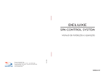
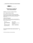
Commander / PC Admiral
Electronic Bingo Systems
O
75
Operator’s Manual
Arrow International
Equipment Division
2
0
G
O
B
I
N
I
O
G
N
I
B
7
O
66
B
Thank you for choosing to purchase Arrow International’s Capitol Bingo
Equipment. We are confident that you will be completely satisfied with
our high quality, durable bingo equipment. Our Capitol Bingo Equipment
has the most technologically-advanced electronics and is designed for
easy and reliable operation and trouble-free maintenance by the operator.
We are proud to announce that we have been given design and
safety certification approval on all our bingo equipment from
Underwriter’s Laboratories, Inc. (UL). Arrow International, Inc. is
the only bingo equipment manufacturer that has earned the UL
approval certification. Look for the UL seal of approval on all our
Capitol Bingo Equipment.
Arrow manufactures the highest furniture quality, hand crafted equipment consoles in the industry. Our metal fabricated steel consoles are
constructed of the finest, heavy duty materials available and guaranteed
to withstand many years of use.
This equipment manual introduces you to the Commander and PC
Admiral electronic bingo systems. It will take you step by step through
unpacking your flashboard and the simple procedures for installation, set
up and operation. Easy to follow instructions and illustrations allow you
to perform routine service and maintenance.
Arrow’s hard work and dedication enable us to offer you a breadth of
product line that continues to grow. We are proud to offer you the most
extensive charitable fundraising product line consisting of high quality,
easy to open Popp-Opens™ tabs; “Top Shelf” banded jar tickets; the
largest series of bingo paper available in the largest variety of colors,
patterns and cuts to meet your game’s needs; Tear Opens™; and our
popular Wink® Ink, Ink-A-Dot™ and Electra Dot™ bingo markers. This
dedication to providing an extensive line of high quality products is
accompanied by our commitment to satisfying your product needs with
fast and trouble free service.
We value you as a customer and always welcome and appreciate your
comments and suggestions to help improve our products. Our best
suggestions always come from our game operators and distributors. We
want you to always be a satisfied customer, and we will continue to
design and improve our products through the valuable feedback received
from you and our reliable network of Arrow Distributors.
Once again, thank you for choosing Arrow International/Capitol for your
charitable fundraising needs.
John E. Gallagher, Sr.
President
ARROW
CAPITAL GAME
REVISION 4-2-92
2
Commander / PC Admiral Electronic Bingo Systems Manual
Table of Contents
I.
Unpacking .................................................................................................
A. Console ..........................................................................................
B. Flashboard .....................................................................................
Warranty Assurance ...........................................................................
II.
Computer Installation .............................................................................. 6
A. Computer Cabling Set Up ........................................................... 6
III.
Flashboard Installation ............................................................................ 7
A. Suggested Number of Flashboard Mount Assemblies .......... 7
B. Wall Mounting Preparation for Flashboards ........................... 7
C. Wall Mounting Instructions ....................................................... 8
D. Ceiling Mounted Flashboards (optional) ................................. 9
Ball Quality Assurance ..................................................................... 11
IV.
Console Controls ....................................................................................
A. Commander and PC Admiral console blower controls .......
B. Other Controls ............................................................................
C. Ball Tray Select Switch—PC Admiral only ............................
V.
Operation ................................................................................................. 12
VI. Periodic Customer Servicing .................................................................
A. Cleaning your Bingo System ....................................................
B. Changing Console Light Bulbs ................................................
C. Changing Flashboard Light Bulbs ..........................................
D. Changing Flashboard Fuses .....................................................
4
4
4
5
11
11
11
11
14
14
15
16
17
VII. Troubleshooting ..................................................................................... 18
VIII. Electrical Specifications ..........................................................................
A. Commander console ..................................................................
Blower Fuse ................................................................................
B. PC Admiral console ...................................................................
Blower Fuse .................................................................................
C. 4" Flashboard - Numbers, Game Indicator and DV ..............
25
25
25
25
25
25
IX. Wiring Diagrams .................................................................................... 26
A. Commander Wiring Diagram .................................................. 26
B. PC Admiral Wiring Diagram ................................................... 26
D. 4" Flashboard Primary Wiring Schematics - Numbers, Game
indicator & Dollar Value ........................................................... 27
E. Bridge Rectifier ........................................................................... 28
F. ACRC Darlington Map ............................................................ 29
G. ACRC Darlington Map Detail .................................................. 29
Capitol Bingo Equipment Limited Warranty .............................................. 31
Damage Action Process
Your Capitol Bingo Equipment
contains delicate electronic equipment. It is imperative that you
thoroughly inspect the contents of
the package before accepting from
the carrier. In case of damage, make
a note on the bill of lading before
accepting, take a photo of the
damage, and keep the packaging to
aid in recovering the amount of
claim against the carrier.
In case of severe damage, refuse the
equipment from the carrier.
If the product is damaged but
acceptable, take a photo before and
after unpacking as a record of the
damage and contact the carrier’s
agent immediately for inspection.
Be sure to obtain a copy of the
inspection report for your records.
If these precautions are not taken,
we cannot assist you in recovering
the amount of the claim against the
carrier.
Commander / PC Admiral Electronic Bingo Systems Manual
3
I. Unpacking
G
O
B
I
N
CUT AND REMOVE SHEET
PLASTIC FROM CONSOLE
O
G
N
I
B
COMPUTER UNPACKING
A. Console
The Commander and PC Admiral are shipped via common carrier.
Each system is wrapped in sheet plastic. Cut the wrapping and
discard. Inspect your console for any signs of shipping damage.
Immediately report any defects or shipping damage to your equipment distributor.
MONITOR UNPACKING
The computer components and optional video and sound equipment
are shipped separately. Before opening any of these packages, inspect
each for external damage. Again, report any visible damage to your
equipment distributor.
Open the box holding the computer. Remove the top packing insert
and keyboard from the box. Next, grasp the computer cabinet firmly
under both ends, lift straight up and place on a secure table. Save the
cartons and packing in case you need to move or ship the computer at
a later time. The power cord will be on the bottom of the computer.
Carefully remove all staples on the box holding the monitor. Slide the
monitor out from the box. The power cord will be in the back. The
DOS manuals and disk set can be found on top of the computer.
SAMSON BALLS
Parts Included
O
G
B
5
12
75
G
32
50
I
22
B
13
0
70
B
B
13
I
7
O
66
N
G
N
31
59
39
B
10
20
0
41
47
28
70
N
N
G
N
O
66
39
G
59
I
G
55
Note: If severe damage to the carton
or flashboard is discovered, a
photograph will provide an excellent record and may assist in
processing claims against the
carrier.
4
Commander
Admiral
1
1
1
1
1
1
1
1
1
1
2
1
1
1
Computer
Keyboard
Monitor
Samson Balls
Computer manual
w/disk set
Bingo Programming Manual
B. Flashboard
Your fhboard is banded into a heavy cardboard enclosure with foam
inserts at each end and in the middle. This carton is marked with
various warning labels and stampings. Lay the carton down flat,
observing labels indicating which side is up.
Commander / PC Admiral Electronic Bingo Systems Manual
B I N G O
BINGO EQUIPMENT
by
ARROW
B
I
N
G
O
1 2 3 4 5 6 7
16 17 18 19 20 21 22
31 32 33 34 35 36 37
46 47 48 49 50 51 52
61 62 63 64 65 66 67
Before opening, closely inspect the carton
for evidence of shipping damage such as
puncture holes, tears, and crushed edges or
corners. Damage on the carton may alert
you to damage to the flashboard.
Use scissors to cut all straps. Carefully lift
off the carton top. Slide the end pieces off
to allow access to the handles. Make sure
the back of the unit is facing down on the
cardboard to prevent scratching. Obtain
assistance in setting the flashboard upright.
8 9 10 11 12 13 14 15
23 24 25 26 27 28 29 30
38 39 40 41 42 43 44 45
53 54 55 56 57 58 59 60
68 69 70 71 72 73 74 75
LAST NUMBER CALLED
$
DOLLAR VALUE
CARDBOARD BOX
FOAM INSERTS
B
I
N
G
O
CARDBOARD BOX
FOAM INSERTS
Caution: This flashboard weighs approximately 185 pounds, get assistance
before lifting.
Do not destroy or discard carton materials until after final inspection
and testing. Inspect the flashboard to insure that all plexiglass is in
place and free of cracks or heavy scratches. Inspect the masonite
panels for damage. I f damage to your equipment is evident, or if you
have problems in any of the above areas, contact your area distributor
immediately for assistance.
Warranty Assurance
At this time, please verify the serial numbers and fill out the warranty
cards. On the flashboard, the serial numbers are located on the left
side below the handle. On the Commander and PC Admiral console,
they are located on the operator’s left side near the flashboard connectors.
To validate your warranty, complete all requesteed information
and return the completed card to
Arrow International.
A second warranty card appears on the back cover of this manual. We
suggest that you fill out this card and keep the information on hand
for future reference.
Commander / PC Admiral Electronic Bingo Systems Manual
5
II. Computer Installation
1.
Place the computer on the top slide out drawer in the right
compartment of the console. Place the printer underneath the
computer on the slide out drawer in the right compartment of the
console.
2.
Place the monitor near the 1" hole on the top right side of the
console. If you have a Commander, place the keyboard on the
slide out drawer on the inside right of the console.
FLASHBOARD DATA CONNECTIONS
EXTRUDED
FLASHBOARD
SIDE PANEL
UPPER LEFT SIDE
METAL
FABRICATED
FLASHBOARD
SIDE PANEL
POWER SWITCH
A. Computer Cabling Set Up
OUTPUT
TURN POWER OFF BEFORE
CHANGING LIGHT BULBS
1.
ON
2.
OFF
ARROW INTERNATIONAL
and our subsidiaries Capitol Game Mfg./Metro Game Mfg.
MODEL: GAME PATTERN INDICATOR
PART NO. 00000
SERIAL NO. 0000000 DATE OF MFG: 1-3-92
120VAC 12 AMP
SUITABLE FOR
INDOOR USE ONLY
MADE IN USA
UL
®
LISTED 6L26
AMUSEMENT AND
GAMING MACHINES
INPUT
The ribbon cable with the large D-shaped connector (DB-25) plugs
into the back of the computer labeled “Switch Bar.”
The coiled cable with cylindrical connector plugs into the back of
the computer labeled “Keyboard.” Keep the notch on the plug
facing up.
INPUT
3.
OUTPUT
INPUT
4.
The telephone cable labeled “Tear” plugs into the lower telephone
jack on the back of the computer labeled as such.
5.
The power cord plugs in on the bottom left side in the back of the
computer, then into the outlet strip to the left of the drawer.
6.
If printer is used, plug it into the large D-shaped connector in the
back of the computer labeled “Par” and tighten the two knurl nuts
to secure.
7.
Connect the small male D-shaped 9 pin monitor connector into
the matching female connector in the back right corner of the
computer and tighten the two screws.
8.
Connect the coax cable from the camera (if used) with the RCA
plug into the top RCA on the back of the computer labeled "Video
In."
INPUT OUTPUT
OUTPUT
INPUT
G
55
VIDEO CAMERA
CAUTIO
RISK OF
ELECT
DO NOT
The telephone cable (RJ-12 connector) labeled “Std”
plugs into the upper telephone jack on the back of
the computer labeled the same.
N
RIC SHOC
OPEN
RISQUE ATTE
K
NTIO
NE DE
PASCHOC
ELECT N
OUVRIR
RIQUE
POWE
R
OFF
TARG
ET
ON
FOCU
S
BEAM
VIDEO
OUT
VIDEO MONITOR
(BACK PANEL)
CONNECTIONS LEADING
TO INPUT/OUTPUT PANEL
(SEE PAGE 5)
IMPEDENCE
DC RESTORATION
VIDEO
OFF
HIGH 75 Ω
6
IN
V-LIN V-HEIGHT
ON
OUT
Commander / PC Admiral Electronic Bingo Systems Manual
PRINTER CABLE
9.
Connect the coax cable with the RCA plug into the bottom RCA in
the back of the computer labeled "Video Out." ( the coax cable will
connect with the RCA plug in the middle when installing a PC
Admiral system.
10. If using a PC Admiral, connect the RCA plug labeled speaker into
the bottom plug on the back of the computer.
Caution: Do not mount the flashboard from the handles. They are
intended for handling only.
III. Flashboard Installation
A. Suggested Number of Flashboard Mount Assemblies
SUGGESTED NO. OF FLASHBOARD WALL MOUNT ASSEMBLIES
PART NO.
NUMBERS
ONLY
NO. & GAME
INDICATOR
NO., GAME INDICATOR
& DOLLAR VALUE
2" Wall Mount
J Bracket
Eye Bolt
45253
415805
46515
2
2
2
2
2
2
3
3
3
4" Wall Mount
J Bracket
Eye Bolt
45254
415805
46515
3
3
3
3
3
3
4
4
4
8" Wall Mount
Eye Bolt
45256
46515
3
5
4
5
4
6
12" Eye bolt
46515
7
7
8
B. Wall Mounting Preparation for Flashboards
Before attempting to mount any flashboard to the wall, you must first
determine the type of wall construction. For hollow walls, we recommend that the flashboard mounting brackets be fastened directly into
wall studs. For concrete, brick and cinder block construction, the
mounting brackets should be fastened using a bolt and anchor
method (moly bolt). If other methods of wall construction are used,
consider ceiling mounting or consult our service department for
advice.
Your PC Admiral or Commander comes standard with a 4" dollar
value brass anodized extruded flashboard.
1. 4" brass and fabricated style flashboards
Use tubular brackets mounted to either a hollow wall or
masonry (solid concrete or cinder block construction) wall, or
ceiling mount it. Eyebolts are available upon request.
Caution: Before attempting any
installation, have a qualified,
licensed and bonded rigger or
electrician verify the type of
installation. Mounting the 8" and
12" jumbo flashboards requires
trained personnel. In many cases,
the local building inspector may
require a permit as well as an
inspection of the site for structural
stability.
Other options:
2. 2" brass style flashboards
Use J-brackets or tubular brackets mounted to either hollow
wall or masonry (solid concrete or cinder block construction)
Commander / PC Admiral Electronic Bingo Systems Manual
7
wall, or ceiling mount it.
3. 8" brass style flashboards
Use ceiling mount or tubular bracket fastened to masonry
wall. (Cannot be fastened to hollow wall.)
13/8"
1 3/8"
4. 12" brass style flashboards
Use ceiling mount only.
C. Wall Mounting Instructions
For hollow wall construction, use 3/8" x 3-1/2" lag bolts. Fasten
brackets directly into wall studs. For masonry construction, use 3/8" x
1-1/2" or larger lag screw expansion shield with suitable length lag
screw.
1. Wall Mount J bracket
(2" aluminum extruded flashboard)
WALL MOUNT
J BRACKET
Supplied with the flashboard are four J shaped wall brackets.
Each bracket has four holes for 3/8" bolts. Choose the height
you feel is desirable for easy viewing and mark the location
on the wall. Then measure in 8-1/2" and 9-7/8" from each end
of the flashboard and mark the vertical center lines. Next,
from the top of the flashboard, measure up 2" and 3-3/8" from
the horizontal center lines.
4 1/"16
1
4 /2"
WALL
MOUNT
TUBULAR
BRACKET
Before drilling any holes, check for possible items behind
holes and make sure that it’s level from side to side. Next,
space any additional brackets equally between the previous
brackets and locate mounting holes, again checking for level.
Drill the proper clearance holes for the method of mounting
appropriate for your wall as described above.
2. Wall Mount Tubular bracket (optional)
(2" and 4" aluminum extruded flashboard and fabricated
flashboard with tubular mounting brackets)
Choose the proper height for easy viewing and mark the
location on the wall. This mounting bracket supports the
flashboard from the bottom and may be used to mark the
mounting holes. Make sure the brackets are level and away
from any obstructions. Equally space the brackets insuring
that all supporting surfaces are level. Drill the proper clearance holes for the mounting method appropriate for your wall
as described above.
3. Wall mounting brackets for 8" style flashboards (optional)
The 8" style flashboards can be mounted to a wall only if the
wall is constructed of brick or cinder block. These flashboards
are too heavy to be mounted on a wood partitioned wall. In
this case, the flashboard must be hung from the ceiling with
eyebolts.
8
Commander / PC Admiral Electronic Bingo Systems Manual
Use 3/8" or larger lag screw expansion shields with a suitable
length lag screw. Use two 8" wall brackets for each flashboard
section. Center the wall brackets evenly to insure even distribution of weight.
EYEBOLT FOR
CHAIN MOUNT
D. Ceiling Mounted Flashboards (optional)
In any ceiling application, the chain or cable must be attached to the
steel building frame or girder. In addition, check with the local
building inspector for local codes governing weight restrictions and
mounting methods.
There are two different methods for suspending these flashboards
from the ceiling.
1. Chain
Use a high quality 3/8" larger chain link made of high
strength alloy, steel grade 80 or its equivalent. Bolt chain
together with a 3/8" x 1-3/4" bolt with two flatwashers,
a lockwasher and a hex nut.
B
I
N
G
O
2. Cable
Use a high quality 1/8" or larger diameter high strength steel
aircraft cable or its equivalent with appropriate cable clamp.
FLASHBOARDS
EYEBOLT LOCATIONS--MEASURED FROM LEFT END
* Measured from the left side of the second half of the flashboard
12" Dollar Value
34 3/4"
64 1/2"
94 1/4"
124 1/2"
*22 3/8"
*67 "
*109 1/2" *143 1/8"
12" Game Indicator
34 3/4"
64 1/2"
94 1/4"
124 1/2"
*22 3/8"
*67 "
*96 3/4"
12" Numbers Only
21"
65 5/8"
110 1/4"
*22 3/8"
*67 "
*96 3/4"
8" Dollar Value
21 3/4"
47 1/2"
86 5/8"
*9 5/8"
*48 3/4"
*97 3/4"
8" Game Indicator
21 3/4"
47 1/2"
86 5/8"
*9 5/8"
*68 1/4"
8" Numbers Only
23 5/8"
43 1/8"
82 1/4"
*9 5/8"
*68 1/4"
4" Dollar Value
22"
46"
94"
118"
3
1
4" Game Indicator
22"
38 /4"
55 /2"
4" Numbers Only
17"
49"
76"
2" Dollar Value
18"
36"
48"
2" Game Indicator
18"
47"
2" Numbers Only
12"
44"
72 1/4"
Commander / PC Admiral Electronic Bingo Systems Manual
9
BINGO
BINGO EQUIPMENT
by
ARROW
B
I
N
G
O
1 2 3 4 5 6 7
16 17 18 19 20 21 22
31 32 33 34 35 36 37
46 47 48 49 50 51 52
61 62 63 64 65 66 67
15
8 9 10 11 12 13 14
30
29
28
27
26
23 24 25
ED
LAST NUMBER CALL
45 $
44
43
42
41
40
39
38
53 54 55 56 57 58 59 60
68 69 70 71 72 73 74 75 DOLLAR VALUE
E. Flashboard Satnd (optional)
A flashboard stand allows for easy mobility and storage of
your flashboard. These stands fit 2" and 4" flashboards and
may be ordered through your distributor.
F.
Input/Output Panel Connections
1.
The input/output panel is located in the left hand compartment
against the left side. Feed all flashboard cables up through the
oval hole in front of the panel.
2.
There are three female panel connectors for regular game
flashboards; two are three pin jones and one is a RJ-12. Plug into
appropriate socket; use adapter cable if necessary. The sockets are
on top and are labeled “BINGO.”
3.
There are three outlets for the tear-open flashboards
in the lower row labeled “TEAR OPEN.” Two of the three outlets
are three pin jones and one is a RJ-12. Insert into the appropriate
socket using adapter cable if necessary.
4.
Connect the coax cable with the RCA plug into the bottom RCA
connector in the back of the computer labeled “Video Out.”
5.
If using hall monitors, connect them by
running the coax cable feed with BNC plugs through the oval hole
by the input/output panel. Connect to the BNC jack labeled
“Video Out.”
FLASHBOARD STAND
For more information on video system configuration see application
note #1. (Included with camera and monitors or request from service
dept.)
COMMANDER I/O PANEL
BINGO FLASHBOARD
TEAR OPEN FLASHBOARD
VIDEO OUT
AUDIO OUT
VIDEO OUT
AUDIO OUT
PC ADMIRAL I/O PANEL
FUSES
ARROW
F1
F2
6 Amp
1 Amp
F3
F4
6 Amp
1 Amp
A
FLASHBOARDS
120 VAC
B
10
Commander / PC Admiral Electronic Bingo Systems Manual
HIGH IMPEDENCE
MIC INPUT
Ball Quality Assurance
Open the box of Samson balls. Check each ball for damage and insert
each into its corresponding slot in the console ball tray. If you find a
ball with a flat spot, immerse it in hot water. Usually, the flat area will
pop out. If the ball is damaged, contact your Arrow distributor for a
replacement.
Note: Please note that the
flashboards function only when
running a session and you may get
a few random lights on the
flashboards until you start a session.
IV. Console Controls
A. Commander and PC Admiral console blower controls
1.
2.
3.
Mixer: On/Off control for the ball mixing arm.
Blower: On/Off control for the ball blower motor.
Blower lamp: On/Off control for the blower chamber lamp.
Note: The PC Admiral has two ball
trays; the left one can be used for
Tear-Open and the right one for
regular games. The Commander has
one ball tray so Tear-Opens can be
run with the random number generator if desired.
Note: There are two (2) sets of console blower controls for the PC Admiral.
B. Other Controls
1.
Audio—Controls auxiliary system power in the Commander
console only.
2.
Power—Controls power to the computer system in the PC Admiral.
COMMANDER CONTROL PANEL
C.Ball Tray Select Switch—PC Admiral only
1.
This switch only appears on the PC admiral
OFF
OFF
OFF
OFF
ON
ON
ON
ON
BLOWER
LAMP
AUDIO
MIXER
Capitol Bingo Equipment Division
ARROW
PC ADMIRAL CONTROL PANEL
BLOWER
MIXER
AUDIO
LIGHTS
OFF
OFF
OFF
OFF
ON
ON
ON
ON
LEFT
BLOWER
Arrow International
MIXER
OFF
OFF
ON
ON
RIGHT
BALL TRAY
OFF
ON
LEFT
RIGHT
COMPUTER
Commander / PC Admiral Electronic Bingo Systems Manual
11
and is used to select the left or right ball
tray.
V. Operation
If you have a PC Admiral, turn the top panel power switch to “ON”. If
you have a Commander, turn the “COMPUTER” switch to “ON.” Initially, when you turn on the computer, it will count through its memory to
512K, display the NCR DOS version, and then ask for the date and time.
Following this, the bingo program will automatically begin.
INITIAL PLAY SCREEN
New Game - BLUE
Dollar amount: $100
Game number: 1 of 4
Pattern: REGULAR Format : Random
Game size : 75 Game Name: BLUE
<F1> = Game pacer: 30 seconds.
<F2> = Begin Game
<F4> = Enter Wild Numbers
<F5> = Immediate Message
<F9> = Next Game
<F10> = Cancel session
STANDARD SCREEN
TEST - BLUE
I19
Ball Timer: 24
11:27:09
<F1> = Call A Ball <F5> = Save Tear
<F6> = Securifier
<F3> = Ball List
<F10> = New Game
<F4> = Flashboard
On the initial installation, run the <F7> option—”SET UP BINGO SYSTEM.” This will allow you to customize your system to your hall requirements. Items such as the printer, flashboard type, and verification on last
ball may be selected with this option. Please refer to the enclosed BINGO
PROGRAM USER’S MANUAL for more information. Please note that the
information entered during setup will be permanently saved so this
option need only be used to install the system or to modify the configuration if any system parameters change (for example, new type of flashboard, etc.)
Refer to the THE BINGO PROGRAM USER’S MANUAL for instructions
on programming the system. Once programmed, the sessions, messages
and patterns are stored permanently on the hard disk. A bingo session is
started from the main menu. Choose <F1> to bring up the session menu.
After entering the session name, the screen will display the dollar amount
of the first game, the present game number being played out of the total
number of games in the session, the game pattern, the format, game size,
game name and the six following functions:
<F1> Game Pacer—Select this to change the ball timer. The timer
defaults to 30 seconds.
<F2> Begin Game—Select this for the standard screen to begin the
bingo game.
<F4> Enter Wild Numbers—Select this to enter wild numbers for the
present game.
FLASHBOARD SCREEN
<F5> Immediate Message—Select this to display messages not in
the session program.
TEST - BLUE
100
DOLLAR AMOUNT: $
LAST BALL CALLED:
B
I
N
G
O
1
16
31
46
61
2
17
32
47
62
3
18
33
48
63
4
19
34
49
64
5
20
35
50
65
6
21
36
51
66
7
22
37
52
67
8
23
38
53
68
9
24
39
54
69
10 11 12 13 14 15
25 26 27 28 29 30
40 41 42 43 44 45
55 56 57 58 59 60
70 71 72 73 74 75
<F9> New Game—Select this to increment to the next game in the
session sequence.
BINGO
BALL TIMER:
<F1> = Call a ball
<F2> = Std Screen
<F3> = Ball List
0
11:30:07
<F5> = Save tear
<F6> = Securifier
<F10> = New Game
<F10> Cancel Session—Select this to cancel the session.
There are three game displays to use when running a game. There are the
standard, ball list and flashboard displays. Once again, refer to THE
BINGO PROGRAM USER’S MANUAL for further details.
At either the standard or ball list screen, press <F4> to display the flashboard screen. A display of the grid of the bingo board, the last ball called,
the dollar amount of the current game, and the winning patterns of the
current game will appear.
12
Commander / PC Admiral Electronic Bingo Systems Manual
The following functions can also be displayed:
<F1> Call Ball—When in random mode, the computer will generate
the numbers at random. One number will be generated each
time <F1> is pressed.
<F2> Standard Screen—Will display the large last ball called
display screen.
<F5> Save Tear—Will save the current game and take you to the
new game screen.
VERIFY MENU
<F6> Securifier—Allows you to interrupt a game to check for a valid
bingo, delete a game pattern or change the dollar amount.
<F10> New Game—Allows you to end the current game. It will then
take you to the new game screen where you can end session or
start next game.
Securifier - BLUE
<F1> = View face 45000
<F2> = Delete current pattern
<F7> = Change $ Amount
<F10> = Return
Once at the flashboard screen, turn on the rocker switches for the mixer
and blower motors. Proceed with your game in the normal fashion by
calling a ball using the automatic timer. If you are running a tear-open
game, call your first standard round of balls then depress <F5> Save Tear,
switch to the right tray if using a PC Admiral and start the first regular
game.
Press <F6> to get the securifier screen and the following menu is
given:
<F1> View Face—Enter the free space number to verify a bingo
called.
<F2> Delete Current Pattern—Drop the winning pattern from the
list of winning patterns.
<F7> Change Dollar Amount—Change the winning dollar amount
such as in progressive games.
CARD FACE SCREEN
©1988 Capital BINGO Equipment
B
13
11
10
7
5
I
16
17
21
30
27
N G O
39 50 61
35 53 71
free
45000
56 72
space
40 55 73
36 48 69
<F10> = RETURN
NOT A WINNER
<F10> Return—Return to the flashboard screen.
To verify a bingo called, press <F1>, type the face number and press
“Enter.” The computer will switch the hall monitors from the ball called
mode to display the bingo face (computer screen will also show the bingo
face). The numbers that show up in reverse video are the numbers of the
balls that have been called. If there is a number flashing, it corresponds to
the last ball called. In the lower right hand corner, a message will state “A
Winner,” “Not a Winner” or “No Last Ball.” Press <F10> to return to the
screen you were previously at before changing to the verify mode.
If you had a valid bingo, but are not running a progressive game, depress
<F10> again to return to the flashboard screen. Then hit <F10> again to
progress to the next game. If you had a valid bingo and are running a
progressive game, change the dollar amount if necessary by hitting <F7>
and entering the new amount. Then hit <F3> to progress to the next
Commander / PC Admiral Electronic Bingo Systems Manual
13
pattern.
The screen will now display the name of the next pattern. Press <F10> to
continue the game. If there was not a valid bingo, hit <F10> to get back to
the flashboard screen and to continue the game.
Continue this procedure until the end of the session. Pressing <F10> at the
flashboard screen will take you to the main menu. To resume the TearOpen game between games, when at the new game screen, hit <F3> to
resume Tear-Open. If you are using a PC Admiral, flip the tray switch to
the left and continue playing.
VI. Periodic Customer Servicing
A. Cleaning your Bingo System
Periodic servicing of your Commander and PC Admiral bingo systems should include cleaning, polishing and light bulb replacement.
Caution: Unplug unit before cleaning
or servicing.
Wood Consoles
Use any high quality wood and furniture polish. Apply with a
soft cloth.
Painted Surfaces—Console and Flashboard
Use a mild soap solution or cleanser. Harsh cleansers or
solvents may damage the paint or lettering. Follow with an
automotive style polish.
Glass Surfaces—Console and Flashboard
Use mild soap solution with a clean, soft cloth.
Caution: Oversraying may remove polish from nearby painted or wood
surfaces. The front of the glas is a painted surface.
Bingo Balls
Clean with a mild soap solution such as liquid detergent.
Harsh cleansers or solvents may damage paint or lettering.
Dry balls thoroughly.
Insert towel dried balls into a paper bag with talcum powder.
Agitate ball and shake off excess powder.
Static Treatment
Lightly spray anti-static compound over the foam and inside
the ball blower windows to eliminate static. Perform this
treatment every few months or when the balls begin to stick
together or to the windows. Do not get anti-static compound
14
Commander / PC Admiral Electronic Bingo Systems Manual
on the ball tube.
B. Changing Console Light Bulbs
Blower/Mixer Lamp
1.
Open the blower chamber access door in the center of the
console and slide out the blower tray for easy access to the
lamp.
2.
Remove the plexiglass lamp panel covering the bulb by
turning the two plastic tabs.
3.
Turn the bulb counterclockwise to remove it.
4.
Insert the new bulb and turn clockwise until snug. Do not
over tighten.
5.
Replace the plexiglass cover and resume operation.
7 1/2 S120
VOLT BULB
PLEXIGLASS COVER
Commander / PC Admiral Electronic Bingo Systems Manual
15
C. Changing Flashboard Light Bulbs
1.
Remove the plastic retaining divider between the plexiglass
panels. Once the strip is removed, carefully slide the panel behind
the panel next to it.
2.
Change the bulb.
3.
Carefully slide the plexiglass panel back to its
original position.
4.
Re-insert the plastic divider.
To change bulbs:
1.
Lightly push the bulb while turning
counterclockwise. The socket
is spring loaded and will push
the bulb out.
2.
Remove the bulb from the socket.
3.
Re-insert new bulb by pushing in while
turning clockwise.
Additional bulbs may be purchased from your
Arrow distributor or a local electrical or
electronics supply house. When ordering
replacement bulbs, ask for #1820 28-volt miniature bayonet
light bulbs.
1820
SHO
LIGHT BULB REMOVAL
WAFFLE
SOCKET
#1820 28 VOLT MINIATURE
BAYONET LIGHT BULB
1820
BULB
ALL 4 PANELS
SLIDE TO ALLOW
ACCESS TO
FUSES & BULBS
LIGHT BULB
REPLACEMENT
PINS ON
BULB FIT
INTO
SOCKET
NOTCHES
B
I
N
G
O
SOCKET
NOTCHES
BULB
PINS
16
Commander / PC Admiral Electronic Bingo Systems Manual
D. Changing Flashboard Fuses
When changing fuses in a fuse block the following steps should be
followed:
1.
Determine which fuse is defective by refering to the fuse
block diagram (pages 18 and 19) or with the use of a voltmeter.
2.
Unplug the unit from the wall outlet.
3.
Gain access to the fuse block by sliding the left most plexiglass to
the right, sliding it in front of the next plexiglass panel.
4.
Using a phillips screwdriver, remove the steel mesh covering the
fuse section.
5.
Remove the fuse with a fuse puller or with a small flat blade
screwdriver by carefully prying one end of the fuse up, grasping
the end and removing the fuse.
6.
Replace the bad fuse with a properly rated fuse. Refer to the fuse
illustration.
7.
Reassemble the unit.
8.
Plug the unit into a 120 volt grounded wall outlet.
ALL 4 PANELS
SLIDE TO ALLOW
ACCESS TO
FUSES & BULBS
B
I
N
G
O
Commander / PC Admiral Electronic Bingo Systems Manual
17
VII. Troubleshooting
The troubleshooting section will help you, your distributor or a local
electrician locate electrical problems that may arise with your bingo
system. Several diagrams and schematics have been included in this
manual to help you trace any problems. Questions going beyond the
information shown here should be directed to your area distrib- utor or
directly to Arrow International. Before referring to the table, please check
to see that the following conditions are met:
1.
Check all connections to system. Look for loose connections or
broken wires. Do not attempt to service the control panel in the
flashboard or console. Only trained service personel are qualified
to work in this area.
2.
If flashboard difficulties arise, check all connections to the flashboard. If power is being supplied to a QD flashboard, the vertical
B-O lamps or the highlite lamps for the game number display
should be on. If these lamps are not lit, check the primary power
to the flashboards.
3.
If flashboard primary power is present, run the TEST function at
the console (if applicable). When TEST is selected, all lamps on
each flashboard will be lit. On the newer Capitol flashboards, a
diagnostic self-test is run at power up.
4.
Consult troubleshooting table.
5.
If further difficulties arise, consult the Arrow factory service
center or an authorized distributor.
This troubleshooting table assumes the following conditions:
1.
2.
3.
The system is plugged into a 120 volt grounded wall outlet.
The power switch is turned on.
All balls are in the ball tray.
Troubleshooting Table begins on the next page.
18
Commander / PC Admiral Electronic Bingo Systems Manual
Commander / PC Admiral Electronic Bingo Systems Manual
19
20
Commander / PC Admiral Electronic Bingo Systems Manual
Commander / PC Admiral Electronic Bingo Systems Manual
21
Flashboard Troubleshooting Table —
PROBLEM
• No flashboard power
• Primary fuse defective
22
CAUSE
CORRECTIVE ACTION
• Unit not plugged into outlet
• Plug unit into a 120VAC
grounded wall outlet.
• No voltage at power outlet
• Check outlet with a test lamp
or a voltmeter, reset circuit
breaker, replace defective
fuses, or consult electrician.
• Primary fuse defective
• Replace fuse with a 4Amp Slo
Blo ACG/3AG.
• Power switch off
• Turn switch on (up position).
• Defective power switch
• Replace switch with a 20 Amp
125VAC UL rated switch.
• Defective bridge rectifier
•Test bridge rectifier with
a voltmeter. There should be
a reading of 28VDC between
the + & - terminals of bridge
rectifier. Replace defective
bridge rectifier with (35Amp
800PIV) Arrow part #41940.
• Defective power transformer
• Test transformer with a
voltmeter. 28VAC should be
read across the unmarked
terminals of the bridge
rectifier. If the voltage
varies +/- 20%, replace
transformer.
• Defective fuse
• Replace fuse with a 4Amp slo
blo ACG/3AG style.
• Defective socket in vertical
or horizontal bingo lights
• Disconnect the + lead off
bridge rectifier. Replace fuse and
carefully turn the power on.
If fuse quits opening, examine
lamp sockets for shorted
sockets or crossed wires.
Will read about 22 ohms if good.
Replace the defective light
sockets.
• Defective bridge rectifier
• Remove unmarked terminals
from bridge. Do not let wires
touch. Replace fuse and carefully
turn power on.If fuse quits
opening, turn the power off and
change the bridge rectifier
(35Amp 800PIV).
• Defective power transformer
• Test transformer with a voltmeter. 28 VAC should be read
across the unmarked terminals
of the bridge rectifier. If the
voltage varies +/- 20%, replace
transformer-Arrow part #42720.
Commander / PC Admiral Electronic Bingo Systems Manual
Flashboard Troubleshooting Table —
continuded
PROBLEM
• B-O lamps on with no
response from console
• No response to ball
insertion in tray
CAUSE
CORRECTIVE ACTION
• Defective data cable
• Repair or replace data cable.
Check for loose or dirty
connections and frayed or
broken wires.
• Flashboard printed circuit board
configured incorrectly
• Check W2 jumper setting.
Refer to pg. 20 for proper
setting for applications.
• 1 Amp logic fuse blown
• Replace fuse with a 1Amp
slo blo ACG/3AG style on
ACRC printed circuit board.
Refer to pg. 9 for access details.
• Defective printed circuit board
• Replace ACRC PCB in
flashboard. Refer to pg. 9
for access details.
• Using wrong flashboard for
particular console
• Consult factory.
• Lamp failure
• Turn power off and replace
lamp in FB (use #1820 for 4" or
#1829 for 2" board). refer to pg
9 for access details.
• Lamp socket failure
• Check connections on back
of lamp socket. Use an ohm
meter to check for a shorted
lamp socket. (0 ohms).
Replace defective socket.
If good, meter will read about
22 ohms.
• Defective crimp on ribbon cable
• Check both ends of ribbon
cable, recrimp connection
or replace ribbon cable.
• SCR/Darlington failure
• Refer to map corresponding
to style of PCB ( pgs. 20-22)
Change SCR/Darlington. SCR’s
must be desoldered to be
replaced. To replace a
Darlington, use an IC puller or
small screwdriver to gently
pry the darlington out of the
socket. Use #41947 for
darlington.
• ACRC PCB failure
• Replace ACRC PCB. Refer to
pg. 9 access.
Commander / PC Admiral Electronic Bingo Systems Manual
23
Flashboard Troubleshooting Table —
continuded
PROBLEM
CAUSE
• Lamp stays illuminated
When ball tray is cleared
• Defective SCR/Darlington
• Refer to map corresponding to
style of PCB (pgs. 20-22).
Change SCR/Darlington.
SCR's must be desoldered to
be replaced. To replace a
Darlington, use an IC
puller or small screwdriver
to gently pry the darlington
out of the socket. Use #41947
for darlington.
• Defective ACRC PCB
• Replace ACRC PCB. Refer to
pg. 9 access.
• Loose data cable
• Check both ends of the data
cable for loose connections
or frayed wires. Replace
data cable as necessary.
• Incorrect printed circuit
board configuration
• Refer to pg 20 W2 jumper
settings for corresponding PCB
configuration. Set jumpers
on ACRC PCB for specific
application.
• Defective ACRC PCB
• Replace ACRC PCB. Refer to
pg. 9 for access.
• Dirty plexiglass
• Refer to pg. 8 for
cleaning instructions.
• Defective bridge rectifier
• Test bridge rectifier with a
volymeter. There should be a
reading of 28VDC between the
+ and - terminals of bridge
rectifier. Replace defective
bridge rectifier with (35AMP
800PIV) Arrow part #41940.
• Low line voltage
• Should read above 105VAC.
Consult electrician.
• Defective secondary fuse
• Refer to fuse map on pgs. 18 &
19. Replace with a 3.2 Amp
slo blo 3AGC/3AG fuse.
• Flashboard blinks
or lights flicker
• Lights dim
• Group of 30 lights out
24
CORRECTIVE ACTION
Commander / PC Admiral Electronic Bingo Systems Manual
VIII. Electrical Specifications
A. Commander console
120VAC 5AMP MAX (No load on auxiliary power outlets)
120VAC 12AMP MAX(Full load on auxiliary power outlets)
Maximum auxiliary outlet rating: 6AMP, 720WATTS
Blower Fuse
6AMP Normal Blow
B. PC Admiral console
120VAC 7AMP MAX (No load on auxiliary power outlet)
120VAC 12AMP MAX (Full load on auxiliary power outlet)
Maximum auxiliary outlet rating: 6AMP, 720WATTS
Blower Fuse
6AMP Normal Blow
C. 4" Flashboard - Numbers, Game Indicator and Dollar Value
Total power required: 5.25 AMPS or 630W
Primary fuse rating: 4 AMP slo-blo
Secondary fuse rating: 3.2 Amp slo-blo
Commander / PC Admiral Electronic Bingo Systems Manual
25
IX. Wiring Diagrams
A. Commander Wiring Diagram
J1-1
AUDIO
DUPLEX
OUTLET
BLOWER
BLOWER
SW1
BLACK
J1-3
WHITE
120 VAC
J1-4
BLOWER
MOTOR
GREEN
SUPP.
PA AMP
MIXER
SW2
MIXER
J1-2
MIXER
MOTOR
SUPP.
LAMP
120 VAC
SHEET 1
LAMP
WIRELESS
MIC. RCV.
JUNCTION &
SWITCH BOX
SW3
SUPP.
120 VAC
OUTLET
STRIP
6-POS
FUSED
120 VAC
NCR PC-6
COMPUTER
120 VAC
PANASONIC
KPX-10902
AUDIO
SW4
SUPP.
SGL
WABER
120 VAC
NCR MONITOR
AUDIO
DUPLEX RECEPTICLE
TO SERVICE
OUTLET
NOTES
______
NOTES:
1) SYSTEM BLOWUP
2) HVAC CONN. ONLY
1.
QUICK DISCONNECT
2.
MALE/FEM. CONNECTION
3.
BUTT SPLICE
B. PC Admiral Wiring Diagram
J1-1
LINE H
BLACK
120VAC
F1-6A 3AG
BLOWER
SW1
J1-3
BLOWER
MOTOR
SUPP.
DUPLEX RECEPTICLE
MIXER
SW2
J1-2
J1-4
MIXER
MOTOR
WHITE
SUPP.
F2-6A .5AG
BLOWER
SW3
J2-1
J2-4
J2-3
BLOWER
MOTOR
SUPP.
GREEN
BLOWER
SW4
J2-2
MIXER
MOTOR
SUPP.
LIGHTS
SW5
SGL WABER
OUTLET STRIP
#412060
MIXER LAMPS
SUPP.
NOTES
______
1.
DENOTES QUICK DISCONNECT
2.
DENOTES BUTT SPLICE
3.
DENOTES MALE/FEM. CONNECTION
4. J1,J2 4-PIN MOLEX
26
Commander / PC Admiral Electronic Bingo Systems Manual
C. Flashboard Data Cables
FLASHBOARD DATA CABLE ADAPTER - RJ12 TO JONES PLUG
FLASHBOARD DATA CABLE - JONES STYLE
25 ft.
25 ft.
J1
J2
BLACK
FLAT
WHITE
BLACK
RED
1
NC
3
DATA-PRES
YELLOW 5
BLUE
6
3
3-PIN MALE
CINCH JONES
#40509
3 2 1
3-PIN MALE
CINCH JONES
#40509
GND
GREEN 4
2
RED
3
FLAT
1
DATA-MICRO
3
GREEN
2
2
GND
2
FLAT
NC
FLAT
FLASHBOARD DATA CABLE
MALE RJ-12
CONNECTOR
#40556
DETAIL “A”
GOLD PINS
FACING
RJ-12 TO RJ12
DETAIL “B”
3
WHITE (1)
2
1
ALL PINS 1 TO 1
CORRESPONDENCE
FLAT
D. 4" Flashboard Primary Wiring Schematics - Numbers, Game indicator & Dollar Value
LINE CORD
BLACK
LINE H
SW1
4AMP 3AG
SLO BLO STYLE
F1
BR1 35AMP 800VOLT
GREEN
WHITE
T1
POWER
C D E F GH
TB-1
P1
P1
P2
P2
GREEN
RED
GREEN
RED
1A
2A
5A
6A
1B
2B
5B
6B
P.C.B.
MOV 2
J1-5
J1-3
J1-6
J1-4
BLACK
BLACK
YELLOW
YELLOW
F5
C
F6
D
P1
F7
E
P2
F8
F
T2
POWER
DATA CONNECTORS
P1,P2 ARE RJ-12 DATA CONNECTORS
P3
FUSE LAYOUT
3A 3B
4A 4B
B
+
TB-1 IS A 6 POSITION TERMINAL BLOCK
FUSE
HOLDERS
P1
P2
P1
P2
A
F4
BR2
-
2
F3
MOV 1
4AMP 3AG
SLO BLO STYLE
F2
TRANSFORMERS
AB
+
LINE N
CHASSIS
GROUND
1
FUSES
-
B
NUMBER
SECTION
B BINGO
A
GAME
PATTERN
N=30
A
B
I
N
G
O
B
C
1-3
D
4-9
FLAST BALL
10-15
NOTE: FUSES F3-F8
ARE 3.2AMP 3AG
SLO BLO STYLE
NOTE: "A" IS A TYPICAL
LAMP LAYOUT OF A-F
CALLED
LAST DIGIT
N=21
E
FIRST
4 DIGITS
N=32
N=30
N=30
N=28
J4
J4
Commander / PC Admiral Electronic Bingo Systems Manual
J5
J5
27
E. Bridge Rectifier
28
-
TO PRINTED
CIRCUIT BOARD
+
TO POWER
TRANSFORMER
Commander / PC Admiral Electronic Bingo Systems Manual
TO FUSE BLOCK
TO POWER
TRANSFORMER
U3
4
U3
5
U3
6
U3
1
U3
2
U3
3
U3
0
U2
9
U2
8
A
U
X
O
U2
5
U2
6
U2
7
U2
3
U2
4
U2
2
G
U1
9
U2
0
U2
1
U1
7
U1
8
U1
6
N
U1
3
U1
4
U1
1
U1
2
U1
5
U1
0
U
8
U
9
U
7
U
5
U
6
U
4
U
2
U8
5
U8
6
U8
7
U8
2
U8
3
DOLL
L
U8
4
U7
9
U8
0
U8
1
U7
6
U7
7
U7
8
DOLL
H
U7
3
U7
4
U7
5
U7
0
U7
1
LAST
#
U7
2
U6
7
U6
8
U6
9
GAME
#
U6
5
U6
4
"
U6
6
U6
1
U6
2
U6
3
U5
8
U5
9
U6
0
GP1
U5
6
U5
7
U5
5
U5
3
GP2
U5
4
U5
2
3
4
W2
1
2
PWR
U
3
U
1
I
B
F. ACRC Darlington Map
G. ACRC Darlington Map Detail
LAMP NUMBERS
DRIVER (92068B)
NUMBERS:
LAMP NUMBERS
DRIVER (92068B)
DOLLER VALUE:
SEGMENTS MAP
#'S ONLY
A
B 1-4
B 5-8
B 9-12
B 13-15
U5
U4
U2
U1
10000-B,C,E,G
10000-D,F,A
1000-B,C,E,G
1000-D,F,A
U80
U81
U78
U77
F
B
I 16-19
I 20-23
I 24-27
I 28-30
U11
U10
U8
U7
100-B,C,E,G
100-D,F,A
10-B,C,E,G
10-D,F,A
U86
U87
U84
U83
C
N 31-34
N 35-38
N 39-42
N 43-45
U17
U16
U14
U13
1-B,C,E,G
1-D,F,A
U32
U31
G 46-49
G 50-53
G 54-57
G 58-60
U23
U22
U20
U19
10'S-B,C,E,G
10'S-D,F,A
1'S-B,C,E,G
1'S-D,F,A
O 61-64
O 65-68
O 69-72
O 73-75
U29
U28
U26
U25
NUMBER OF BALLS:
10'S-B,C,E,G
10'S-D,F,A
1'S-B,C,E,G
1'S-D,F,A
U68
U69
U66
U65
U59
U60
U62
U63
U53
U54
U56
B-G LETTERS
O LETTER
U35
U34
G
E
D
1
2
3
4
5
6
7
8
9
10
11 12 13 14 15
GAME PATTERN:
16 17 18 19 20
GP 1-4
GP 5-8
GP 9-12
GP 13-16
GP 17-20
GP 21-24
GP 25
21 22 23 24 25
GAME PATTERN
INDICATOR
FRONT VIEW
JUMPER 1 & 2 FOR COMMANDER
NO JUMPER 1 & 2 FOR PRES.
JUMPER 1 & 2 FOR CONT. SELF TEST
NO JUMPER 3 & 4 FOR SINGLE SELF TEST
LAST NO. CALLED:
REV.
2.0
U74
U75
U72
U71
JUMPER 1 & 2 FOR GAME IND.
NO JUMPER 1 & 2 FOR DOLLAR VALUE
JUMPER 1 & 2 FOR TIME OUT
NO JUMPER 3 & 4 FOR CONT. SELF TEST
REV.
2.3
Commander / PC Admiral Electronic Bingo Systems Manual
29
30
Commander / PC Admiral Electronic Bingo Systems Manual
Capitol Bingo Equipment Limited Warranty
Set out below are the terms of the Limited Warranty made
by Arrow International, Inc. (“Arrow”) in connection with
the sale of the Capitol Bingo Equipment (the “Equipment”).
1. Limited Warranty
Arrow warrants to the original purchaser (“Purchaser”)
that the Equipment will, for a period of one year from the
date of original purchase from an authorized Arrow dealer,
be free from manufacturing defects in material and workmanship. Purchaser represents to Arrow that no employee,
agent, or representative of Arrow (or of an Arrow dealer)
has made any representation or warranty regarding the
Equipment except as set out herein.
THE WARRANTY CARD MUST BE COMPLETED AND RETURNED TO ARROW WITHIN
30 DAYS OF PURCHASE FROM AN AUTHORIZED CAPITOL BINGO EQUIPMENT DISTRIBUTOR FOR THIS LIMITED WARRANTY
TO BE EFFECTIVE. A purchase receipt or other proof
of date of original purchase must be submitted with the
Warranty Card and will be required before warranty service is rendered.
This Limited Warranty applies to normal commercial use
and does not cover damage which occurs in shipment;
failures which are caused by products not supplied by
Arrow, failures which result from accident, misuse, abuse,
neglect, mishandling, misapplication, alteration, set-up
adjustments or modifications. This Limited Warranty does
not cover any damage to the Equipment resulting from
failure to install in strict conformity with both local fire and
building codes and regulations, or if installation does not
comply with the installation instructions provided by
Arrow.
2. Disclaimer of Warranties
Arrow makes no warranties, express or implied (including, without limitation, merchantability, fitness for particular purpose, or against infringement of any patent),
except as expressly provided herein. The express warranties provided herein are in lieu of and exclude all other
warranties, guarantees or representations, express or implied, whether arising by operation of law or otherwise.
3. Limitation of Remedies
If the Equipment supplied does not conform to the Limited
Warranty set out above, Arrow will, at its option, (a) repair
or replace the Equipment, or part thereof, which is defective or (b) refund so much of the purchase price as Purchaser has paid for the defective Equipment, less 1/24th of
the purchase price for each month between the date of the
purchase from an authorized Arrow dealer and the date of
the discovery of the defect, provided that written notice of
the defect and its nature is given to Arrow as soon as
practical after discovery of the defect, but in no event later
than 90 days from the date of the discovery of the defect.
4. Limitation of Liability
The remedy of repair, replacement, or refund of the purchase price is Purchaser’s sole and exclusive remedy and
will satisfy all of Arrow’s liabilities, whether based on
contract, negligence, tort, product liability, strict liability,
or otherwise. IN NO EVENT WILL ARROW BE LIABLE
FOR INCIDENTAL OR CONSEQUENTIAL DAMAGES,
NOR WILL ITS INABILITY IN CONNECTION WITH
ANY EQUIPMENT OR SERVICE SOLD (INCLUDING
NONDELIVERY OR LATE DELIVERY THEREOF) EXCEED THE SALES PRICE OF SUCH EQUIPMENT OR
SERVICE.
Any obligations of Arrow under this Limited Warranty
will be deemed to have been satisfied if anyone other than
an authorized Capitol Bingo Equipment Dealer services
the Equipment.
6. Transfer of Limited Warranty
Purchaser may transfer its rights under this Limited Warranty, subject to the terms and conditions hereof, to a buyer
(“Buyer”) from Purchaser of the Equipment. Thereafter,
the rights under this Limited Warranty are not transferable. For the transfer by Purchaser of the Limited Warranty
to be effective, the following conditions must have occurred no later than the 30th day following the date of
resale to Buyer:
A. Purchaser must have complied with all requirements to
make the Limited Warranty effective as to Purchaser;
B. The Equipment (as an entire unit and as purchased by
Purchaser) must be transferred to Buyer; and
C. Buyer must have submitted a new warranty card together with proof of purchase by Buyer from Purchaser.
Upon an effective transfer of this Limited Warranty, Buyer
will be considered to be “Purchaser” for paragraphs 1 and
4 hereof.
7. Inspection
With respect to any claim that the Equipment is defective,
Arrow will be allowed a reasonable time to inspect the
Equipment, in place. If the Equipment is altered or removed before Arrow has made such inspection or waived
its right to do so, the obligations of Arrow will be deemed
to have been satisfied.
8. Limitation of Actions
Any legal action against Arrow for a default of its obligations under this Limited Warranty must be commenced
within two years from the date the Equipment was sold by
an authorized dealer of the Equipment.
9. How to Obtain Service
If a problem with this Equipment develops during or after
the warranty period, proceed as follows:
A. Refer to your Operator’s Manual and follow the Troubleshooting Table within the “Service Section.”
B. Contact the authorized Capitol Bingo Equipment Distributor from whom you purchased the Equipment.
C. Contact the Capitol Bingo Equipment Service Manager
at the most convenient phone number listed below:
1 (800) 321-0757 outside Ohio, but within the U.S.A.
1 (800) 537-3479 within the state of Ohio
1 (216) 961-3500 within the 216 area code or
outside the continental U.S.A.
1 (216) 281-5250 FAX
SERVICE CALLS WHICH DO NOT INVOLVE DEFECTIVE MATERIALS OR WORKMANSHIP AS DETERMINED
BY ARROW IN ITS SOLE DISCRETION, ARE NOT COVERED. COST OF SUCH SERVICE CALLS ARE THE RESPONSIBILITY OF THE PURCHASER.
Arrow wants you to remain a satisfied customer. If a
problem occurs that cannot be resolved to your satisfaction,
please contact us immediately. Phone one of the numbers
listed above or write to:
Capitol Bingo Equipment Division
c/o National Service Manager
9900 Clinton Rd.
Cleveland, Ohio 44144
5. Warranty Voided
Please be sure to include the name, model number, serial
number, date of original purchase, and the distributor from
whom you purchased the Equipment, as well as any actions
taken to correct the problem.
Commander / PC Admiral Electronic Bingo Systems Manual
31
WARNING:
You must return the
enclosed warranty card
immediately in order to
insure proper warranty
coverage
CUSTOMER WARRANTY CARD
CAPITOL BINGO EQUIPMENT OWNER REGISTRATION CARD
Model No.
Serial No.
PCB No(s).
Distributor Purchased From
Date Purchased
Name of Organization
Phone (
Address
City
State
)
Zip
Chairman
Address
Phone (
State
City
Additional Information (Optional)
Purchase Price
)
Zip
ATTACH PROOF OF PURCHASE DATE
Average Attendance
No. Of Night Games Played
Time Games Played
Average Spending Per Person
ARROW INTERNATIONAL, INC.
and our subsidiaries
CAPITAL GAME MANUFACTURING
METRO GAME MANUFACTURING
9900 Clinton Rd., Cleveland, Ohio 44144
1 (800) 321-0757 outside Ohio, but within the U.S.A.
1 (800) 537-3479 within the state of Ohio
1 (216) 961-3500 within the 216 area code or outside the continental U.S.A.
1 (216) 281-5250 FAX
ARROW
CAPITAL GAME
© 1992 Capitol Bingo Equipment Division of Arrow International, Inc.
Revision 4-2-92
32
Commander / PC Admiral Electronic Bingo Systems Manual