1
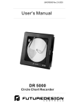
User's Manual
DR 5000
Circle Chart Recorder
Warning Symbol
This
Symbol calls attention to an operating procedure, practice, or
the like, which, if not correctly performed or adhered to, could result
in personal injury or damage to or destruction of part or all of the
product and system. Do NOT proceed beyond a warning symbol
until the indicated conditions are fully understood and met.
Use the Manual
Installers
Read Chapter 1, 2, 3
System
Read All Chapters
NOTE:
It is strongly recommended that a process should incorporate
a LIMIT like Future Design’s L91 which will shut down the
equipment at a preset process condition in order to preclude
possible damage to products or system.
Information in this user's manual is subject to change without
notice.
Copyright May 2003, Future Design Controls, all rights reserved.
No part of this publication may be reproduced, transmitted,
transcribed or stored in a retrieval system, or translated into any
language in any form by any means without the written permission
of Future Design Controls.
UM-DR5000 Rev 1 5-2003
Contents DR5000 Recorder
Chapter 1 Overview
Page Number
1-1 General
1-2 Ordering Code
Chapter 2 Installation
2-1 Unpacking
2-2 Mounting
2-3 Case Location
2-4 Wiring Precautions
2-5 Power Wiring
2-6 Sensor Installation Guidelines
2-7 Thermocouple Input Wiring
2-8 RTD Input Wiring
2-9 Linear DC Input Wiring
2-10 Alarm Relays
2-11 Changing the Chart
2-12 Marking Systems
2-13 Replacement of Pen Ink Style
2-13-1 Replacement of Thermal Head
2-14 Battery Backup
4
5
6
6
7
8
9
10
11
12
12
13
14
14
15
16
17
Chapter 3 Programming
3-1 Recorder Setup
3-1-1 Single Pen Ink
3-1-2 Dual Pen “OEM” Ink
3-1-3 Dual Pen Universal Input Ink
3-1-4 Thermal Recorder
3-2 Alarm Settings
3-2-1 Ink Style
3-2-2 Thermal Style
Chapter 4 Calibration
18
19
20
21
22
22
23
4-1 Pen Zero and Span Ink Style
4-2 Probe Offset Ink Style
4-3 Probe Offset Thermal Style
24
25
26
Chapter 5 Specifications
27
Chapter 6 Defaults/Glossary
Chapter 7 Troubleshooting
Chapter 8 Spare Parts
29
29
31
UM-DR5000 Rev 1 5-2003
Chapter 1 Overview
1-1 General
The DR 5000 is a microprocessor based circle chart recorder.
Programmable alarm options combined with “ease of setup” provide the
flexibility required for multiple recording applications. This manual will
cover both ink type and thermal print versions.
The DR 5000 is the first recorder to “self document” setup configuration
during initial setup and can operate using standard or competitive charts.
The battery backup option (on ink type units) provides up to 48 hours of
recording in the event of power loss, thereby providing an additional
degree of protection for customer processes. A green LED indicates
battery condition, see section 2-14.
The Thermal print version offers a single chart inventory for all recording
needs. “Print your own” chart technology includes real time trend and
digital data directly on the chart.
The unit is powered by 110/220VAC, 50/60Hz. Programmable inputs for
thermocouple types J, K, T, R, B and S as well as 4-20mA or 0-5VDC
are standard. Optional alarm relays are available and programmable for
low, high or band operation. A green LED indicates unit is recording.
A unique setup chart provides the user with an “on the spot” manual.
This setup chart will also self document the current setup for quick
review by an operator.
High accuracy, maximum flexibility, fast response and a simple user
interface are the main benefits of the DR 5000 recorder.
UM-DR5000 Rev 1 5-2003
1-2 DR 5000 Ordering Code
DR 5000
Power Input
1: 110/220VAC 50/60HZ
Selectable
Recording Style
1: 1 Pen Ink
2: 2 Pen Ink
3: 1 Pen Thermal
4: 2 Pen Thermal
5: 2 Pen OEM * (Ink Style)
Outputs
0: None (Standard on OEM style, no relays)
1: 1 Relay, DPDT 1A/240VAC resistive**
2: 2 Relay, DPDT 1A/240VAC resistive**
Display Options
0: None
Chart Option
1: 10” Counterclockwise Rotation
2: 10” Clockwise Rotation
“Counterclockwise ONLY on thermal units”
Enclosure Options
1: Standard (Nema 3)
2: Nema 4X
3: Platen Mount
Special Options
0: None
1: Battery Backup***
Suffix Blank Standard FDC Namestrip
Suffix AA-ZZ Door Namestrip Identifier
*OEM Unit - Pen 1 Universal Input, Pen 2 4/20 ma ONLY, No relays
** Recording style 1 and 2 only allow 1 relay per pen.
*** Ink Recorders ONLY. Allows 48 hours of continuous
recording upon power loss.
UM-DR5000 Rev 1 5-2003
Chapter 2 Installation
Dangerous voltages capable of causing death are sometimes
present when wiring the instrument. Before installation or
beginning any troubleshooting procedures the power to all
equipment must be switched off and isolated. Units suspected of
being at fault must be disconnected and removed to a properly
equipped workshop for testing and repair. Component replacement
and internal adjustments must be made by qualified personnel
only. This recorder operates on 110 or 220 (50-60hz), be sure line
voltage is OFF before connecting recorder.
This symbol represents Earth Ground connection
To minimize the possibility of fire or shock hazards, do not
expose this instrument to rain or excessive moisture.
Do not use this instrument in areas under hazardous
conditions such as excessive shock, vibration, dirt, moisture,
corrosive gases or oil. The ambient temperature of the areas should
not exceed the maximum rating specified in Chapter 5.
2 - 1 Unpacking
Upon receipt of the shipment remove the unit from the carton and
inspect the unit for shipping damage.
If any damage due to transit , report and claim with the carrier.
Write down the model number, serial number, and date code for
future reference when corresponding with our service center. The
serial number (S/N) and date code (D/C) are labeled on the box and
the bottom side of the recorder. Make sure that all items are
accounted for:
1: Battery (for optional battery backup)
2: Ferrite Bead
3: Installation manual
2 - 2 Mounting
Make panel cutout to dimension shown in Figure 2.1.
UM-DR5000 Rev 1 5-2003
Install both mounting clamps and insert the case into panel cutout.
Figure 2.1 Mounting Diagram
2 - 3 Case Location
unpacking, find a suitable location to mount the recorder
* Upon
before wiring power to the unit. After the recorder has been
connected to the main AC power supply, connect the battery
(optional) to the battery strap and place the battery in it’s holder.
Select a location that is well lighted, free from dust, dirt or
corrosive fumes. The instrument should not be located near any
sources of heat or be subject ot sudden or extreme temperature
changes. It should be mounted on a rigid support that is not
subject ot vibration. Refer to figure 2.1 for recorder case
dimensions.
UM-DR5000 Rev 1 5-2003
2 - 4 Wiring Precautions
wiring, verify the label for correct model number and
* Before
options. Switch off the power when checking.
must be taken to ensure that maximum voltage rating
* Care
specified on the label are not exceeded.
*
It is recommended that power of these units to be protected by
fuses or circuit breakers rated at the minimum value possible.
units should be installed inside a suitably grounded metal
* All
enclosure to prevent live parts being accessible from human
hands and metal tools.
wiring must conform to appropriate standards of good practice
* All
and local codes and regulations. Wiring must be suitable for
maximum voltage, current, and temperature rating of the system.
*
control terminals should not be used as jumper points as
* Unused
they may be internally connected, causing damage to the unit.
Take care not to over-tighten the terminal screws.
*
*
Verify that the ratings of the output devices and the inputs as
specified in Chapter 5 are not exceeded.
Electric power in industrial environments contains a certain
amount of noise in the form of transient voltage and spikes. This
electrical noise can enter and adversely affect the operation of
microprocessor-based controls. For this reason we strongly
recommend the use of shielded thermocouple extension wire
which connects the sensor to the unit. This wire is a twisted-pair
construction with foil wrap and drain wire. The drain wire is to be
attached to earth ground at the sensor end only.
UM-DR5000 Rev 1 5-2003
2-5 Power Wiring
T1
L1
T2
T3
T4
L2
AC Input Terminal
AC Input Terminal
The unit is supplied to operate at 110/220VAC 50/60Hz. Check that the
installation voltage corresponds with the power rating indicated on the
product label before connecting power to the unit.
T2
T3
L2
T4
110 VAC Wiring
Earth Ground
Connection
L1
T1
220 VAC Wiring
Earth Ground
Connection
Figure 2.2
Power Supply
The recorder uses AC power when it is operating normally. The battery back-up
option, on ink recorders, will allow the recorder to operate for approximately 48
hours in case of a power loss. AC input can be fused with a 250VAC, .5 Amp fuse.
In order to connect the recorder to the main AC power, you must first gain access to
the microprocessor PC board that is mounted to the back of the chart plate. Your
recorder will have a hinged chart plate held in place by two (2) screws located on
the right hand side of the chart plate. Remove these two screws and open the
hinged chart plate. If you are not sure how to access the back of the chart plate,
please contact FUTURE DESIGN CONTROLS before continuing.
The AC power connections are made to the 4 pin terminal block located on back
side of platen. All AC and ground wires must be a minimum of 16 AWG.
Refer to Figure 2.2 for proper connection to the main AC power.
Earth Ground must be connected at ground lug provided. See Figure 2.2
This equipment is designed for installation in an enclosure which provides
adequate protection against electric shock. Grounding of thisrecorder must meet
national and local codes. Ground wire should be Color coded GREEN or GREEN
with a YELLOW stripe.
Local requirements regarding electrical installation should be rigidly
observed. Consideration should be given to prevent unauthorized persons
access to the power terminals.
UM-DR5000 Rev 1 5-2003
2-6 Sensor Installation
Proper sensor installation can eliminate many problems in a control system.
The probe should be placed so that it can detect any temperature change
with minimal thermal lag. In a process that requires fairly constant heat
output, the probe should be placed close to the heater. In a process where
the heat demand is variable, the probe should be close to the work area.
Some experiments with probe location are often required to find this
optimum position.
Proper sensor type is also a very important factor to obtain precise
measurements. The sensor must have the correct temperature range to
meet the process requirements. In special processes the sensor might
need to have different requirements such as leak-proof, anti-vibration,
Standard thermocouple sensor limits of error are 4 degrees F
( 2 degrees C ) or 0.75% of sensed temperature plus drift caused by
improper protection or an over-temperature occurrence. This error is far
greater than controller error and cannot be corrected at the sensor except
by proper selection and replacement.
In order to connect the probe input device to the recorder, you must first
gain access to the microprocessor PC board that is mounted to the back
of the chart plate.
A ferrite bead has been included to provide additional protection for
electrical “Noise” sensor signal wires can pick up. See drawing below for
correct installation of this device. Figure 2.3
Sensor wire in
Ferrite Bead
Sensor wire out
to Input terminal
Figure 2.3
CAUTION! DO NOT TOUCH the terminals of the transformer
while the recorder is connected to the main AC power supply. To avoid the
risk of possible electric shock, unplug or disconnect the recorder from
the main power supply before attempting to open the recorder. If the
recorder is installed with the battery back-up option, disconnect the 9 Volt
battery to avoid damaging the recorder and draining the battery.
Your recorder will have a hinged chart plate held in place by two (2)
screws located on the right hand side of the chart plate. Remove these
two screws and open the hinged chart plate. If you are not sure how to
access the back of the chart plate, please contact FUTURE DESIGN
CONTROLS before continuing.
UM-DR5000 Rev 1 5-2003
2-7 Thermocouple Input Wiring
Thermocouple input connections are shown in the following figures. The
correct type of thermocouple extension lead-wire or compensating cable
must be used for the entire distance between the unit and the
thermocouple, ensuring that the correct polarity is observed throughout.
Splices in the cable should be avoided, if possible. A Ferrite bead is
supplied with the DR5000 recorder to provide additional isolation against
input noise. Input wiring should be wrapped around the core before wiring
to the recorder inputs. See Figure 2.3
If the length of thermocouple plus the extension wire is too long, it may
affect the temperature measurement. A 400 ohms K type or a 500 ohms J
type thermocouple lead resistance will produce approximately 1 degree C
temperature error .
Figure 2.4 Single Pen Ink Style Inputs
Relay
1
Pen 1
Input
4
UM-DR5000 Rev 1 5-2003
Figur e 2.5 Two Pen OE M
Ink Style
Inputs
Pen 1 Input
Wiring
PEN 1
1
2
3
Wiring
+
PEN 2
Pen 2 Input
MA
4
1
2
4/20 ma
ONLY
Main Board
PEN 1
1
2
3
4
PEN 2
Input Wiring
Pen 1 / Pen 2
F i g . 2 . 6 Two Pe n U n i v e r s a l a n d T h e r m a l Inputs
1
2
3
4
Relay
Relay Connections
PEN 2
Optional
Relay
Optional
Relay Connections
are DPDT Relays
Relay Connections
PEN 1
UM-DR5000 Rev 1 5-2003
2-8 RTD Input Wiring
RTD connections are shown in the previous, with the compensating lead
connected to terminal 4. For two-wire RTD inputs, terminals 2 and 4
should be linked. The three-wire RTD offers the capability of lead
resistance compensation provided that the three leads are of same gauge
and equal length.
Two-wire RTD should be avoided, if possible, for the purpose of accuracy.
A 0.4 ohm lead resistance of a two-wire RTD will produce 1 degree C
temperature error.
2-9 Linear DC Input Wiring Pen 1/Pen 2
DC linear voltage and linear current connections are also shown in the
previous input wiring figures.
2-10 Alarm Relays
If your recorder has the optional relay contacts installed, then
terminal blocks J1 and J2 have been provided for connection to the
relay on the microprocessor PC board of the recorder.
Refer to Figure 2.4 for Single Pen Units.
Refer to Figure 2.6 for Dual Pen Ink and Thermal Units.
NOTE; OEM unit has no Alarm relay outputs.
I
CAUTION! DO NOT TOUCH the terminals of the transformer while
the recorder is connected to the main AC power supply. To avoid the risk
of possible electric shock, unplug or disconnect the recorder from the main
power supply before attempting to access the terminals of the relay. If the
recorder is installed with the battery back-up option, disconnect the 9 Volt
battery to avoid damaging the recorder and draining the battery.
Your recorder will have a hinged chart plate held in place by two (2)
screws located on the right hand side of the chart plate. Remove these
two screws and open the hinged chart plate. If you are not sure how to
access the back of the chart plate, please contact FUTURE DESIGN
CONTROLS before continuing.
The relays are rated for the following maximum Values:
2.0 AMPS at 25VDC
1.0 AMP at 120VAC
Warning: Damage to the recorder may result if the ratings for the relays
are exceeded.
UM-DR5000 Rev 1 5-2003
2-11 Changing the Chart
Press and release the CHANGE CHART key (3 on Figure 2.7). The
pen(s) will move to the left of the chart and green LED will flash rapidly.
Wait until the pen(s) stops above outer ring AND green LED goes to on
steady.
Unscrew the chart "hub" knob at the center of the chart. Remove the old
chart paper and position the new one so that the correct time line
coincides with the time line groove on the chart plate. Refer to Figure 2.10
(Page 17) for the location of the time line groove.
Re-attach the chart "hub" knob and screw securely (by hand) against the
chart. Press and release the CHANGE CHART key (3). The pen(s) will
move to the outer ring, then pause. The green LED will remain on.
Pen(s) will then go to current recording value.
Check to make sure that the pen(s) is marking on the chart paper. If it is
not, then carefully adjust the pen arm to establish contact with the paper.
On a thermal print recorder, the thermal stylus does not need adjustment.
2-12 Marking Systems -”Ink Type Pens”
This type of pen consists of a self contained ink reservoir with a porous
plastic stylus which is snapped around the outer edge of the metal pen
arm.
A pen cap is provided to extend the life of the ink pen during shipping or
when the recorder is not in service. To remove the pen cap, gently lift the
pen arm away from the chart paper. Remove the black plastic pen cap to
expose the fiber tip of the ink pen and gently place the pen back onto the
chart paper. Do not let the pen arm "snap" back onto the chart paper. This
will flatten the fiber tip of the pen and will no longer give you a fine line
marking on the chart paper. Place the pen cap in a safe place for future
use.
If the stylus does not touch the chart, adjustment can be made by slightly
bending the metal pen arm in the center towards the chart paper. Do not
use more pressure than is necessary to create a fine line marking on the
chart paper. Note: As the pen ink supply runs out, the pen color will
become lighter. This indicates that the pen should be replaced.
Figure 2.7
Keypad Layout
UM-DR5000 Rev 1 5-2003
2-12-1 Marking Systems - Thermal
This type of pen consists of a self contained thermal print head that is
attached to a metal “Stylus” pen arm assembly.
Periodic maintenance is not required for this pen type. Since the thermal
print head creates it’s own chart, adjustment for outer ring are made
automatically during each chart change. Replacement of the thermal print
head is covered in 2-13-1. (Pg.16)
2-13 Replacement of Pen “Ink Type”
Recorders that are equipped with fiber tipped cartridge pens are colored
coded RED for pen 1 and BLUE for pen 2.
The pen cartridge is securely fastened to the metal pen arm using a
special "U" clip tab.
For ease of replacement, it is suggested that the two (2) screws that hold
the pen arm be loosened and the pen cartridge and metal pen arm be
removed as an assembly. Refer to Figure 2.10 (page 17) for the location
of the pen arm screws. Unsnap the plastic "U" clip tab of the pen cartridge
from the metal pen arm, remove and discard the old pen cartridge.
Replace the new cartridge by opening the hinge and snapping it securely
around the metal pen arm. Refer to Figure 2.8 for pen cartridge
replacement.
Figure 2.8 Pen Replacement
UM-DR5000 Rev 1 5-2003
2-13-1 Replacement of Thermal Stylus
The thermal print head is securely fastened to the metal stylus arm which
is attached to the pen motor drive assembly.
For ease of replacement, it is suggested that the stylus (with print head
attached) be removed as a complete assembly.
1.) Disconnect AC power from unit.
2.) Remove the two platen screws located on the front of the platen at
the right center of the platen.
3.) Follow the thermal pen leads to the main “mother” board located on
the back of the recorder platen.
4.) Remove the “plug in” thermal print head leads from the main “mother”
board.
5.) Remove the pen arm screws that attach the pen arm stylus to the pen
arm motor assembly located on the front of the platen.
6.) Remove the pen arm assembly.
7.) Install new pen arm assembly in the reverse order of disassembly.
8.) Reconnect AC power to unit. Pen will align itself and begin normal
recording.
Platen - Front View
Platen - Rear View
Stylus Screws
Thermal Print
Head Leads
Thermal Print
Head
Platen Screws
Figure 2.9 Thermal
Recorder Platen Layout
UM-DR5000 Rev 1 5-2003
Mother Board
Thermal Stylus
2-14 Battery Backup “Ink Style” Units
Having the optional 9 volt DC battery back-up in place, will allow the
recorder to continue to function normally for approximately 48 hours in
the event of a power failure.
The green LED assists in indicating battery condition. When a recorder
has this option feature.
If green LED is on continuous, battery voltage is acceptable.
If green LED is flashing rapidly, battery voltage is below 7.5 VDC,
replace battery.
If green LED is not on battery voltage is insufficient and AC power off.
The battery strap and battery holder are located on the front of the chart
plate (refer to Figure 2.10). In order to change the battery, you must
open the recorder case door. Note: Use only NEW 9 volt alkaline
replacement batteries.
Green
LED
Figure 2.10 Recorder Platen
Layout/Battery Installation
UM-DR5000 Rev 1 5-2003
Chapter 3 Programming
3-1-1 Recorder Setup “Single Pen Ink Type”
In order to configure the recorder, you will need the recorder SET-UP
CHART, P/N R18-270 for CCW or P/N R18-272 for CW rotation.
This chart contains the configuration categories of the recorder (Probe
Input, Inner Chart Values, Outer Chart Values, Units, Chart Rotation, Input
Averaging and Relay Options). Place the SET-UP CHART onto the
recorder. This setup chart should be saved for future reference once
setup complete.
1. Place SETUP CHART on recorder (P/N R18-270 for CCW, and
P/N R18-272 for CW)
2. Press and release CHANGE CHART key (3).
3. Wait until pen moves above scale and green LED stops flashing.
4. Press and hold LEFT arrow key (1) until LED goes off, then release
key.
5. Pen will move to outer ring of chart. Wait for LED to flash slowly.
(.8sec on / .8 sec off) LED will continue to flash slowly during setup.
6. Loosen Chart knob and rotate chart to position RED pen in the middle
of the START CIRCLE.
7. Tighten chart knob. Press and release the CHANGE CHART key (3).
Pen will move to PROBE INPUT column on the setup chart.
8. Position pen to the desired selection using LEFT (1) and RIGHT (2)
keys.
9. Press and release CHANGE CHART key (3) to store selection and
advance to next category.
10. Repeat selection process until all categories are selected. You must
Press and release CHANGE CHART key (3) after last category.
11. After all categories are selected, pen will move off scale and LED will
Stop flashing. (Steady on)
12. Remove SETUP CHART and save. Install actual recording chart.
13. Press and release CHANGE CHART key (3).
14. LED will remain on steady, pen will stop at 100% ring, then to alarm
setpoint values (if enabled). LED will turn off when pen(s) reaches
alarm setpoint. Use RIGHT/LEFT arrow keys to adjust alarm value(s)
for pen. LED is on steady when pen(s) are recording actual
values.
Figure 3.1
Keypad Layout
UM-DR5000 Rev 1 5-2003
3-1-2 Setup Of Dual Pen “OEM” Ink Style
In order to configure the recorder, you will need the recorder SET-UP
CHART, P/N R18-270 (CCW) or P/N R18-272 (CW). The second pen
(Blue) on OEM type recorders is fixed for 0/100% of the analog input.
The setup chart contains the configuration categories of the recorder
(Probe Input, Inner Chart Values, Outer Chart Values, Units, Chart
Rotation, Input Averaging and Relay Options). Place the SET-UP CHART
onto the recorder. This setup chart could be left on the recorder behind
the normal recording chart for easy access or behind the platen assembly.
1. Place SETUP CHART on recorder.
2. Press and release CHANGE CHART key (3), pens will begin move off
scale and green LED will flash rapidly. Wait until pens are off scale
AND Green LED goes to on steady.
3. Press and hold LEFT arrow key (1) until green LED turns off. Then
release key. Pens will move to outer ring. Wait for green LED to flash
slowly. (.8sec on/.8sec off) Note; Green LED will continue to flash
slowly during setup mode.
4. Blue Pen will move to outer ring of SETUP CHART first. Then Red
pen will then move to outer ring. Please note: Blue pen will remain at
outer ring of chart during setup. Pen 2 is fixed for 0/100% for analog
input.
5. Loosen chart knob and rotate chart to position Red pen in middle of
the START CIRCLE.
6. Tighten chart knob. Press and release the CHANGE CHART key (3).
Red Pen will move to first selection category to current value.
Position red pen to desired selection using LEFT (1) and RIGHT (2)
keys.
7. Press and release the CHANGE CHART key (3) to store selection.
8. Repeat selection process in EACH category until all categories are
Selected.
9. After last category(Relay) is selected ( this setting should be set to
“
DISABLED”), press and release CHANGE CHART key (3). Pens will
move off scale. Green LED will flash rapidly. Wait until Green LED
goes to on steady. Setup is now complete.
10. Remove and store SETUP CHART. Install actual recording chart to be
used.
11. Press and release CHANGE CHART (3) key. Pens will move to 100%
ring. Then to actual recording values.
UM-DR5000 Rev 1 5-2003
3-1-3 Setup Of Dual Pen (Universal) Ink Style
In order to configure the recorder, you will need the recorder SET-UP
CHART, P/N R18-270 for CCW or P/N R18-272 for CW rotation. Universal
Inputs allow the user to select a different type of input for each pen.
The setup chart contains the configuration categories of the recorder
(Probe Input, Inner Chart Values, Outer Chart Values, Units, Chart
Rotation, Input Averaging and Relay Options). Place the SET-UP CHART
onto the recorder. This setup chart should be saved for future reference
once setup complete.
1. Place SETUP CHART on recorder (P/N R18-270 for CCW or
P/N R18-272 for CW)
2. Press and release CHANGE CHART key (3).
3. Wait until pens moves above scale and green LED stops flashing.
4. Press and hold LEFT arrow key (1) until LED goes off, then release
key.
5. Blue Pen will move to outer ring of SETUP CHART. Red pen will
then move to outer ring. Please note Blue pen setup selections
allowed are categories Input Probe and Relay selections only. Wait
for LED to flash slowly. (.8sec on / .8 sec off) LED will continue to
flash slowly during setup.
6. Loosen Chart knob and rotate chart to position RED pen in the middle
of the START CIRCLE.
7. Tighten chart knob. Press and release the CHANGE CHART key (3).
Pen will move to PROBE INPUT column on the setup chart.
8. Position pen to the desired selection using LEFT (1) and RIGHT (2)
keys.
9. Press and release CHANGE CHART key (3) to store selection and
advance to next category.
10. Repeat selection process until all categories are selected. You must
Press and release CHANGE CHART key (3) after last category.
11. After all categories are selected, pen will move off scale and LED will
Stop flashing. (Steady on)
12. Remove SETUP CHART and save. Install actual recording chart.
13. Press and release CHANGE CHART key (3).
14. LED will remain on steady, pen will stop at 100% ring, then to alarm
setpoint values (if enabled). LED will turn off when pen(s) reaches
alarm setpoint. Use RIGHT/LEFT arrow keys to adjust alarm value(s)
for pen. LED is on steady when pen(s) are recording actual values.
UM-DR5000 Rev 1 5-2003
3-1-4 Setup Of Thermal Recorders.
In order to configure the recorder, you will need the recorder SET-UP
CHART, P/N R18-271. Thermal print recorders use a single thermal
printhead for single and two channel units.
The setup chart contains the configuration categories of the recorder
(Probe Input, Inner Chart Values, Outer Chart Values, Units, Chart
Rotation, Input Averaging and Relay Options). Place the SET-UP CHART
onto the recorder. This setup chart should be saved for future reference
once setup complete.
1.
2.
3.
4.
5.
6.
7.
8.
9.
10.
11.
12.
13.
14.
Place SETUP CHART on recorder (P/N R18-271)
Press and release CHANGE CHART key (3).
Wait until stylus moves to top of chart and green LED stops flashing.
Press and hold LEFT arrow key (1) until LED goes off, then release
key.
Thermal stylus will move to outer ring of setup chart. The left and right
arrow keys can be used to adjust the center line on the print head to
the outer ring of the setup chart at this time. Wait for LED to flash
slowly. (.8sec on / .8 sec off) LED will continue to flash slowly
during setup.
Loosen Chart knob and rotate chart to position the center of the
printhead in the middle of the START CIRCLE.
Tighten chart knob. Press and release the CHANGE CHART key (3).
Pen will move to PROBE INPUT column on the setup chart.
Position pen to the desired selection using LEFT (1) and RIGHT (2)
keys.
Press and release CHANGE CHART key (3) to store selection and
advance to next category.
Repeat selection process until all categories are selected. You must
Press and release CHANGE CHART key (3) after last category.
After all categories are selected, pen will move off scale and LED will
Stop flashing. (Steady on)
Remove SETUP CHART and save. Install actual recording chart.
Recording Chart Part number 00218001.
Press and release CHANGE CHART key (3).
The thermal stylus will now begin printing the chart. The thermal
stylus will print all scales, date/time and trend lines automatically.
UM-DR5000 Rev 1 5-2003
3-2-1 Alarm Settings Ink Style Recorders
Alarm setpoint values are selected by positioning the pen to the actual
value on the recording chart. Alarm settings can be selected or viewed
after CHART CHANGE, recorder setup or during initial power up. To set
the alarm setpoint during normal recording operation, complete the
following steps.
Press and release the CHANGE CHART key ( 3 on Figure 3.2). Wait until
pen(s) moves off scale and LED status changes from flashing to steady.
Press and release the CHANGE CHART (3) again, the pen will begin to
move back onto the chart briefly stopping at (or close to) the outermost
graduation of the chart. Green LED remains on steady during this time.
Single Alarm Setting
After the above operation is complete, the active pen(s) arm will move to
the current alarm setpoint position on the chart (one pen at a time). The
green LED will go out, during this time the alarm setpoint (for each pen)
can be adjusted using the LEFT arrow (1) or the RIGHT arrow (2) keys on
the keypad. Once the alarm setpoint is set, wait for the green LED will turn
on and the pen arm will move to indicate the probe's temperature and the
unit will begin normal recording operation.
Band Alarm Setting
When programming the recorder for band alarm operation, the active
pen(s) will move to the first band setpoint on the chart. The green LED will
go out. The alarm band 1 setpoint can now be adjusted using the LEFT
arrow (1) or the RIGHT arrow (2) keys, once set, wait for the green LED
to turn on. The active pen will then move to the second band alarm
setpoint. The green LED will go out. The alarm band 2 can now be
adjusted. When pen(s) alarm setpoints adjustments are completed, wait
for the green LED to turn on and the pen arm will move to indicate the
probe's temperature and the unit will begin normal recording operation.
The “Change Chart” key is the “RESET” when the recorder is
programmed for latching alarm operation.
NOTE; Alarm reset occurs upon depressing “Change Chart” (3) key
regardless of alarm condition.
Figure 3.2
Keypad Layout
UM-DR5000 Rev 1 5-2003
3-2-2 Alarm Settings Thermal Style Recorders
Thermal alarm relay settings can only be set or reviewed from the
Setup mode.
Install setup chart part number R18-271. Follow the thermal setup
Instructions found in Chapter 3-1-4. (Pg. 21).
Alarm settings are set under Alarm #1 and Alarm # 2 setpoint categories.
The setup procedure must be followed completely to properly store
selected alarm values. Alarms are programmable for hi or low alarm
action as well as latching or non-latching. Latching alarms require a
manual “reset” which is performed by depressing “change chart” key (3).
Note: Alarms will “reset” when pressing the “Change Chart” key
REGARDLESS of the current alarm condition.
Thermal alarms can be programmed as follows:
P1(Hi): Process high alarm (on above setpoint) assigned to Pen1.
P1(Low): Process low alarm (on below setpoint) assigned to Pen 1.
LP1(Hi): Latching high alarm.
LP1(Low): Latching low alarm
P1(Hi/Low): Pen 1 uses both optional relays for alarm.
Alarm 1 is a high alarm. Alarm 2 is a low alarm
LP1(Hi/Low): Pen 1 uses both optional relays for latching alarms.
Alarm 1 is a high latching alarm. Alarm 2 is a low latching alarm.
3-2-1 OEM Style Recorders
No alarm relay options are available on this style recorder.
UM-DR5000 Rev 1 5-2003
Chapter 4 Calibration - Ink Type Only
4-1 Pen Arm Calibration (Zero and Span)
Pen calibration applies to ink type units only and is a two point calibration.
Since Thermal stylus unit print their own outer/inner ring, calibration is not
necessary. To check and/or adjust the recording pen(s) calibration to the
inner and outer graduations of the chart on ink type units, Perform the
following.
1. Remove power to instrument. If unit has battery option also remove
battery.
2. With all power removed, press and hold the CHANGE CHART key (3).
While holding the CHANGE CHART key(3), re-apply power. Release
key upon applying power, either AC or battery which ever is
convenient.
3. The pen(s) will move off scale, LED will flash rapidly. Green LED will
Then go to on steady. If 1 pen ink unit go to step 5 next.
4. The blue pen will then move to 100% ring. Adjust blue pen, if
necessary, using LEFT (1) and RIGHT (2) keys to position pen on
100% ring, then Wait.
5. Red pen will then move to 100% ring. Adjust this pen, if necessary, to
100% ring, using LEFT (1) and RIGHT (2) keys, then wait.
6. Red pen will then move to 0% ring. Adjust pen using LEFT (1)
and RIGHT (2) keys, then wait. Pen will then move full upscale.
If 1 pen unit go to step 8.
7. Blue pen will move to 0% ring. Adjust pen to 0%, using LEFT
(1) and RIGHT (2) keys, then wait. Blue pen will now travel full upscale.
8. Pen(s) calibration is now complete.
Pen(s) will then go directly to actual recording values.
Each time the chart paper or fiber tip pen cartridge is changed, you should
make sure that each pen stops at the inner and outer most temperature
graduation of the chart paper. Otherwise, this pen offset can cause the unit
to record an incorrect temperature on the chart.
Figure 4.1 Keypad
UM-DR5000 Rev 1 5-2003
4-2 Ink Style Probe Offset Adjust
(Pen Offset)
This recorder has been accurately calibrated at the factory. Before making
any adjustments, this instrument should be in service for 24 hours.
Thereafter, if any adjustment is required, perform the following procedure.
1.
Place a Certified Test Thermometer(s) alongside the recorder's sensor
probe(s) in a monitored controlled condition.
2.
Once the temperature has leveled out, compare the position of the
pen on the recorder to the test thermometer's reading, also compare
the Certified Test Thermometer’s reading to the second pen of the
recorder.
3.
If an adjustment is required, for a single pen unit, depress and hold
either the LEFT (1) or RIGHT (2) arrow key. The pen will begin to
move after approximately ten (10) seconds. Using the LEFT arrow (1)
or RIGHT (2) arrow keys, position the pen on the chart to correspond
to the temperature of the Certified Thermometer. Once the corrected
value is obtained no further keystrokes are required.
4.
For two (2) pen ink recorders, you must first select the pen that you
wish to calibrate. This is done by pressing the LEFT (1) arrow key to
select the Red pen or the RIGHT (2) arrow key to select the Blue pen.
The appropriate arrow key must be held down for approximately five
(5) seconds, after which the green LED will go out. Release the key.
The green LED will begin to flash. Adjust the pen to the desired value.
This is done using the LEFT (1) or RIGHT (2) arrow keys. Once the
corrected value is obtained, wait. Green LED will go to on steady
indicating normal recording mode.
Figure 4.2 Keypad
Layout
UM-DR5000 Rev 1 5-2003
4-3 Thermal Style Probe Offset
(Pen Offset)
This recorder has been accurately calibrated at the factory. Before making
any adjustments, this instrument should be in service for 24 hours.
Thereafter, if any adjustment is required, perform the following procedure.
1.
Place a Certified Test Thermometer(s) alongside the recorder's sensor
probe(s) in a monitored controlled condition.
2.
Once the temperature has leveled out, compare the position of the
pen on the recorder to the test thermometer's reading, also compare
the Certified Test Thermometer’s reading to the second pen of the
recorder.
3.
If an adjustment is required, for a single pen unit, depress and hold
either the LEFT (1) or RIGHT (2) arrow key. The printhead will move
to current trend line value. Using the LEFT (1) and RIGHT (2) arrow
keys adjust the center scribe mark on printhead to desired recording
location. Once adjusted wait. Green LED will go to on steady.
Printhead will then resume normal printing operation.
4.
For two (2) pen thermal recorders, you must first select the trend line
that you wish to calibrate. This is done by pressing the LEFT (1) arrow
key to select trend for pen 1 or the RIGHT (2) arrow key to select
trend for pen 2. Hold the selected key until green LED goes out.
Then release the key. The green LED will begin to flash. The
printhead will now move to the current trend line value. Using
LEFT (1) and RIGHT (2) arrow keys adjust the center scribe mark on
printhead to desired recording location. Once adjusted, wait. Green
LED will got to on steady. Printhead will then resume normal
operation.
The remaining pen can now be selected and adjusted, if necessary
Using instructions above.
UM-DR5000 Rev 1 5-2003
Chapter 5
Power
Line Voltage: 110/220VAC, 50/60Hz
Power Consumption: 15 VA maximum
Input
Thermocouple (T/C): Type J, K, T, R, B, S,
RTD: PT 100 ohm RTD (385 curve)
Linear: 4-20 mA, 0-5 VDC
Range: Programmable See Table 5.1
Common Mode Rejection: > 120dB at 60 Hz
Cold Junction Accuracy: ± 0.2ºC@25ºC ambient
Cold Junction Error: ± 0.2ºC@25ºC ambient
Ambient Error: ± 0.01% span/ºC from 25ºC ambient
Isolation: Inputs isolated from outputs
Recording
Chart Size: 10”
Recording Accuracy: ± 0.5% of span (100 division span)
Sensor Break: Full scale Pen < 10 seconds
Chart Speed Ink: Configurable for 4,8,12,24,48,72 or 168 hours
Chart Speed Thermal: Configurable for 12,24,48,72 or 168 hours
Input Filtering: Programmable up to 120 seconds
Options
Relay: DPDT, 1.0 Amps @120 VAC resistive
Relay Program: Process, Band, Non-latching, Latching
Error Protection: De-energized during sensor break
Hysteresis: Set at 2 units, activation is safe sided
Battery Back up:
Ink Style: Up to 48 hours of recording (optional)
Thermal Print Style: Maintains real time clock
Environmental and Physical
Operating Temperature: 0 to 60ºC
Storage Temperature: -40 to 65ºC
Humidity: 0-90% RH (non-condensing)
Agency Approvals: UL / CUL File #E232762, CSA File
Installation Category: ll
Pollution Degree: 2
Altitude: 2000 meters
Vibration: 0.3 to 100Hz @0.2g
Mounting: ± 20 degrees of vertical
± 10 degrees of horizontal
Moldings: Fire retardant Noryl w/acrylic window
Panel Rating : Nema 12X std (Nema 4 optional)
Dimensions: 14.00 (H) x 14.00 (W) x 3.80 (D)
Panel Cutout: Industry Standard 12.70 x 12.70
Weight: 7 pounds maximum
UM-DR5000 Rev 1 5-2003
5-1 Input Range Table:
Type
J
K
T
Color
Code
Range
-130
( -202
-130
( -202
-200
( -328
C / 760 C
F / 1400 F )
C / 1370 C
F / 2498 F )
C / 400 C
F / 752 F )
Color
Code
Polarity
White +
Red
Yellow +
Red
Blue
+
Red
B
100 C / 1824 C
( 212 F / 3315 F )
Gray
Red
+
-
R
0 C / 1650 C
( 32 F / 3002 F )
Black
Red
+
-
S
0 C / 1649 C
( 32 F / 3000 F )
Black
Red
+
-
PT100
-210 C / 440 C
( DIN ) ( -346 F / 824 F )
mA
4mA / 20mA
V
0V / 5VDC
Table 5-1 Input Characteristics
Lower Chart Range Selection:
Programmable from - 999 to 9999 Units
Upper Chart Range Selection:
Programmable from - 999 to 9999 Units
Table 5-2 Upper/Lower Chart Ranges
Note: Recommended minimum chart span for thermocouple inputs is 100
UM-DR5000 Rev 1 5-2003
Chapter 6 Default Settings / Glossary
FACTORY SET DEFAULTS
Defaults settings are identical for 1 and 2 pen ink or thermal recorders.
Input ------------- J T/C *
Unit -------------- Fahrenheit
Scale ------------ 0/100
Rotation -------- 24 hour
Input Aver. ----- 4
Optional alarms when ordered
Alarms High ALarm
Setpoint 90 F
* Input for pen 2 on OEM recorder is defaulted to 4/20 ma, scaled 0/100
GLOSSARY
Input Averaging - The number of input readings (in seconds) held and
averaged as pen is recording. The larger the number the more pen
response is dampened.
High Alarm - Output relay energized when process variable above set
value.
Low Alarm - Output relay energized when process variable below set
value.
Band Alarm - Output relay is energized when process variable is above
high set value or below low set value.
Latching - Output relay requires a “Reset” (depress 3 key) to
de-energize relay after activating.
Note: “Reset” occurs regardless of alarm condition.
Chapter 7 Troubleshooting
GREEN LED LIGHT SEQUENCE GUIDE
1.) LED on steady and pen(s) within chart range, unit is recording
normally.
2.) LED on steady and pen(s) above 100 % ring indicates unit is in
“CHART CHANGE” mode. Action: Press and release “CHART
CHANGE” key to return to normal recording mode.
3.) LED flashing RAPIDLY and pen(s) within chart range indicates battery
voltage is low. Action: Replace battery. (If option is applicable)
4.) LED flashing RAPIDLY and pen(s) at 0 or 100 % ring indicates that
input sensor(s) are in a break condition.
Action: Check or replace sensor, validate setup information for
sensor.
5.) LED flashing slowly (.8 sec.. On/ .8 sec. off) unit in setup mode.
Action: Complete setup procedure of recorder. Or performing
Probe offset procedure.
6.) LED not on indicates no power to unit.
Action: Check to see if AC present on power terminals. If battery
option exists check and/or replace battery.
UM-DR5000 Rev 1 5-2003
Warranty
Future Design Controls warranties or representations of any sort
regarding the fitness for use, or the application of its products by the
Purchaser. The selection, application or use of Future Design
products is the Purchaser's responsibility. No claims will be allowed
for any damages or losses, whether direct, indirect, incidental,
special or consequential.
Specifications are subject to change without notice. In addition,
Future Design reserves the right to make changes without
notification to Purchaser to materials or processing that do not affect
compliance with any applicable specification.
Future Design products are warranted to be free from defects in
material and workmanship for one year after delivery to the first
purchaser for use. An extended period is available with extra cost
upon request. Future Design’s sole responsibility under this warranty,
at Future Design’s option, is limited to replacement or repair, free of
charge, or refund of purchase price within the warranty period
specified. This warranty does not apply to damage resulting from
transportation, alteration, misuse or abuse.
RETURNS
No product cab be return without a completed Return Material
Authorization (RMA) form. Please contact Future Design Controls for
an authorization number.
UM-DR5000 Rev 1 5-2003
Chapter 8 Spare Parts
Red Pens
Blue Pens
P/N
P/N
R25-2
R25-3
Ink Pen Blades CCW
Ink Pen Blades CW
Thermal Print Arm Assembly
P/N
P/N
P/N
R13-9-04
R13-9-05
R27-76
Setup Charts Ink CCW
Setup Charts Ink CW
Setup Charts Thermal
P/N
P/N
P/N
R18-270
R18-272
R18-271
P/N
00218001
Standard Charts
Blank Thermal Charts 50/box
UM-DR5000 Rev 1 5-2003
DR 5000
Circle Chart Recorder
7524 West 98th Place
Bridgeview, IL 60455
Phone 888-751-5444
Fax
888-307-8014
UM-DR5000 Rev 1 5-2003