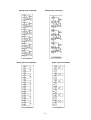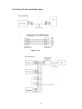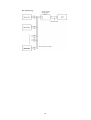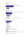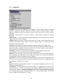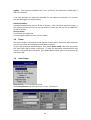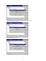
1
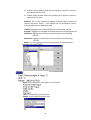
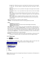
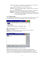
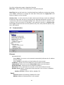
PR series
Quick User Manual
UMQPR01A
1st Edition, 07/2015
TABLE OF CONTENTS
1.
GENERAL DESCRIPTION ..................................................................... 5
1.1
UNIQUE FEATURES OF RECORDER ...................................................................................5
1.2
COMPARISON OF PR SERIES RECORDERS .......................................................................5
1.3
SMART MECHANISM .......................................................................................................6
2.
INSTALLATION AND WIRING ............................................................... 7
2.1
UNPACKING....................................................................................................................7
2.2
INSTALLATION ................................................................................................................7
2.3
PANEL MOUNTING STYLE ................................................................................................8
2.4
WIRING OF THE CARDS .................................................................................................11
2.5
RS-232, RS-422, AND RS-485 WIRING ........................................................................15
3.
CONFIGURATION................................................................................ 17
3.1
CHANNEL .....................................................................................................................18
3.1.1
Analog Input ........................................................................................................18
3.1.2
Digital Input .........................................................................................................21
3.1.3
Math Channel......................................................................................................23
3.1.4
Analog Output .....................................................................................................27
3.1.5
Digital Output ......................................................................................................27
3.1.6
External ...............................................................................................................28
3.1.7
Jobs.....................................................................................................................28
3.2
DISPLAY ......................................................................................................................29
3.2.1
Status Bar ...........................................................................................................31
3.3
TIMER ..........................................................................................................................32
3.4
CLOCK .........................................................................................................................32
3.5
COMMUNICATION ..........................................................................................................33
3.5.1
Connections ........................................................................................................35
3.5.2
Commands..........................................................................................................35
3.6
INSTRUMENT ................................................................................................................36
3.7
SECURITY ....................................................................................................................37
3.7.1
Normal.................................................................................................................37
3.7.2
CFR-21................................................................................................................37
3.8
DEMO ..........................................................................................................................38
3.9
AUTO-OUTPU ...............................................................................................................38
3.9.1
USB Printer .........................................................................................................39
3.9.2
Network Printer (LPT1) .......................................................................................40
3.9.3
Print Historical data .............................................................................................41
2
3.9.4
Print Reports .......................................................................................................42
3.9.5
Print Snapshot.....................................................................................................43
3.10
SYSTEM INFO ...........................................................................................................43
3.11
BATCH CONTROL ......................................................................................................45
3.12
CALIBRATE ...............................................................................................................47
3.13
PROCEDURE TO RESET AND RESTORE FACTORY DEFAULT SETTINGS ........................51
3.14
HANDWRITING MESSAGES ON TREND SCREENS .........................................................52
4.
WEBSERVER....................................................................................... 55
4.1
HOW TO CONFIGURE WEB SERVER SETTINGS ................................................................55
4.1.1
How to Configure Static IP Address....................................................................55
4.1.2
How to Enable Web Server.................................................................................56
4.2
HOW TO VIEW RECORDER DATA IN PC VIA WEBSERVER ................................................57
NOTE: IF THE USER REQUIRES TO KNOW THE FULL
DETAILS OF THE FUNCTIONS , PLEASE REFER
THE FULL USER MANUAL
3
Safety
This recorder is compliant with the requirements of EN61010-1, UL 61010C-1 & CSA
C22.2 No. 24-93. The protection provided by the recorder may be impaired if it is
used in a manner inconsistent with its intended purpose, or in an environment that
exceeds the specifications of the recorder. Future Design Controls is not liable if the
customer fails to comply with these requirements.
Safety Symbols
The following symbols may be seen in the user manual or on recorder labeling.
Caution
Protective Earth
DC Supply
Safety Notes and Precautions
1. Before any connection is made, the protective earth terminal should be connected
first. To avoid making the recorder dangerous under fault conditions, any
interruption of the protective Earth conductor inside or outside the recorder is
prohibited. Even in the case of a portable unit, the protective earth terminal must
remain connected if the recorder is connected to any hazardous voltage.
2. Keep signal and supply voltage wiring separated from one another. If this is
impractical, use shielded cables for signal wiring. Double insulation should be used
for signal wiring when the recorder is used with hazardous voltage.
3. Do not use the recorder where there is high vibration or a high magnetic field. This
could cause damage or error of measurement.
4. All maintenance or repairs should be carried out with power disconnected to avoid
personal injury or damage to the unit.
5. In areas with conductive pollution, adequate ventilation, filtering and sealing must
be installed.
6. When cleaning the recorder, handle carefully and use soft dry cloth. Avoid the use
of abrasives, or any sharp or hard objects which would damage the display.
7. Do not operate the recorder if any part has been removed or disassembled.
Consult your nearest dealer at once.
Static Electricity
Appropriate precautions must be taken when handling the recorder. The circuit
board components are susceptible to damage caused by electrostatic discharge.
Take static electricity precautions while handling and inserting USB memory into the
recorder.
4
1. General Description
1.1 Unique features of recorder
The PR series is a well-designed new generation paperless recorders with many
outstanding features as follows:
Hardware
•
•
•
•
•
•
•
•
•
•
•
•
•
•
•
•
Three sizes including 4.3”, 5.6〞and 12.1”
PR10, with a 4.3” display, with 3 or 6 universal analog inputs and 24 Optional
External Channels
PR20, with a 5.6” display, with 6, 12 , 18 or 24 universal analog inputs and 48
Optional External Channels
PR30, with a 12.1” display, with 6, 12, 18, 24, 30, 36, 42 or 48 universal analog
inputs and 96 Optional External Channels
TFT Color LCD, Touch screen & high resolution
100 millisecond sample rate and data logging
High accuracy 24-bit A-D Analog Input
16-bit D-A Analog Output
Digital input, maximum 100 Hz.
Plug & play I/O cards (AI, AO, DI, DO) for easy expansion
On-board SD card slot for Internal memory
USB slot for external storage
171 mm short depth
Ethernet as standard with optional RS-232 or RS422/RS485 communication
Two USB Host ports for downloading the data or connect to Printer
IP65 / NEMA 4X water-resistant
1.2 Comparison of PR series Recorders
Description
Display Size
Analog Inputs
(Maximum)
Math Channels
(Maximum)
External Channels
(Other devices)
Total Pages
Pens/Page
(Maximum)
Batches
(Maximum)
PR10
PR20
PR30
4.3”
5.6”
12.1”
6
24
48
15
40
60
24
48
96
8
20
21
6
6
10
1
1
1
5
1.3 Smart Mechanism
The recorded data is stored in the manufacturer’s special binary format. It is not
possible to manipulate or modify the recorded data. This feature fully guarantees
the security of the data.
Front View:
Rear View:
6
2. Installation and wiring
2.1
Unpacking
If any damage is found while unpacking, the user should contact the local
representative at once. It is suggested that the special packaging is retained for
possible future requirements.
2.2 Installation
Remove stains from this equipment using a soft, dry cloth. Do not use harsh
chemicals, volatile solvents such as thinner or strong detergents to clean the equipment
in order to avoid deformation.
The recorder is designed for indoor use and not in any hazardous area. It should be
kept away from shock, vibration, and electromagnetic fields such as variable
frequency drives, motors and transformers.
It is intended to operate under the following environmental conditions:
Pollution Degree Level II
Temperature
Humidity
Power
Altitude
IEC1010-1(EN61010-1)
0 ~ 50 ˚C
20 ~ 90 % RH (non-condensing)
90 ~ 250 VAC, 50/60 Hz or 11-36VDC
2000M maximum
7
2.3 Panel mounting style
PR10:
Front Side
Right Side
Panel Cut Out Dimensions
8
PR20:
Front Side
Right Side
Panel Cut Out Dimensions
9
PR30:
Front Side
Right Side
Panel Cut Out Dimensions
10
Portable styles:
2.4 Wiring of the cards
Wiring Precautions
1. Care must be taken to ensure that the maximum voltage rating specified on the
label is not exceeded.
2. For the panel-mount version, it is recommended that near an external fuse or an
external switch rated at 2A/250 VAC should be used.
3. Beware not to over tighten the terminals screws. The torque should not exceed
0.4 N-m (3.6 Lb-in or 4.0 Kg F-cm).
4. With the exception of the thermocouple wires, all wires should be stranded
copper conductor with maximum gauge of 18 AWG.
5. Connect a grounding conductor with 1.6mm diameter minimum to provide
protective grounding prior to turning on the equipment.
11
Analog Input Card AI206
Analog Input Card AI203
Relay output card (RO206)
Digital input card (DI206)
12
Relay output and digital input card (RD233)
Analog output card (AO206)
Note 1: The IO Cards should not be removed or Inserted to the recorder when the
power is ON. This should only be done when the recorder power is OFF.
Note 2: For Thermocouple Inputs, a 1 hour warm up is necessary for initial set up.
Note 3: Information regarding removing the IO Cards from the recorder.
For removing the IO Card, First remove the metal screws then plastic
screws, after that press the lock on the top and bottom of the Card and
pull to remove it. Failing to do so will damage the IO Card. Please follow
the below pictures for more information.
The Maximum Torque for the metal screw is 3Kg-cm (2.6in-lb) and the
Maximum Torque for the plastic screw is 0.8Kgf-cm (.7in-lb)
13
Note 4: For the PR30, Analog Input card should be inserted in slots 1 to 8 only.
AI Cards should not be inserted into slots 9 to 16.
Note 5: Circular Trends are only available for the PR30 mode
Note 6: In the PR30, the Analog Input card should be inserted in slots 1
to 8 only. It should not be inserted in slots 9 to 16.
Note 7: For some industries who prefer/favour circular displays, PR30 can offer this
unique feature and set the display speed for each page/circle in 30
minutes, 1, 2, 4, 8, 12 hours, 1, 2 days, or 1, 2, 4 weeks.
Note 8: Calibrate: Sometimes the field calibration is required for high accuracy. In
this case, a qualified engineer can do the necessary calibration.
14
2.5 RS-232, RS-422, and RS-485 wiring
Figure 2 – 24
15
16
3.
CONFIGURATION
(“Menu”), then the ”More” soft button to enter Configuration mode.
Press
Soft buttons
Enter key
Up directional key
Down directional key
Home key
Various options are available to enter into configuration mode
Option-1: Select the mode by pressing up & down directional keys, then press
“Enter” key
Option-2: Select the required mode directly with a touch, then press “Enter” key
Option-3: Select the required mode by pressing the mode two times quickly, it is
same as a double click from a mouse
Save: Save configuration from the recorder to a USB Stick or an SD Card.
To read the configuration from a USB Stick for the first time or any time the
configuration has been changed, it is important to press the “Save” soft button to
save configuration changes to the USB Stick or SD Card beforehand.
Load: Load configuration from a USB stick or SD Card to the recorder.
Default: If the configuration is set incorrectly, “Default” is a useful key to recall the
default settings for the analog input card inserted into rear expansion slot.
Home: Returns the User to the home page.
17
3.1
Channel
Path:
(Menu)-More-Config-Channel
This section is to configure different type of channels. Analog Input (AI), Digital Input
(DI), Math, Analog Output (AO), Digital Output and External device channels.
3.1.1 Analog Input
After entering the Configuration mode, in “Channel”, select “AI”, then Press the
“Enter” key to get into Analog Input Channel mode. It displays the Analog input
AI1 .Press directional keys〈 〉at the bottom to select other channels. Press
directional keys↑↓ on the right hand side to select the column. After completing
Configuration, press “Back” soft button, then press “Home” soft button to return to
main display. All configurations will be saved automatically.
Copy: For example, to copy the channel configuration from channel 1 to channel 2,
select the source channel, in this case AI1 (or whatever the channel is named),
press on “Copy” button. Now, a “Paste” button will get enabled, go to target
channel, say channel 2, and then press on “Paste” button.
Name: Enables the User to define the name for each channel with a maximum of
18 characters.
Desc: The description about a specific channel on the display.
Type: Option available to enable or disable the channel from selection
Filter: It is to reduce the noise of input signal before sampling. It is possible to
select range from 1 to 16 sec.
Log:
Data Type: 2 byte
2 byte range: -32767 to +32767
Trigger: Two options are available
18
a) Disable: Select disable while the recording of a specific channel is
not required at this time
b) Enable: Select Enable while the recording of a specific channel is
required at this time
Method: This is the method of logging measured data. Select the
column and press “enter”. Then choose the Log method of Instant,
Average, Minimum or Maximum data.
Instant: logging the last measured data at the sampling interval
Average: logging the averaged measured data at the sampling interval
Minimum: logging the minimum measured data at the sampling
interval
Maximum: logging the maximum measured data at the sampling
interval
Speed: It is the logging speed (recording speed) of measured data.
(Auto)Set Jobs under Events
Type: Select the sensor input type for the Channel.
Unit: The engineering unit of input.
Range: Select based on Sensor type
19
Scale: Appears only for linear inputs Ex: mV, Voltage, current etc..
Offset: It is offset value to correct the sensor error.
Gain: It is a multiplier to correct the sensor error.
The correct value = (the process value x gain) + offset
Events
Events are frequently used for Alarm purposes. Events can also be used for digital
outputs (DO), Timer, Totalizer, Counter or Report.
Maximum five events are possible to set for each Analog Input
Press “Add” to add new event
Press “Remove” to remove selected event
Type: There are various types of H, L, HH, LL, Dev+, Dev-, and Error to be selected
for a job or Alarm purpose
20
H: High limit. When the process is over high limit, the alarm or job is actuated.
L: Low limit. Any the process is lower than low limit, the alarm or job is
actuated
HH: High high limit, to set up another limit higher than high limit for double
warning.
LL: Low low limit, to set up another limit lower than low limit for double
warning.
Dev+: Trigger event on positive deviation of process value. The job or alarm is
activated when process value is deviated by greater than the setpoint+the
process value.
Dev-: Trigger event on negative deviation of process value .The job or alarm
is activated when the process value is deviated by less than the set point-the
process value.
Error: On channel error, an alarm or job is activated
Setpoint: To set up the process value for actuating Job1 and /or Job2
Alarm
Log Alarm: Record alarms
Log Alarm (Auto Ack): Record alarms and acknowledge automatically
Log Event: Record events
Job1, Job2: When an event occurs, the task to be performed is called the job. A
typical example is to trigger an alarm buzzer in the event of a high temperature.
Each pen can accept five different types of events (or alarms) and each event can
create two jobs. Please note that a job under Event is different from a job created
by pressing the Operate key. The former is actuated by an event, and the latter is
actuated by manual control, no event necessary.
Hysteresis: To avoid it been activated too often, the Log Alarm or relay can set for
no reaction. Hysteresis value can be defined for the event trigger set point
3.1.2 Digital Input
Path:
(Menu)-Config-DI
After entering the Configuration mode, in the Channel, select DI then Press the
“Enter” soft button to get into Digital Input Channel configuration page.
Name: Define the name for the Digital Input Channel. A maximum of 18 characters is
allowed for the name.
21
Description: Define detail description for the channel.
Type: Logic Level
Logic Level: This selection activates digital logic, which is either one or zero with low
frequency which is less than 1Hz, such as an external relay.
Pulse Counter: With this selection, we can feed high speed inputs (high Frequency, up
to 100Hz)
Select Logic Level and press “Enter” key
Events: A maximum of 2 events are supported for every digital Input channel.
A maximum of two jobs can be configured for each event.
*Note: Events will not appear if Logic Level selected as Pulse Counter
Add: Press “Add” to add events to the Digital Input
Remove: Press “Remove” to remove events from the Digital Input
Type: Select Low, L or High, H
Job1, Job2: To configure a Job, select Job1, the press the Enter button. It will show a
list of all the available jobs. Select the required Job.
Note: Number of digital inputs shown one t DI screen depends on number of Digital
input cards inserted in the paperless recorder.
Sample applications of Digital input …
After pressing a “Start” switch, latch ON Digital Ouput1
After pressing a “Pause” switch, latch Off Digital Output1
Start Timer, Stop Timer
Reset Totalizer, Reset Counter
Reset MaxMinAve values of all the channels etc..
It is possible to display Digital input status via status bar on any page in the
paperless recorder. If digital input is not enabled, it shows as “Low”. Presence of an
enabled digital input shall be shown as “High”. See the picture below.
To configure status bar, refer section “Display”
(Menu). Press “Status” and
Digital Input status can also monitored from the
then select “DI”, it will show the Digital Input Status as follows.
22
3.1.3 Math Channel
Maximum no. of Math channels in various Recorders are as follows
Recorder
Maximum Math
Channels
PR10
15
PR20
40
PR30
60
Path:
(Menu)-More-Config-Math
After entering the Configuration mode, in Channel, select Math, then Press the
“Enter” soft button to get into Math Channel configuration page.
Name: Define the name of the Math channel
Desc: Define the detail description for the channel name
Type: Specify either Math, Totalizer or Counter
Note: Based on selection at “Type”, configuration details will be changed. For ex:
Type=Math has different configuration details compared with Type = Totalizer or Type
= Counter
Log data type, Trigger, Method, Speed: Same as Analog Input
Press Back key and then press “Home” soft button go to Real time display and
memorize the Math settings.
23
Enter Expression column, it appears Source, Operator and a keyboard.
The Source covers all available Analog inputs, Digital Inputs, Math inputs, external
channels.
The Operators are mathematical expressions described below.
Use Source, Operator and keyboard to define the Math equation.
Transformation: Select disable, value or Math channel. This function mainly used to
display process values obtained from Non-linearization table
Table: Select disable, value or Math channel
Maximum 64 rows can be entered in the Transformation table
Ex: A chemical tank has a non-linear shape. The level is 0 to 1400 cms. The Recorder
should display 0 to 170 Tons as per following table
24
3.1.3.1 Counter
Path:
(Menu)-More-Config/Math
Select Type = Counter
Press directional keys〈 〉at the bottom to select one of the Math channel for the
Counter operation.
Name: Defines the name of counter, max. 18 characters allowed
Desc: Defines the description for a specific counter on the display
Type: Select Counter
Counter
Unit: Defines the unit of counter
Preset: Defines the preset value for the counter.
Event: Defines the type, Set point, Log, Job1 or Job2 & Hysteresis
Type: Select one of the options: H, L, HH, LL, Dev+, Dev-, Error
Set point: Defines the set point trigger of Counter value to initiate Jobs
and/or Log alarms
Log: Select Log Alarm, Log Alarm (Auto Ack.), or Log Event
Job1, Job2: various jobs can be assigned, 2 jobs for each counter
Hysteresis: To avoid jobs have been activated too often, it can set for no
reaction.
3.1.3.2 Totalizer
In our new generation Recorder, the Totalizer is a part of Math channels.
Configuration Path:
(Menu)-More-Config-Math
Select Type = Totalizer
25
Press directional keys〈 〉at the bottom to select from available Totalizers
Name: Defines the name of the Totalizer, Maximum 18 characters allowed
Desc: Defines the description for a specific Totalizer on the display
Type: Select “Totalizer”
Log: Same as Analog input configuration
Totalizer:
Input: Analog Input (AI) or Pulse Counter (DI)
Source:
Select
the
source
for
the
input/Math/Counter/Totalizer
Action: Disables or enables the Totalizer
Totalizer
from
Analog
Decimal: Defines the decimal point for the Totalizer
Period: Selects if seconds, minutes or hours are used for the Totalizer
Unit: Defines the unit of totalizing
Preset: Defines the preset value for the Totalizer.
Low Cut: Defines the Low Cut for the Totalizer.
For ex: If 0.0 is set as Low cut, then, if source channel AI1 is less than 0.0, the
Totalizer value will not go to negative.
26
Event: Total 5 events are supported for each Math channel. Defines the
type, Set point, Log, Job1 or Job2 & Hysteresis
Type: Select one of options, H, L, HH, LL, Dev+, Dev-, Error
Set point: Defines the set point trigger of Totalizer value to initiate Jobs
and/or Log alarms
Log: User can select one of Log Alarm, Log Alarm (Auto Ack.), or Log Event
Job1, Job2: various jobs can be configured, 2 jobs for each Totalizer
Hysteresis: To avoid jobs from being activated too often, the hysteresis can
set to avoid nuisance tripping. Hysteresis values can be defined
for the event trigger set point.
3.1.4 Analog Output
After entering the Configuration screen, in the Channel section, select AO, then Press
the “Enter” soft button to get into Analog Output Channel configuration page.
Desc: Define detail description for the channel name
Type: Current, Voltage
Output: Select either disable, 0 to 20mA , 4-20mA, 0-5V, 1-5V, 0-10VDC
Expression: This is similar to Math channel.
3.1.5 Digital Output
Desc: Define detail description for the channel name
Reverse: Enable this if Reverse operation is required for the Digital Output.
For ex: If reverse is disabled, the relay output is Normally Open (NO). In case if you
need to have a Normally Closed (NC) relay at Recorder Power ON, then enable
“Reverse” for the selected Digital Output. The Relay output shall be normally closed.
27
3.1.6 External
This is to access data from the external devices.
Maximum no. of external channels in various Recorders are as follows
Recorder
PR10
PR20
PR30
Maximum External
24
48
96
Channels
All the properties are similar to Analog Input channel.
More details about external channels are available at section “Communication”
Please refer Detail Manual section “Communication” for examples of external
channels.
3.1.7 Jobs
Various types of jobs can be selected as follows.
No Action: Do nothing
Send Email: Send Email directly from Recorder
Pause: Stop logging data.
Start: Start logging data.
Sound Buzzer: Sound the buzzer. It stops once any key is pressed.
Dump Data: To dump data from internal memory to external memory.
DO Latch On: Set digital output / relay on, and then select Target, let’s say from
one of DO 1 to DO 6. The relay is latched when it is activated.
DO Latch Off: Set digital output / relay off, and then select Target, let’s say from
one of DO 1 to DO 6. The relay is un-latched when it is activated.
DO Process: Set digital output / relay on for process high or low, and then select
the target, let’s say from 1 of DO 1 to DO 6. The relay is not going to be latched
when it is activated.
Enable Timer: Start the timer, and then select Target timers
Disable Timer: Stop the timer, and then select Target from Timers
Preset Totalizer: set a preset value to the target Totalizer.
Reset Totalizer: Reset Totalizer to zero. Select a single Target Totalizer or All totalizers
Enable Totalizer: Starts the Totalizer. Select a single Target Totalizer or All totalizers
Disable Totalizer: Stops the Totalizer. Select a single Target Totalizer or All totalizers
28
Preset Counter: set a preset value to the target counter.
Reset Counter: Resets the counter to zero. Select a single Target counter or all
counters
Inc Counter: Increases the counter by 1. Select a Target counter or all counters
Dec Counter: Decrease the counter by 1. Select a Target counter or all counters
Log Report: Make a report for Counter, Totalizer, Analog inputs (Min/Max/Avg),
Math (Min/Max/Avg), All Counters, All Totalizers, and All Channels
(Min/Max/Avg). Choose this column, and the report will be presented as
described in section “Reports”.
Reset MinMaxAve: In the Report function, after logging the Min/Max/Avg data of
AI and Math channels for one day for example, this will reset historical data in
order to log new data for the next day. It is also possible to reset the
Min/Max/Avg for “All Channels” at one step.
Print: If a printer is connected to the Paperless Recorder via the USB port or
Ethernet, the following print jobs can be triggered from “events”
Print Historical data
Print Event List
Print Report List
Print Snapshot
The time period of Print depends on the configuration available at
(Menu)-More-Config-Auto-Output
Note: Please refer section “Auto Output” for more details about options available
Note:
Press “Home” key to return to real-time display, all configurations will be
memorized
◆ The Digital output DO card with relays can be set in Job1 and/or Job2. It can be
viewed in “System Info” mode after it is installed into a Slot.
3.2
Path:
Display
(Menu)-More-Config-Display
Select “Display”, then press the “Enter” Soft button to get into the Display mode
configuration page (shown on the following page).
Display pages
Pens/Page
PR10
8
6
PR20
20
6
29
PR30
21
10
Name: Defines the name of the display page
Mode: Defines the default method of displaying data for the page.
Options are: Trend, Bar, Digital, Mix, Circular (only for PR30) and Disable
modes.
* Circular Trends are only available in the PR30 model.
For Circular Trends
Speed: This is the display speed. Available options are 100 msec/dot, 1 Sec/dot, 2
Sec/dot, 5 Sec/dot, 10 Sec/dot, 20 Sec/dot, 30 Sec/dot, 1 min/dot, 5 min/dot, 10
min/Page, 30 min/Page, 1 hour/Page, 2 hour/Page, 4 hour/Page, 8 hour/Page, 12
hour/Page and 1 Day/Page.
Direction: Sets the trend direction to be horizontal or vertical.
Background: Sets the background color of Trend mode to black or white
Pen: For a specific channel, this defines the drawing pen, its color, width, Range Low
and Range High for the display.
Channel: Selects a specific analog input, Math, Counter, Totalizer, External
channels. Select Disable if a specific channel is not required to be displayed.
30
Color: Selects the color for each pen.
Width: Selects the width of trend, 1-thin, 2-medium, 3-wide.
Low: Defines the low scale for a pen on the display.
High: Defines the high scale for a pen on the display.
Note:
◆ To illustrate the difference between Display Hi, Display Lo, Scale Hi, and Scale
Low, here is a typical example, with input 0-10V, Scale Low=0.00, Scale
Hi=100.00, to have better resolution and vision on Bar, set the Display Lo=0.00
and Display Hi=50.00 so that the Bar displays from value 0.00 to 50.00.
◆
The decimal point is defined by Scale Hi and Scale Low, and not by Display Hi, or
Display Lo.
3.2.1 Status Bar
Status Bar: To make it convenient when viewing the status of Digital Input, Digital
Output, Math channel, Totalizer, Counter and AO, the user may enable these items in
the status bar. The Status bar is displayed at Lower part of the page. A maximum of 10
tags can be displayed in each Status bar. One status bar can be configured for each
page.
Note: Status bar configuration is not shared in all the pages. You may define a
different setup for status bars in each page per your requirements.
Fig: Status bar display in Real time
31
3.3
Timer
Path:
(Menu)-More-Config-Timer
Press directional keys〈 〉at the bottom to select from one of 20 available timers
Type: Countdown, Repeat Countdown, Daily, Weekly or Monthly.
Countdown: Defines the interval of time, e.g. days, hours, minutes and seconds.
(Not the Actual Time)
Repeat Countdown: Repeats the previous countdown (Not the Actual Time)
Daily, Weekly or Monthly: The timer works in selected interval of Real Time.
Action: Disables or enables the timer.
Job1, Job2: 2 jobs can be configured for each timer.
3.4
Path:
Clock
(Menu)-More-Config-Clock
32
Fig: Clock configuration page in Paperless Recorder
Date Style: Selects either month/date/year or date/month/year
Date/Time: Set up the local time. Use directional keys Up/Down to select the column,
press “Enter” soft button to change the clock data. Then press the “Apply Time” Soft
button to apply it to the recorder.
Summer time: In some countries of North America and Europe, clocks are adjusted
forward one hour near the start of spring and are adjusted backward in autumn. This
is commonly referred to as Daylight Savings Time. We refer to this as “Summer Time”.
A Summer time set provision is available in the paperless recorder. In Summer time,
Select Type: Enable and then set Start (Month, Day, Hour, Min) and End (Month, Day,
Hour, Min) details.
3.5
Communication
Ethernet
IP: DHCP/STATIC
Select DHCP if the server on the network automatically allocates the IP address
for the recorder.
Select STATIC to manually set a fixed address for the recorder.
IP Address: Defines the current address of the recorder on the network
Subnet Mask: Defines the current Subnet Mask address on the network
Default Gateway: Defines the current Gateway address.
DNS Server: This is required if the recorder is to be connected to Internet
Modbus Server: When configured as Slave Recorder is act as Server in Modbus
Connectivity
Modbus TCP Port: Default: 502 for Modbus TCP
Serial:
Protocol: Modbus RTU Master/ Modbus RTU Slave
Address: Address of Master/Slave in the network
33
Baud rate: 9600/14400/19200/38400/57600/115200
Data format: None, 8, 1 or Odd, 8, 1 or Even, 8, 1
Modbus Client/Master:
Sample Rate:
Ethernet: 100 msec/dot, 1 sec/dot, 2 sec/Dot, 5 sec/dot, 10 sec/dot
Timeout : The default timeout is 100ms
Serial: 100 msec/dot, 1 sec/dot, 2 sec/Dot, 5 sec/dot, 10 sec/dot
Timeout : The default timeout is 100ms
Interval between 2 commands : The default timeout is 10ms
Email: Enable/Disable
Press’ “Email Test” and check mail function
If any problems with Email delivery, it will show error as shown attached
34
3.5.1 Connections
There are a total of 16 connections available
Each connection can be configured as either Serial or Ethernet
Name: Connection name
Type: Serial/Ethernet
Slave ID: If Recorder is Modbus RTU Master, then, all the Slaves need to be
configured in the connections.
IP: This is enabled only if Type = Ethernet selected at any connection.
3.5.2 Commands
A total of 16 commands are available
Action: Enable/Disable
To Channel:
First: Enter first external channel details, Ex : Ext1
Last: Enter last external channel details, Ex: Ext24
From Device
Register:
Start: Address: Enter Start register address
Data Type: Int16/Uint16/Int32_B/Int32_L, UInt32_B, UInt32_L, Float_B,
Float_L
Connection: Select the required connectio
35
3.6
Instrument
Language: A total of 19 languages are supported. They include English, Simplified
Chinese, Traditional Chinese, Japanese, Korean, French, German, Italian, Polish,
Spanish, Portuguese, Brazil Portuguese, Russian, Thai, Czech, Danish, Dutch, Swedish
& Turkish
Security: Select Normal or CFR-21 security. More details available at section
“Security”
Batch Control: Disable and Enable options available for the selection. Refer section
“Batch Control” for more details.
Volume: When the screen is touched, you can hear a “beep” sound. Select Disable to
switch off the beeper. Select value 1 to 10 for volume control. 1 is minimum sound
and 10 for maximum sound
Tool bar: On left side of the display page, the tool bar appears for configuration.
Auto Hide: Select 10 Sec or 20 Sec or 30 Sec or 60 Sec to hide the tool bar if the user
does not operate recorder via touch screen for the set time interval. Select “disable”
if auto-hide is not required on specific set time
Scan Page: The User can set Automatic scanning of display pages for fixed time
when enabled . The Fixed times are 1minute to 10 minutes.
Idle time: If touch screen is not used for the set idle time, then the display pages will
start scrolling as per defined scan rate. Select 1 to 10 Min. for the idle time if display
scroll feature is required, otherwise select “disable”.
Scan Rate: This is the scroll time for the display pages. Select a time interval between
5 sec to 30 sec. This time interval is effective only if the “idle time” is enabled and the
selected time is between 1 to 10 min
LCD:
Brightness: Select level between 0 and 6. 0 is the lowest brightness and 6 is for the
highest possible brightness.
Screensaver: To prolong the life of the LCD display, it is suggested to set the display
turn-off time to 1, 10, 20, 30, 40, 50 or 60 minutes after the last time the user
operates the recorder. Screensaver default time is set to 10minutes from the factory.
The recorder continues to record data while it is in screen saving mode. The display
turns on again by touching the LCD screen
36
Storage: Select internal flash memory or SD card
Custom page: User can use this setting to enable or disable custom pages
downloaded via Ethernet.
Allow download via Ethernet: Enable/disable
3.7
Security
3.7.1 Normal
Path:
(Menu)-More-Config-select Instrument, then press “Enter”
Select “Security” = Normal
If normal security is selected, users will need to key in a common password with a
maximum of 18 characters. Once the password has been entered, the user needs to
key in the password whenever Config, Dump, Clear or Operate soft keys are required.
These keys enable the user to do configuration, dump data, clear data or manually
operate the job. For easy access Config, Dump, Clear or Operate soft keys, the user
may ignore the password by leaving the password field blank. If a password is not
entered initially, there is no password required.
How to enter simple password
(Menu)-More-Config, select Password, press “Enter”, then key-in the passwor
3.7.2 CFR-21
If the higher security CFR-21 is selected, it requires the recorder to operate with more
restricted rules which comply with FDA 21 CFR Part 11
It has time limit during operation. If the user does not press ay keys in a predefined
period of time (which can be selected between 1 to 20 minutes using LogOut
function), the user needs to key in the password again. It also offers an audit trail
function to record the user, the timing, and what type work the user was doing on the
recorder. Incorrect password and unauthorized operation will be recorded into the
event list as well.The maximum number of users available in FDA 21 CFR Part 11
Security Mode is 30.
In
(Menu)-More-Config-Select Instrument, press “Enter” soft button.
Select Security = CFR-21.
37
LogOut: Time selection available from 1 min. to 20 min. This selection is visible only if
CFR-21 is selected.
If no user operates the Paperless Recorder for the above set duration, the current
user will be logged out automatically
Password validity:
Password validity can be set for 30, 60 or 90 days. After the preset amount of days, it
will require the user to key in a new password, or keep the old one for an additional
30, 60 or 90 days.
Security levels:
0 to 9 levels are supported
9 is the highest authority level, 0 is the lowest
3.8 Demo
The Demo mode is a simulation mode used as a sales tool for demonstration purposes.
It is set to simulate AI analog inputs and Math functions.
To start the automatic demonstration, first enable Demo mode, then turn the power
OFF and Power ON to make it effective. To stop the automatic demonstration and
return to real mode with real inputs, first disable Demo mode, then turn the power off
and Power ON.
3.9
Auto-Outpu
Setup Printer: It is to configure printer
Select Setup Printer and then press the “Enter” soft button
38
Two kinds of printers are supported. One is USB printer for page printing and
another is Serial printer for Line printing.
Applications: Print Historical data, events, & Reports and snapshot directly from
Paperless Recorder.
3.9.1 USB Printer
Generally, USB printer support PCL protocol. It means, it will support Page Print, but
not line print. We support PCL language 4, 5 & 6.
If USB printer supports ESCP protocol similar to EPSON LQ300+, then, it is possible to
take line print.
Please refer Printer user manual for exact protocol details
Do not use USB printer supporting only PCL to print single line alarms,
otherwise, pages will be wasted
Procedure
Connect Recorder to Printer via USB cable
Power ON Printer
(Menu)-More-Config-Auto-Print, Enter
Path:
Select “Setup Printer”, press “Enter” soft butto
39
Printer: PCL Laser, ESCP printer, PCL Inkjet available by default. Select one from the
list as per printer model connected to the Paperless Recorder
Port: It shows “Network” by default. Once a printer is connected to the USB port, it
will show “LPT1” for the USB printer. Select “LPT1”
Net Path: It is required to enter the correct network path here only if both Printer
and Paperless Recorder are connected to a LAN network
Paper Size: A4, B5, Legal and Letter are supported
Draft mode: By default, it is selected. If more quality print is required, deselect Draft
Mode
Color: Enabled for Inkjet printer
Orientation: Select Portrait/Landscape as per requirements
Note: Margins & Print Range are not working at this time.
Now, setup is ready at Paperless Recorder
3.9.2 Network Printer (LPT1)
Serial printer will print minimum one line and is generally used for printing Real time
alarms. Also, it can be used for printing historical data and alarms from the Paperless
Recorder. ESCP language id supported, so any printer supporting ESCP like LQ300+
can be used. The LPT1 port of a PC can be connected to a Serial printer directly.
However, it needs to have a Printer driver installed in PC first, and share it for
network use via Ethernet.
Procedure
Connect Paperless Recorder to PC via Ethernet
Install Printer driver in PC. Share Printer for network use
Connect Printer to PC via LPT1
Power ON Printer
(Menu)-More-Config-Auto-Print, Enter
In Paperless Recorder, at Path, select
40
Select “Setup Printer”, press “Enter” soft button
Select ESCP printer.
Then, enter the proper Net Path. Ex: \\PC1\LQ300
PC1 is computer name and LQ300 is shared printer driver for network use
Now, the setup is ready at the Paperless Recorder
3.9.3 Print Historical data
Configure USB Printer or Network printer as explained in earlier section
In Paperless Recorder, at Path, select
(Menu) -More-Config-Auto-Output,
Enter
41
Period: Select Last hours or Last days
Hours/Days: Select no. of hours or no. of days as per above selection
Interval: Select intervals of 100 msec/1 sec/2 sec/ 5sec/ 10 sec/ 20 sec/ 30 sec/ 1
min/ 5 min/ 10 min.
The Print function is available in the Job list and can be initiated in various ways.
Ex: Print historical data of last 1 hr. and do this every day at 8.00 hrs
3.9.4 Print Reports
In Paperless Recorder, at Path, select
Enter
(Menu)-More-Config-Auto-Output,
In the Mode, select which kind of Reports are required. Available options include
Daily Reports, Weekly Reports and Monthly Reports
42
3.9.5 Print Snapshot
(Menu)-More-Operate-Print Snapshot
3.10 System Info
Path:
(Menu)-More-Config-System Information
The system information includes System version, Internal and External memory,
Ethernet IP address and Slots status
Version: The firmware version of the recorder.
Memory (Free / Total):
Internal: Indicates the percentage of free memory compared to total memory
available in internal flash card
External: Indicates the percentage of free memory compared to total memory
available in external memory devices of SD and USB.
A small icon on the top right indicates the percentage of free memory e.g.: Mem 96 %
Address:
MAC: Displays the MAC address of Paperless Recorder
IP address: Displays the IP address for the Paperless Recorder
Slot 1..5: Indicates the status of all Slots and the cards that have been inserted. The
cards include Analog Input AI, Digital Input DI and Digital Output DO & AO.
43
3.10.1.1 Upgrade Firmware
Path:
(Menu)-More-Config-System Information-Maintain
Maintain: The Maintain button is located at left lower side in System Info. page. It is
the button to upgrade the firmware and calibrate the touch screen in the paperless
recorder
Upgrade Core System:
This is to upgrade firmware in the paperless recorder. Contact factory/supplier for the
latest firmware files. Please download firmware file to a USB stick or SD Card then,
insert the USB stick into USB port or SD Card at SD card Slot in the Paperless Recorder.
Select the External Storage to SD Card or USB flash on the External Storage Setting
depends on the storage inserted. Select “Update Core System”, then click the “OK”
button. It may take a few seconds to finish the process. Please note that the power to
the recordershould be not switched off during this upgrade process
3.10.1.2 Calibrate Touch Screen
Path:
(Menu)-More-Config-System Information-Maintain
Maintain: The Maintain button is located at left lower side in System Info. page. It is
the button to upgrade the firmware and Calibrate touch screen in paperless recorder
This is used to calibrate the touch screen. A “+” symbol appears in the center of the
LCD screen. Carefully press and briefly hold a stylus or finger on the center of the
target. Repeat this procedure as the target moves around the screen. Just touch the
44
screen to complete the screen calibration. This procedure helps to locate pointer via
touch screen and properly select the objects during operation of the recorder
3.11 Batch Control
This feature is to store data in a different folder for every batch and archive data
later with reference to a batch.
(Menu) - More-Config- Instrument
Path:
Select Batch Control and press “Enter” key. Select “Enable”. Press “Ok”
Press “Back”
45
Press “OK”, then, press “Home” Soft key to save these settings
Power the recorder OFF then ON, then in the
(Menu), the Batch soft key
will be shown as below
Note: “Batch” soft key will appear only after Batch Control enabled as explained
above
Press on Batch and it shows the following screen
Operator can enter a maximum of three comments for any batch.
In the
(Menu)-More-Config, select “Batch”, press “Enter” key
It will show the Batch control settings as shown below
Name: Enter Batch name. A maximum of 18 characters is allowed. By default, the
name is Batch1.
46
Lot Number: Enter the Lot number. If Auto increment is enabled, then Lot numbers
will be incremented automatically by the recorder, Batch1-1, Batch1-2,
Batch1-3 etc. during every start of a new batch
Jobs: Two events, Start, Stop are available
Start: Start means Jobs that should be done during start of a new batch
Stop: Stop means Jobs that should be done during stop of a batch
Note: When batch control is enabled, the recorder will be in Pause mode by default
initially and it requires Starting of the recorder from the Menu by pressing at
(Menu) - More than “Start”. When recorder is not logging any data, Pause
status shall be shown in the Top right area of the recorder as shown below
How to do the batch control
(“Menu”), “More”, then “Start”. Batch number will be shown in the
Press on
recorder Top area.
To Stop this batch, press on “Menu”, “More”, then “Pause”. It gives a message
“Saving data” and updates batch data in the internal memory of the paperless
recorder.
3.12 Calibrate
This function is used for calibrating Individual Analog channel.
Below we have shown only one example for more AI,AO calibration examples,
please refer to Detailed manual.
Example 1
Calibrate an AI with K-Type Thermocuple
Please note that , Inorder to calibrate the whole Module slot accurately , the 3rd
channel of each slot nust be calibrated first. Click
47
When you click Calibrate menu, the user can see the below screen. Please click
calibrate as shown in the below screen
Click yes and proceed with the calibration process
Please follow the next instruction, input 0 mV in to the input which can be seen in
below screen
48
After you input 0V and select ok, the user can see the below screen.
Now follow the next instruction.
Now input 60mV and click ok
49
After you input 60 mV and select ok, the user can see the below screen
Now follow the next instruction.
When the calibration is done successfully, the user can see below screen
Note:
Channell #3 should be calibrated first in all types of Analog Input cards.
An analog temperature sensor is installed in channel # 3. When channel # 3 is
calibrating, the cold junction voltage measured by this temperature sensor will be
loaded into a register.
If channel # 3 is not calibrated, the default value of cold junction voltage will be used
for all channels. It does not matter what order you perform calibration after
calibrating input 3, there is no need to follow a sequence, and any one of T/C, RTD,
mA or VDC can be done independently.
50
3.13 Procedure To Reset and Restore Factory Default Settings
Power ON the Recorder while Pressing the Reset Button
Now the Screen will appear like below
Format:
Press the Format Button for at least 3 Seconds to return the Recorder to factory
Settings.
After the Recorder is done formatting, it will ask for Screen Calibration.
Do the Screen Calibration.
The recorder has now been returned to factory default settings.
Upgrade:
Download the Firmware from the FTP Link Given
Copy the File to the SD Card. Be sure the SD card is formatted to FAT32.
Insert the SD Card to the SD Card Slot on the Recorder.
Press Upgrade Button for at least 3 Seconds to upgrade the image from SD Card.
Follow the on-Screen instructions
51
3.14 Handwriting Messages on Trend Screens
Handwriting Messages on Trend Screens is very handy for process associates to
highlight important events.
This is shown in the below picture.
When the User navigates through
(Menu) History
Page 1, as
shown in the below screen.
If the User wants to write a message, they can press the pen symbol as shown in the
red square in the screen below
Then using the stylus, the User can write any message in Historical Trend Pages as
shown below.
52
If the User wants to change the width of the written message, he/she can choose
the width of pen as shown in the screen below. The menu to change the width is
shown by the arrow pointing to the red box.
If the User wants to change color of the pen, he/she can change it by pressing the
menu shown in the red box in the picture below.
If the User wants to erase part of a message, he/she can do this by pressing the
menu (shown in the red box in the picture below), and erase part of the message.
53
If the User wants to undo part of a message, he/she can do this by pressing the undo
symbol (shown in the red box in the picture below). This will undo the last part of
the message.
If the User wants to delete the written message, he/she can this do by pressing the
delete symbol (shown in the red box in the picture below), and this will delete the
written message.
If the User wants to save the written message, he/she can do this by pressing the
“save” symbol (shown in the red box in the picture below). This will save the written
message.
54
4. WEBSERVER
It is used to view Paperless Recorder from a Remote location via Internet.
4.1 How to configure Web server Settings
For using Web server application in the Recorder, Configuring the Recorder for a
static IP address, and enabling the Web server.
4.1.1 How to Configure Static IP Address
In the Configuration screen, select “Communication”, then press the “Enter” soft key
Select IP type = User Define.
Enter the IP Address, Subnet Mask, Default Gateway, and DNS Server Settings in the
Ethernet Settings.
Note: Make sure to enter Global, Unique, static fix IP address received from Internet
solution provider.
55
4.1.2 How to Enable Web Server
Select Web Server Menu in the Communication screen.
Enable the Web Server for using Web Server application in the Recorder.
After completing the above steps, press the “BACK” key, then the “Home” key to
return to the main menu. It will save the configuration settings in the Recorder.
Now the Recorder is ready for the Web Server Applications.
Note: The Web Server update time on the browser is 1 second for real time data and
statuses and 5 Seconds for Alarms.
56
4.2 How to View Recorder Data in PC via Webserver
Connect Paperless Recorder to the Internet
Open the browser (Internet Explorer 10 or Google Chrome) in the PC
Enter the IP address of the Recorder in the address bar of the browser.
Format: http://192.168.1.111
Now you can see the Paperless Recorder screens in browser as shown below
The display includes Real time values of all channels like AI, Math, Counters,
Totalizers, Real time alarms, historical alarms, status of Digital Inputs, Digital
Outputs, Analog Outputs, Counters, and Totalizers etc...
Press Overview to view the summary of all data in single screen
57
By pressing “Mode”, you can view the data in Bar Graphs, Trends and Digital Values.
By Pressing Trend you can view the data in trends.
By pressing “Bar”, you can view the data in Bar Graphs
58
By pressing “Digit”, you can view the Data in the digital format
By pressing “Alarm”, you can view the List of Alarms along with the detail
59
By pressing “Status”, you can view the status of the Analog outputs, Digital Inputs,
Digital Outputs, Counters and Totalizers.
By pressing “DI”, you can view the status of the Digital Inputs
By pressing “DO”, you can view the status of the Digital outputs
By pressing “AO”, you can view the status of the Analog Outputs
By pressing “Counters”, you can view the status of the counters
60
By pressing “Totalizers” you can view the status of the totalizers.
61
Warranty:
Future Design Controls PR Series Paperless Recorders are warranted to be
free from functional defects in materials and workmanship at the time the
products leave Future Design Controls facilities and to conform at that time to
the specifications set forth in the relevant Future Design Controls manual,
sheet or sheets for a period of Two years after delivery to the first purchaser
for use.
There are no expressed or implied Warranties extending beyond the
Warranties herein and above set forth.
Limitations
Future Design Controls provides no warranty or representations of any sort
regarding the fitness of use or application of its products by the purchaser.
Users are responsible for the selection, suitability of the products for their
application or use of Future Design Controls products.
Future Design Controls shall not be liable for any damages or losses, whether
direct, indirect, incidental, special, consequential or any other damages, costs
or expenses excepting only the cost or expense of repair or replacement of
Future Design Control products as described below.
Future Design Controls sole responsibility under the warranty, at Future
Design Controls option, is limited to replacement or repair, free of charge, or
refund of purchase price within the warranty period specified. This warranty
does not apply to damage resulting from transportation, alteration, misuse or
abuse.
Future Design Controls reserves the right to make changes without
notification to purchaser to materials or processing that do not affect
compliance with any applicable specifications.
Return Material Authorization:
Contact Future Design Controls for Return Material Authorization Number
prior to returning any product to our facility.
Future Design Controls, Inc.
7524 West 98th Place, P.O. Box 1196, Bridgeview, IL 60455 USA
888.751.5444 - Office:
888.307.8014 - Fax
866.342.5332 - Technical Support
E-mail: [email protected]
Website: http://www.futuredesigncontrols.com
62