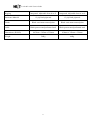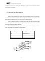
1
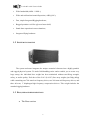
USER’S GUIDE LA12 & LA12C Version 2.0 LA12 & LA12C User’s Guide TECHNICAL SUPPORT If you have a question about line arrays or run into a problem using one of our line arrays, call our technical support team. Phone: +351 224 890 075 Monday through Friday between 8:30 AM and 6:30 PM. E-mail: [email protected] 2 LA12 & LA12C User’s Guide Table of contents TABLE OF CONTENTS ...................................................................................................................................... 3 1. 2. 3. 4. 5. INTRODUCTION ........................................................................................................................................ 5 1.1 MAIN FEATURES ..................................................................................................................................... 5 1.2 SYSTEM ENCLOSURE .............................................................................................................................. 6 1.3 BASS, MID AND HIGH SECTIONS .............................................................................................................. 6 1.4 BOX DESCRIPTION AND DIMENSIONS ...................................................................................................... 8 1.5 OUTDOOR EXPOSURE.............................................................................................................................. 9 1.6 INPUT CONNECTOR PANEL ..................................................................................................................... 9 1.7 LA12 (LA12C) LINE ARRAY ELEMENT SPECIFICATIONS FOR A SINGLE ENCLOSURE ............................. 10 SYSTEM CONNECTION, AMPLIFICATION AND DIGITAL PROCESSING ............................... 12 2.1 POWER AMPLIFIER ............................................................................................................................... 12 2.2 NEXT LMS240I DIGITAL PROCESSOR .................................................................................................. 13 2.3 SPEAKER CABLE REQUIREMENTS ......................................................................................................... 16 RIGGING.................................................................................................................................................... 17 3.1 SAFETY WARNING................................................................................................................................ 17 3.2 FLYING LOUDSPEAKERS SAFELY........................................................................................................... 18 3.3 GROUND STACKING LOUDSPEAKERS SAFELY ........................................................................................ 19 3.4 TRAINING & EDUCATION ..................................................................................................................... 20 3.5 RIGGING SYSTEM OVERVIEW ................................................................................................................ 20 3.6 FLYING HARDWARE .............................................................................................................................. 20 3.7 QUICK – RELEASE PINS ......................................................................................................................... 21 3.8 FLYING BAR.......................................................................................................................................... 21 3.9 SWING ARMS ........................................................................................................................................ 22 3.10 RIGGING SLOTS .................................................................................................................................... 22 RIGGING SETUP PROCEDURES ......................................................................................................... 23 4.1 FLOWN INSTALLATION ......................................................................................................................... 23 4.2 GROUND STACKING .............................................................................................................................. 26 MAINTENANCE ....................................................................................................................................... 28 5.1 RIGGING SYSTEM .................................................................................................................................. 28 5.2 ENCLOSURE CLEANING ......................................................................................................................... 29 5.3 TRANSDUCERS ..................................................................................................................................... 29 5.4 SPARE PARTS ........................................................................................................................................ 29 3 LA12 & LA12C User’s Guide PLEASE take a little time to learn how to get great results with your NEXT LA12 (LA12C) System. It’s a small investment that will generate a large payoff: more satisfied clients, more efficient operations and better recognition for your skill as a sound reinforcement professional. 4 LA12 & LA12C User’s Guide 1. INTRODUCTION NEXT-proaudio LA12 (LA12C) line array is a next generation line array system which combine innovative loudspeaker design techniques with line array technology to produce a very powerful with extended frequency response, smooth coverage and maximum dynamic impact line array. 1.1 MAIN FEATURES 3 way all horn loaded Line Array system; High SPL and low distortion; Very smooth and clear sound; Excellent and highly predictable dispersion control over a wide bandwidth; Great and deep bass impact thanks to the double tuned bass cabinet; One piece molded Mid/High section for strength and accuracy; 5 LA12 & LA12C User’s Guide Wide bandwidth (60Hz - 19kHz ); Wide and uniform horizontal dispersion (-6dB @ 90º); Fast, simple Integrated Rigging hardware; Rugged premium void free plywood outer shell; Stand alone operation in most situations; Integrated flying hardware. 1.2 SYSTEM ENCLOSURE The system enclosure integrates the unique acoustical elements into a highly portable and rugged physical system. To make field handling easier and to enable you to create very large arrays, the individual box weight has been minimized without sacrificing strength, safety, or audio quality. Each box of the LA12 (LA12C) line array weights just 54kg (46kg) while containing one 700-watt low frequency driver, two 280-watt mid frequency drivers, and three 60-watt, 1” diaphragm high frequency compression drivers. This weight includes the attached rigging hardware. 1.3 BASS, MID AND HIGH SECTIONS The Bass section 6 LA12 & LA12C User’s Guide The LA12 (LA12C) line array system features a 12" Neodymium high excursion high power bass loudspeaker loaded by a DOUBLE TECHNOLOGY CABINET that perfectly matches the very high efficiency and impact of a horn reproduction with the soft extended bass response of the reflex loading. The Mid section For the mid we use 2 special 6.5" speakers with two PRISMATIC PHASE CORRECTION DEVICES, mounted in a 90º horizontal dispersion wave guide. The prismatic phases devices besides the phase correction also makes the system behave like a four sound sources and so agreeing with the second line arrays condition: The distance between the sound sources must be less than half a wave length of the higher frequency it must reproduce. 7 LA12 & LA12C User’s Guide The High section The HF reproduction is assured by three 1" drivers loaded by a proprietary wave converter with path length equalization, the ICWG, that transforms the spheric waves into cylindrical isophasic waves coupling seamlessly with the others high frequency transducers of the array. The ICWG output directly feed a special 90º horizontal dispersion wave guide. 1.4 BOX DESCRIPTION AND DIMENSIONS The NEXT LA12 (LA12C) measures only 1087mm x 395mm x 550mm (838mm x 395mm x 550mm), each enclosure includes all the required rigging hardware and fittings needed to couple one box to another. In the drawing shown below there is a front, top and side view of the enclosure. Designed as a Line Array Element, the NEXT LA12 (LA12C) is intended to be used in multi-box arrays. Due to its trapezoidal shape, these LA12 (LA12C) arrays have an important acoustical design characteristic: no “gaps” on the front baffle. All box splay angle adjustments are made at the rear of the enclosure, not the front. This mechanical design allows the front baffle size and box spacing to remain relatively consistent. This results in better overall array performance, and minimizes the diffraction that would be caused if gaps 8 LA12 & LA12C User’s Guide were opened between adjacent box edges on the front baffle of the array. A significantly curved LA12 (LA12C) array can thus be created without gaps on the front baffle of the array. The LA12 (LA12C) enclosure can be coupled together to create small, medium or large arrays. The acoustic benefits of the “gapless” array characteristic become more obvious with increasing of the array size. 1.5 OUTDOOR EXPOSURE The LA12 (LA12C) is designed for applications that require outdoor exposure to rain, dust and other environmental conditions. While not a fully “weatherproof” system intended for prolonged exposure in extreme environments such as seaside or tropical locales, the system has a number of integral features that resist environmental exposure damage. The front and speakers protection is assured by acoustically transparent foam and a power coated metal grille. As with any premium-grade professional product, care should be taken with each LA12 (LA12C) system enclosure to prevent excessive amounts of dirt, water or other foreign substances from penetrating the interior of the box. Systems subjected to extreme environmental conditions require a more rigorous maintenance program. 1.6 INPUT CONNECTOR PANEL The input connector panel is located at the rear of the enclosure. It contains printed legends on the panel to identify the system connections. The connector panel has two paralleled Neutrik NL8 connectors. The connector pinouts are marked on the panel. 9 LA12 & LA12C User’s Guide 1.7 LA12 (LA12C) LINE ARRAY ELEMENT SPECIFICATIONS FOR A SINGLE ENCLOSURE Specification LA12 LA12C 3-way line array element 3-way compact line array element 60Hz - 19kHz 60Hz - 19kHz Horizontal Coverage (-6dB) 90º 90º Vertical Coverage 8º 8º Type Frequency Response (+/- 3dB) (-6dB) Components - LF - 1 x 12" Neodymium Speaker - LF - 1 x 12" Neodymium Speaker - MF - 2 x 6,5" Speakers - MF - 2 x 6,5" Speakers - HF - 3 x 1" Compression Drivers - HF - 3 x 1" Compression Drivers Power Handling (AES - LF - 700W Cont., 1600W Peak - LF - 700W Cont., 1600W Peak standard) - MF - 480W Cont., 960W Peak - MF - 480W Cont., 960W Peak - HF - 180W Cont., 720W Peak - HF - 180W Cont., 720W Peak - LF - 8 ohms - LF - 8 ohms - MF - 16 ohms - MF - 16 ohms - HF - 24 ohms - HF - 24 ohms - LF - 103 dB - LF - 100 dB - MF - 106 dB - MF - 106 dB - HF - 108 dB - HF - 108 dB - LF - 129dB Cont., 135dB Peak - LF - 126dB Cont., 132dB Peak - MF - 129.8dB Cont., 135.8dB Peak - MF - 129.8dB Cont., 135.8dB Peak - HF - 130.6dB Cont., 136.6dB Peak - HF - 130.6dB Cont., 136.6dB Peak 400Hz, 3000Hz (active) 400Hz, 3000Hz (active) 2 x NL8 2 x NL8 Impedance Sensitivity (1w/1m half space) Maximum SPL (Calculated) Crossover Frequencies Connectors 10 LA12 & LA12C User’s Guide Rigging Integrated, Adjustable from 0º to 8º Integrated, Adjustable from 0º to 8º 13-ply birch plywood 13-ply birch plywood Finish Black semi-matt textured paint Black semi-matt textured paint Grille Black powercoated perfurated steel Black powercoated perfurated steel 1087mm x 395mm x 550mm 838mm x 395mm x 550mm 54Kg 46Kg Enclosure Material Dimensions (WxHxD) Weight 11 LA12 & LA12C User’s Guide 2. SYSTEM CONNECTION, AMPLIFICATION AND DIGITAL PROCESSING The LA12 (LA12C) is designed to be tri-amplified. All midrange transducers as well as all high frequency transducers are energized as a group. NEXT recommends that amplifiers have a peak voltage capacity of double the RMS voltage at full power in order to avoid clipping the signal. For this reason maximum Recommended Power Levels per Transducer may exceed the AES power rating of individual drivers. 2.1 POWER AMPLIFIER In order to power the system we make use of NEXT’S MA SERIES amplifiers with the following rack setup: 12 LA12 & LA12C User’s Guide 1 bridged NEXT MA900 amplifier for the highs; 1 channel of the NEXT MA3200 amplifier for the mids; 1 channel of the NEXT MA3200 amplifier for the low; 1 NEXT MA3800 amplifier for the sub-lows. This rack setup is called a “slave” rack. Each of this “slave” racks, power two LA12 (LA12C) and two LAS 218 speaker systems. In order to process the signal, a NEXT LMS 240i digital processor is added to the first rack of the system, intitled the “master” rack, and then the processed signal is passed from “slave” to “slave” by an LA Rack Systems Interconnection cable (AM002). 2.2 NEXT LMS240I DIGITAL PROCESSOR The LMS240i Digital loudspeaker management system is designed to optimize the performance of a wide range of NEXT loudspeakers. It is a cost effective, single-rack space, processor with fully controllable configuration and signal processing functions. The processor is equipped with an LCD display and buttons via which it is possible to load set-ups from memory and to modify some of the parameters of the current set-up. The LMS240i PCsoftware allows the user to configure all parameters of the controller, storing them to the processor by means of a simple USB computer connection. Superb audio quality and noisefree operation is achieved by carefully optimized double precision signal processing coupled with a 40-bit internal data path ensures a dynamic range in excess of 117dB. The high sampling rate means minimal filtering providing exceptional sonic purity. 13 LA12 & LA12C User’s Guide This digital audio controller is supplied with a software (running under Windows 95/98/NT/2000/Me/XP and VISTA) that allows the user to configure all parameters of the controller, storing them to the processor by means of a simple USB computer connection. The LMS240i provides the sound technician all the necessary tools for setting up the system: - Independent input and output delays; - 42 filters absolutely configurable; 14 LA12 & LA12C User’s Guide - Up to 48 dB/Oct 4 Crossovers; - Dynamics control and noise gate per output; - Included Digital Input AES/EBU or S/PDIF (32-96kHz). The NEXT LMS240i loudspeaker management system has 2 inputs and 4 outputs, completely configurable by the user. It has been designed to perform like: - A complete 3 and/or 4 ways PA mono processor (global equalization, delay unit, crossover, individual equalization, limiter / compressor and an independent noise gate per way). - A complete 3 ways PA mono processor with sub-bass output through Aux send; - 2-ways stereo processor; - 2-ways stereo processor with mono sub-bass + Aux; - 4 outputs distribution system with different equalization, delay and levels; - Stereo paragraphic equalizer; - Stereo delay line with equalization; - Stereo compressor/limiter. Two 32 bits floating point DSPs (Digital Signal Processors) with 40 bits of internal resolution are included in the LMS240i processor. They can develop up to 120 million mathematic operations per seconds. All this calculating power is used in the signal processing algorithms which controls all the process: input delays, global equalization, crossover filters, individual equalization for each way, output delays, protections and dynamic control and independent noise gate per output. All of these algorithms have been developed to provide the best precision and the lowest round-off noise in the calculations. This way, the best sound fidelity and transparency free of noise is achieved. The CRYSTAL AD and DA converters are 24bit with a dynamic range of 117dB. This guaranties a clean and distortion free sound with a 15 LA12 & LA12C User’s Guide negligible noise-floor level, making the LMS240i one of the processors with best technical specifications in the market. 2.3 SPEAKER CABLE REQUIREMENTS Speaker cables terminate at the speakers with an 8-conductor Neutrik NL-8 connector. One cable reaches from the amplifiers rack to a single LA12 (LA12C). A short jumper cable then connects an additional LA12 (LA12C) speaker in parallel to the first. If you are using sub-woofers, it is usually ideal to have one cable each from the amp rack to every subwoofer. Under heavy-use applications, jumpering sub-woofers in parallel may reduce system performance capabilities. The LA12 (LA12C) full-range speaker connections are labeled on the rear connector panel. One Neutrik NL-8 connector is wired as follows: Bandpass NL8 connector Low Conductor pair 2+/2- Mids Conductor pair 3+/3- Highs Conductor pair 4+/4- 16 LA12 & LA12C User’s Guide 3. RIGGING 3.1 SAFETY WARNING The following sections detail general rigging practices appropriate to the entertainment industry, as they would apply to the rigging of NEXT’S LA12 (LA12C) loudspeaker systems. It is intended to familiarize the reader with standard rigging hardware and techniques for suspending NEXT’S LA12 (LA12C) loudspeaker systems overhead. Only persons with the knowledge of proper hardware and safe rigging techniques should attempt to suspend any sound systems overhead. Prior to suspending any NEXT’S LA12 (LA12C) loudspeaker systems, it is essential that the user be familiar with the rigging techniques and special safety instructions outlines in this section. The practices and rigging techniques recommended here are in general terms to accommodate the many variations in loudspeaker arrays and rigging configurations. As such, the user is expressly responsible for the safety of all NEXT’S LA12 (LA12C) loudspeaker array designs and rigging configurations as implemented in practice. All the general rigging material in this section is based on the best available engineering information concerning materials, practices, use and limitations of the products, and is believed to be accurate at the time of the original printing. Therefore, the regulations 17 LA12 & LA12C User’s Guide and requirements governing rigging hardware and practices may be superseded by local regulations. It is the responsibility of the user to ensure that any NEXT loudspeaker system is suspended overhead in accordance with all current federal, state and local regulations. NEXT continually engages in testing, research and development of its loudspeaker products. As a result, the specifications are subject to change without notice. It is the responsibility of the user to ensure that any NEXT’S loudspeaker system is suspended overhead in accordance with the rigging techniques and safety considerations given in this section and any manual updating notices. All non-NEXT associated hardware items necessary to rig a complete LA12 (LA12C) array (chain hoists, building tower supports, miscellaneous mechanical components and grids) are the responsibility of others. 3.2 FLYING LOUDSPEAKERS SAFELY Always inspect all the rigging components and cabinets for damage before assembly. Pay special attention to the lifting points. If you suspect that any of the components are damaged or defective, DO NOT USE THE AFFECTED PARTS. Contact your supplier for replacements. Ensure that all local and National regulations regarding the safety and operation of flying equipment are understood and adhered to. Information on these regulations can usually be obtained from Local Government Offices. When flying a loudspeaker system always wear protective headwear, footwear and eye protection. Do not allow inexperienced persons to handle the loudspeaker system. Installation personnel should be trained in loudspeaker flying techniques and should be fully conversant with this manual. Ensure that public and personnel are not allowed to pass beneath the system during the installation process. The work area should be isolated from public access. Never leave the system unattended during the installation process. Do not place any object, no matter how small or light, on top of the system during the installation procedure. The object may fall when the system is flown and is likely to cause injury. Secondary safety steels must be installed once the system has been flown to the operating height. Secondary steels must be fitted irrespective of requirements of the local safety standards applicable to the territory. Do not fly the system over areas to which the audience has access. Avoid any form of dynamic loading to the assembly. 18 LA12 & LA12C User’s Guide When de-rigging the system ensure that the same care is given to the procedure as for the installation. Pack components carefully to prevent damage during transit. 3.3 GROUND STACKING LOUDSPEAKERS SAFELY Statistically, many more injuries occur due to unstable ground stacked PA systems than to improperly flown systems. There are several reasons for this fact, however the message is clear. Always survey the supporting structure upon which a ground stack is to be built. Always look beneath PA wings to inspect the deck support and if necessary ask for the stage scrims and dressings to be removed to allow access. If the stage surface slopes, as it does in some theatres, ensure that the system is prevented from sliding forward due to vibration. This may require attaching wood battens to the stage floor. For outdoor systems, ensure that that the system is protected from wind forces which might cause the ground stack to become unstable. Wind forces can be huge, especially upon large systems and should never be underestimated. Observe meteorological forecasts, calculate the “worst case” effect upon the system prior to erection and ensure that the system is secured appropriately. Take care when stacking cabinets. Always employ safe lifting procedures and never attempt to build stacks without sufficient personnel and equipment. Never allow anyone, whether operators, artists or members of the public, to climb onto a ground stacked PA system. Anyone who needs to climb over 6 feet high should be fitted with suitable safely equipment including a clip-on harness. Please refer to local Health and Safety legislation in your territory. Apply the same attention to all safety matters when de-stacking systems. Be aware that safety procedures are as important in the truck and in the warehouse as they are at the venue. 19 LA12 & LA12C User’s Guide 3.4 TRAINING & EDUCATION Correct training is fundamental to safe practice when working with loudspeaker flying systems. We recommend that users contact local industry associations for information on appropriate courses. 3.5 RIGGING SYSTEM OVERVIEW The NEXT loudspeaker systems have been designed to construct acoustic line arrays. Acoustic line arrays typically consist of independent columns of loudspeaker systems. This simplifies the rigging system. The LA12 (LA12C) loudspeaker enclosures utilize a rigging system that makes the construction of arrays easy, predictable and repeatable. LA12 (LA12C) enclosures are vertically trapezoidal, taller at the front than at the back. These enclosures are linked at the front using swing arms that have two attachment points. Concerning the rear, the enclosures are also linked using swing arms that have multiple attachment points, so that the vertical angle of the bottom enclosure can be adjusted. 3.6 FLYING HARDWARE The flying hardware consists of the following components: A flying bar from which a column of LA12 (LA12C) loudspeakers enclosures is suspended (One flying bar per column is required); Front and rear swing arms; Front and rear rigging slots; 20 LA12 & LA12C User’s Guide Quick-release pins. 3.7 QUICK – RELEASE PINS The quick-release pin dimensions perfectly fit the holes designed for the array creation and guarantee a safe fastening. Its end is provided with two catch balls that allow it to be fitted into the hole and with a block/unblock button to activate the catch balls. The pin can be introduced by pressing the block button. An internal mechanism disables the catch balls and the pin can be fitted into the relevant hole. Press the block/unblock button again to pull the pin out from the hole. When sliding the pin out, make sure there are no reciprocal forces between the two connected elements and that the system is stable even after extraction. Always check the fastening pin integrity to avoid any damage resulting from further use of a damaged quick-release pin. 3.8 FLYING BAR The LA12 (LA12C) has been designed to bear heavy loads and is equipped with two front and two rear end attachment points. There is a central reinforcement bar which is also used for lifting purposes, with six attachment points. The two attachment points at the front and rear of the bar are used to fix the first loudspeaker enclosure’s rear and front swing arms. 21 LA12 & LA12C User’s Guide 3.9 SWING ARMS Each LA12 (LA12C) loudspeaker enclosure is equipped with a flying hardware located on both sides. Four swing arms are fitted on the speaker rigging slots. By sliding out the two swing arms located on the cabinet front, one can secure the acoustic enclosure to the upper one or to the flying bar. A safe fastening is ensured by fitting the supplied quick-release pins in the relevant holes of the upper speaker system or flying bar. Concerning the two rear swing arms, by sliding them out the unit can be secured to the upper speaker system or flying bar. The swing arms on the rear are also used to adjust the orientation, the vertical angle, between the various elements. A label stating the specific holes to be used for achieving a certain orientation is located next to each speaker system. 3.10 RIGGING SLOTS At the front and rear of each loudspeaker system are rigging slots that have captured inside a swing arm. At the bottom of the frame, the rear rigging slot has a series of holes so that the vertical angle between cabinets can be adjusted by inserting a quick-release pin in the rigging slot on the frame and the slot of the swing arm, linking two enclosures together. 22 LA12 & LA12C User’s Guide 4. RIGGING SETUP PROCEDURES In curved arrays, the vertical scattering angles should vary according to the distance from the listening point. For example, the scattering angle will be small for the farthest positions and it will be gradually become bigger as the listening point gets nearer the speaker systems. The maximum vertical inclination angle between two speakers is 8º. 4.1 FLOWN INSTALLATION In case of a flown installation, proceed by hooking the first speaker system to the flying bar, translate it upwards through the anchoring system (chains and/or motors), then add the next speaker system. Pay attention to the correct introduction of the various quickrelease pins and, finally, make sure that the system is stable and well anchored. 23 LA12 & LA12C User’s Guide 24 LA12 & LA12C User’s Guide 25 LA12 & LA12C User’s Guide 4.2 GROUND STACKING When installing a stacked system, place the flying bar on a steady support taking into account that it will have to bear the whole array weight. Once the flying bar has been positioned, fit the first speaker system and then all the remaining ones. Pay attention to the correct introduction of the various quick-release pins and, finally, make sure that the system is stable and well anchored. 26 LA12 & LA12C User’s Guide 27 LA12 & LA12C User’s Guide 5. MAINTENANCE The NEXT LA12 (LA12C) system is designed to provide you with years of trouble-free use. Nonetheless, problems can and do arise, and the system design takes this into account based on NEXT’S years of real-world experience. Because of the safety issues involved, users must adopt a schedule of regular inspection and maintenance. In touring applications, key components must be inspected before each use 5.1 RIGGING SYSTEM As noted in Chapter 4, the rigging system consists of an assembly of mechanical devices designed for portable use in field conditions, and therefore subject to wear and tear over prolonged use, as well as damaged from corrosive agents, extreme impact or inappropriate use. Frequent and regular inspection is prudent and essential to continued safe product deployment. 28 LA12 & LA12C User’s Guide 5.2 ENCLOSURE CLEANING The black semi-matt textured paint on an LA12 (LA12C) enclosure can be wiped clean with a water and soap-based mixture, or with mild household cleaners. When using a cloth or rag, it is best to use thick, non-fuzzy fabrics. Loose-knit cloths or paper towels may deteriorate and leave residue or smudged spots. 5.3 TRANSDUCERS We recommend regular testing of all cone, compression and drivers, preferably using a suitable test rig and process testing software or at least a sine wave generator and careful listening test coupled with a visual inspection. 5.4 SPARE PARTS Any component to be found to be defective, or any safety-related component you even suspect might be defective, should be replaced by the equivalent, approved part. Parts should be ordered directly from NEXT proaudio. No attempt should be made to substitute what appears to be equivalent or “mostly the same” generic replacements. NEXT proaudio has no way of assuring the quality of these generic replacement products made by various suppliers. Therefore, NEXT proaudio, is not responsible for problems caused by components that were not supplied by NEXT proaudio. 29 LA12 & LA12C User’s Guide For additional technical information Feel free to visit our web site www.next-proaudio.com or contact us at the following e-mail: [email protected] 30