1
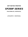
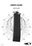
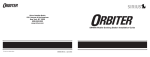
BSWA Technology Product Catalogue COMPANY OVERVIEW BSWA Established in 1998, BSWA Technology Co., Quality Ltd. is an acoustical company covering the businesses: - Developing acoustic measurement systems and devices BSWA is fully committed to Quality Management ensuring that every product meets strict standards in performance. BSWA continues to invest in new machine tool technology, new methods of calibration, and new process control methods to further microphone and related equipment technology while reducing manufacturing costs. - Designing and building anechoic chambers Research & Development - Acoustical consulting for environmental and noise control projects. As a technology-leading company, BSWA invests heavily in product research and development. BSWA hires skilled individuals, most with M.S. and Ph.D. degrees in Acoustics and related sciences. This results in not only an incredibly knowledgeable team of developers and technicians, but also a team that is dynamic, highly motivated, and able to develop and manufacture high quality products. - Manufacturing the world class measurement microphones With the headquarter located in Beijing, BSWA currently employed 55 staff with offices in Shanghai, Guangzhou and Chengdu. The BSWA’s products are distributed in more than 20 countries through our sales partners. Production BSWA's production facility is located 30 km from central Beijing and includes over 1200 m2 of floor space. The facility comprises manufacturing areas, test laboratories, environmental chambers, a full anechoic chamber, and a clean room. All microphones are hand built to and individually tested to meet BSWA's high standards in quality and performance. BSWA is continuously improving its products while developing new ones in response to customer needs. From 1998 till today, BSWA has launched such new products as Microphones Array, VA-Lab software, Impedance Tube, and a complete line of microphone products. BSWA strives for excellence in product design resulting in high quality, exceptional performance, and low cost. The latest information about BSWA can be found in: www.bswa-tech.com Launched VA-Lab measurement software -2007 Expanded microphone product line, launched MP series - 2004 2007 Acquired microphone business from IOA. - 2002 Established by five acoustic engineers partnered with Institute of Acoustics - 1998 Launched MP201 measurement microphones - 2000 Launched impedance tube measurement system-2005 First InterNoise Show in Korea -2003 Built anechoic chamber for Lenovo Computers -2001 1998 Acoustic projects appliance -1999 consulting for home companies 0 TABLE OF CONTENTS CONTENTS PAGE # Microphones 1/2'' Free Field Microphone Capsule-Class 1…………………….. 1/2'' Free Field Microphone Capsule-Class 2…………………….. 1/2'' Low Cost Microphone Capsule-Class 2……………………… 1/4'' Free Field Microphone Capsule………………………………. 1/2'' Pressure Field Microphone Capsule…………………………. Microphone Preamplifier…………………………………………….. 1/2''TEDS Microphones……………………………………………… 1/4''TEDS Microphones……………………………………………… ICP Sound Intensity Probe………………………………………….. Studio Microphone…………………………………………………… Microphones Array…………………………………………………… Microphone Spherical Surface Fixture…………………………….. Microphone Conditioning Units…………………………………….. Electrostatic Actuator & Power/Calibrator………………………… 2 3 4 5 6 7 8 9 10 11 12 13 14 15 Measurement Hardware Data Acquisition Hardware…………………………………………. Artificial Ear & Artiricial Mouth……………………………………… Omni-Sound Source & Power Amplifier…………………………… Mid-frequency Volume Source…………………………………….. Tapping Machine…………………………………………………….. Impedance Tube…………………………………………………….. Anechoic Box………………………………………………………… 16 17 18 19 20 21 22 Measurement Software - VA-Lab VA-Lab Software Overview…………………………………………. Architectural and Environmental Modules………………………… Sound Power and Sound Intensity Modules……………………… Impendance Tube Module………………………………………….. Audio Analyzer Module……………………………………………… 23 24 25 26 27 Accessories………………………………………………………….. 28 1 1/2’’ FREE FIELD MICROPHONE CAPSULE- CLASS 1 MP201 The MP201 microphone is the best choice for use in IEC61672 Class 1 Sound Level Meters and other noise measurements requiring Class 1 accuracy. It is a 1/2" prepolarized free-field measurement microphone whose development spans over 30 years in design, manufacture, calibration, and field testing. Handcrafted to exacting standards along with rigorous testing ensure its high quality, reliability, and extreme stability in all kinds of environments. Its incredible performance stems from its nickel alloy diaphragm using BSWA's diaphragm coating technology. The microphone housing is also made from the same nickel alloy to ensure the smallest temperature coefficients. Production quality control for the MP201 uses only 40% of the frequency response tolerances allowed by IEC61672 Class 1 microphones! Figure below shows the typical free-field frequency response curve of the MP201 (black curve) against quality control limits (red curves). Each microphone is supplied with its individual calibration data for frequency response and sensitivity. Its stability and versatility has been proven in all fields of acoustic measurements. It's no wonder many world-leading manufacturers of Class 1 sound level meters choose the MP201 microphone. Its proven quality, reliability, stability, and performance simply make it the best choice. SPECIFICATIONS MICROPHONE MP201 Diameter 1/2 inch Response Free Field Open-Circuit Sensitivity -26 dB±2 dB (50 mV/Pa) Frequency Response 20 Hz ~ 20 kHz Polarization Voltage 0V Dynamic Range (3% Distortion Limit) Cartridge Thermal Noise > 146 dB < 16 dBA Capacitance (Typical) 16 pF Pressure Vent Rear Vented Equalization Operating Temperature -30°C ~ 80°C Operating Humidity 0 ~ 98% RH Equivalent Air Volume 250 mm3 at 250 Hz Temperature Coefficient (-10°C ~ 50°C) - 0.005 dB/°C Humidity Coefficient -0.003 dB/%RH Pressure (250 Hz) -0.004 dB/kPa Coefficient Dimensions IEC 61094-4 Type WS 2 4 3 2 1 dB 0 -1 -2 -3 -4 -5 -6 10 100 1000 10000 100000 Frequency (Hz) Typical Free-field Frequency Response Curse of MP201 2 1/2’’ FREE FIELD MICROPHONE CAPSULE - CLASS 2 MP215 SPECIFICATIONS MICROPHONE MP215 The MP215 microphone is a 1/2" prepolarized free-field measurement microphone and the best choice for use in IEC61672 Class 2 Sound Level Meters and other noise measurements requiring Class 2 accuracy. The design of the MP215 is based on the high performance MP201 design and technology. Like MP201, the microphone diaphragm of MP215 is also made from a nickel alloy using BSWA diaphragm coating technology while the housing is made from stainless steel. The temperature, pressure, and humidity coefficients are better than IEC 61672 Class 2 requirements. To help distinguish it from the MP201, the microphone protection grid of MP215 was redesigned. The figure below illustrates the typical polar pattern of MP215 and its exceptional omni-directional capability. Each microphone is individually calibrated using an electrostatic actuator and pistonphone and all microphones are environmentally aged for long-term stability. The MP215 is an excellent all around Class 2 microphone with proven design for quality, reliability, stability, and performance. 2.5 kHz Diameter 1/2 inch Response Free-field Open Circuit Sensitivity -28 dB±3 dB (40 mV/Pa) Frequency Response 20 Hz ~ 12.5 kHz Polarization Voltage 0V Dynamic Range (3% Distortion Limit) > 146 dB Cartridge Thermal Noise < 25 dB (A) Capacitance (Typical) 13 pF Pressure Vent Rear Equalization Operating Temperature -20°C~ 80°C. Operating Humidity 0 ~ 98% RH Equivalent Air Volume 240 mm3 at 250 Hz Temperature Coefficient 0°C ~ 40°C <±0.6 dB at 250 Hz, at reference temperature 23 °C Humidity Coefficient 20% - 90% RH <±0.6 dB at 250 Hz at temperature 40°C, and reference 50% RH Pressure Coefficient 85 kPa ~ 108 kPa: SPL change < ±0.6 dB at 250 Hz at reference pressure 101 kPa. 65 kPa ~ 85 kPa: SPL change < ±1.2 dB at 250 Hz Dimensions IEC 61094-4 Type WS 2 5 kHz 10 kHz Directional Response of MP215 Microphone. 3 1/2’’ LOW COST MICROPHONE CAPSULE- CLASS 2 MP216 SPECIFICATIONS MICROPHONE MP216 The MP216 is a 1/2" prepolarized free-field condenser microphone. Developed specifically as an extremely low cost, general purpose microphone, it delivers Class 2 measurement accuracy. MP216 uses a polymer diaphragm and stainless steel housing making it well suited for use indoors and in controlled environments. These materials and associated manufacturing significantly reduce its cost but also limit its ability to meet Class 2 temperature and pressure coefficients. The overall stability and reliability within a constant environment, however, is maintained and ensured through testing of each microphone. The MP216 protection grid is irremovable and the calibration of the microphone is performed in the anechoic chamber. The microphone is supplied with its individual sensitivity and typical MP216 frequency response curve, as shown in the figure below. As an option, the actual frequency response of the microphone can be supplied. Diameter 1/2 inch Response Free Field Open-Circuit Sensitivity (250 Hz) -30 dB±3 dB (32 mV/Pa) Frequency Response 20 Hz ~ 16 kHz; Polarization Voltage 0V Dynamic Range (-3% Distortion Limit) > 135 dB Cartridge Noise < 25 dBA Thermal Capacitor (Typical) 20 ~ 30 pF Pressure Vent Rear Vented Equalization Operating Temperature 0°C ~ 40°C Operating Humidity: 0 ~ 98% RH Equivalent Air Volume 280 mm3 at 250 Hz Temperature Coefficient (250 Hz) Humidity Coefficient (250 Hz) Pressure (250 Hz) Dimensions Coefficient 0.05 dB/°C 0.02 dB/%RH 0.05 dB/kPa IEC 61094-4 Type WS 2 2 0 dB -2 -4 -6 -8 -10 10 100 1000 10000 100000 Frequency (Hz) Typical Free-field Frequency Response Curve of MP216 4 1/4’’ FREE FIELD MICROPHONE CAPSULES MP418 MP205/MK401 MP418 MK401 The MK401 is 1/4" free-field microphone required a polarization voltage of 200 V. The frequency range of MK401 is from 20 Hz to 70 kHz and meets IEC 61672 Class 1 requirements. The dynamic range of MK401 is up to 170 dB, which makes MK401 the best choice for high intensity and top loudspeaker testing. The MP418 is a 1/4" free-field prepolarized microphone. It was developed based on BSWA's Type 1 microphone technologies. MP418’s frequency response meets IEC61672 Class 2 requirements. Each microphone is individually calibrated and aged at 80°C for long-term stability and reliability. MK401 can be used with BSWA MV201 preamplifier and MC701 Power Supply. SPECIFICATIONS SPECIFICATIONS CLASS 2 MICROPHONE MP418 Diameter 7 mm (∼1/4”) Response Free Field Diameter 7mm (∼1/4”) Open-Circuit Sensitivity -40 dB±3 dB (10 mV/Pa) Response Free Field Frequency Response 20 Hz ~ 16 kHz Open-Circuit Sensitivity -60 dB±3 dB (1 mV/Pa) Polarization Voltage 0V Frequency Response 20 Hz ~ 70 kHz Polarization Voltage 200 V Dynamic Range (3% Distortion Limit) Cartridge Thermal Noise > 137 dB Dynamic Range (3% Distortion Limit) Cartridge Thermal Noise < 36 dBA Capacitance (Typical) 6 pF Pressure Vent Front Vented Equalization CLASS 1 MICROPHONE MK401 > 170 dB < 45 dBA Capacitance (Typical) 6 pF Front Vented Operating Temperature 0°C ~ 40°C Pressure Vent Equalization Operating Humidity 0 ~ 98% RH Operating Temperature -20°C ~ 80°C Dimensions Length: 8.5 mm, Thread Size: M6 x 0.5 Operating Humidity 0 ~ 98% RH Dimensions Length: 8.5 mm, IEC 61094-4 WS3F 1 0 0 0 2 0 5 0 1 0 0 2 0 0 5 0 0 1 0 0 0 2 0 0 0 5 0 0 0 1 0 0 0 0 2 0 0 0 0 4 0 0 0 0 6 0 0 0 0 Typical Free-field Frequency Response Curve of MK401 5 1/2'' PRESSURE FIELD MICROPOHONE CAPSULES MP251/253 There are three types of sound field measurement microphones for use in different testing environments: free-field microphone, pressure-field microphone, and random-incidence microphone. When making a measurement at frequencies below 5000Hz, the differences of the measurements using the above three types of microphones are within 0.3 dB. The measurement difference could be higher than 10 dB at the high frequencies above 16 kHz. Therefore, choosing the right microphone is a must for making accurate measurements. - Random-incidence Microphone: Only USA standard has requests for random-incidence microphones. So to make the measurement conform to the USA ANSI standard, a random-incidence microphone is required. - Free-field Microphone: A microphone can change the sound field in which it is placed. A free-field microphone is designed to compensate for the influence of its presence in the sound field. So it can measure the sound pressure as it existed before the microphone was introduced into the sound field and can be used in such environments as outdoors, anechoic room, or reverberation room. - Pressure-field Microphone: a pressure-field microphone can measure the sound pressure existing on the diaphragm of the microphone. It can be used in a coupler environment such as an ear simulator or to test the sound pressure on a surface. The MP251 and MP253 are 1/2’’ pressure-field microphones and designed to make the measurement in an ear simulator, a coupler or the sound pressure on a surface. SPECIFICATIONS MICROPOHONES MP251/MP253 Models MP251 MP253 Diameter 1/2 inch 1/2 inch Pressure-field Pressure-field -40 dB±2 dB (10 mV/Pa) -26 dB±2 dB (50 mV/Pa) 20 Hz ~ 20 kHz 20 Hz ~ 10 kHz 0V 0V > 146 dB > 146 dB < 25 dBA < 25 dBA 16 pF 16 pF Pressure Equalization Vent Rear Vented Rear Vented Operating Temperature -30°C ~ 80°C -30°C ~ 80°C Operating Humidity 0 ~ 98% RH 0 ~ 98% RH Sound Field Open-Circuit Sensitivity Frequency Response Polarization Voltage Dynamic Range (3% Distortion Limit) Cartridge Thermal Noise Capacitance (Typical) Equivalent Air Volume Temperature Coefficient (-10°C ~ 50°C) Humidity Coefficient Pressure Coefficient (250 Hz) Dimensions 3 250 mm at 250 Hz 250 mm3 at 250 Hz - 0.008 dB/°C - 0.008 dB/°C -0.006 dB/%RH -0.006 dB/%RH -0.005 dB/kPa -0.005 dB/kPa IEC 61094-4 Type WS 2P IEC 61094-4 Type WS 2P 6 MICROPHONE PREAMPLIFIERS MA211/MA408/MV201 MA211 MA408 The MA211 is 1/2’’ ICP preamplifier specially designed for BSWA 1/2" prepolarized microphones. It is high performance preamplifier with low inherent noise and high input impedance. Its flat frequency response ensures high quality acoustic measurements that comply with IEC 61672 Class 1 requirements. The MA408 is 1/4’’ preamplifier using SMB connector for the output while the threads for the microphone comply with the IEC61094-4 WSF3 standard. This makes it suitable for use with any standard prepolarized 1/4" microphone. MV201 Compared with traditional microphone preamplifiers, ICP types are lower in cost, easy to use, and able to connect directly to any ICP input channels and transmit signals over long cable lengths (up to 500 m). Coupling the MA211 with BSWA MP201 microphone, an incredible dynamic range of 15 dBA to 130 dBA can be achieved. If coupled with a lower sensitivity microphone, an upper range even greater than 130 dBA can be achieved. SPECIFICATIONS The MV201 is 1/2’’ traditional preamplifier with an integrated 3 meter cable terminating in 7-pin LEMO connector. MV201 can deliver 200V for externally-polarized microphones. It is suitable for accurate measurement of high sound intensity. It can be powered by BSWA MC701 microphone power supply. MICROPHONE PREAMPLIFIER MA211/MA408/MV201 Models MA211 MA408 MV201 Diameter 1/2 inch 1/4 inch 1/2 inch Frequency Response (Ref: 250 Hz, ±0.2 dB) 20 Hz ~ 100 kHz 20 Hz ~ 100 kHz 5 Hz ~ 200 kHz Attenuation (10 Hz ~ 100 kHz) < 0.5 dB < 0.5 dB < 0.5 dB Input Impedance > 5 GΩ > 1.5 GΩ > 20 GΩ Output Impedance < 110 Ω < 110 Ω < 55 Ω A-weighting < 2.0 μV 20 Hz ~ 20 kHz < 6.0 μV A-weighting < 2.5 μV 20 Hz ~ 20 kHz < 8.0 μV A-weighting < 3.0 μV 20 Hz ~ 20 kHz < 6.0 μV Max Output Voltage 3.5 Vrms 3.5 Vrms 10 Vrms Power Requirement ICP (2 ~ 20 mA) ICP (2 ~ 20 mA) 28 V, 120 V Operating Temperature -20°C ~ 80°C -20°C ~ 80°C -20°C ~ 80°C Operating Humidity 0 ~ 98% RH 0 ~ 98% RH 0 ~ 98% RH 71 mm 58 mm 71 mm BNC SMB 7-pin LEMO Φ11.7 mm x 60 UNS Φ5.7 mm x 60 UNS Φ11.7 mm x 60 UNS Electrical Noise Length Output Connector Thread for Microphone 7 1/2'' ICP TEDS MICROPHONES MPA201/205/206 & MPA261/265/266(TEDS) MPA215 MPA215 provides excellent value, with good environmental stability and phase-matching ability. It is the best choice where a large number of microphones require Class 2 accuracy. MPA216 BSWA ICP microphones, MPA201/215/216, utilize the outstanding performance of BSWA's MA211 ICP preamplifier coupled with the high quality line of 1/2" prepolarized microphones. Using ICP microphones have many advantages over traditional 200V polarized microphones. - ICP microphones are lower cost. - They are able to use long cable lengths, up to 500 meters. - They work with any ICP input channel, which can be used for both acoustic and vibration measurements. MPA201 MPA201 offers BSWA's top of the line choice and is suitable for all acoustical measurements requiring Class 1 accuracy. The MPA201 is extremely stable environmentally. It is widely used in multi-channel sound measurements including acoustic arrays due to its excellent phase-matching and sensitivity characteristics. MPA216 is BSWA's extremely low cost solution while still delivering accurate acoustic measurements. The MPA206 is recommended for indoor uses, where temperature and humidity are relatively stable over the measurement time period. TEDS Microphones TEDS stands for the Transducer Electronic Data Sheet defined in IEEE 1451.4 standard. The MPA261/265/266 are ICP TEDS microphones. They are the combination of BSWA 1/2’’ microphones and TEDS preamplifier MA211. The TEDS microphone will include such information as the microphone model, serial number, sensitivity, reference frequency, calibration date, and etc. The TEDS information will be read by an ever-increasing range of instruments. The TEDS microphone helps to facilitate plug and play and reduce the setup time of the system. The MPA series of TEDS microphones are sealed to the preamplifier with a calibration sticker. SPECIFICATIONS ICP MICROPHONES MPA201/215/216 and TEDS ICP MICROPHONE MPA261/265/266 Models Microphone Capsule Diameter Preamplifier Optimized Frequency Response Sensitivity Max. SPL for 3% THD Equivalent Noise Level Output Impedance Max. Output Voltage Connector ICP Power MPA201/MPA261 MP201 20 Hz ~ 20 kHz 50 mV/Pa 130 dB 18 dBA MPA215/MPA265 MP215 1/2 inch MA211/MA211 with TEDS 20 Hz ~ 12.5 kHz 40 mV/Pa 132 dB 25 dBA 110 ohms 4.5 Vrms BNC Current 4.0 mA MPA216/MPA266 MP216 20 Hz ~ 16 kHz 32 mV/Pa 132 dB 24 dBA 8 1/4 ” ICP TEDS MICROPHONES MPA416/MPA466 MPA416 SPECIFICATIONS The MPA416 is 1/4” prepolarized free-field measurement microphone. It is an ideal choice for array applications where a large number of microphones are required. ICP MICROPHONE MPA416/466 (TEDS) MPA416 features: - High Sensitivity: 50 mV/Pa. This is a high sensitivity for 1/4” microphones. The advantage of such high sensitivity is to provide high signal output to data acquisition board. - Low Noise Floor: 29 dBA. MPA416 is tested to have noise floor of 29 dBA. It can be used to measure noise from computers, home appliances and other low noise machines. - Flat Frequency Response: 20 Hz ~ 20 kHz. The frequency response complies with IEC 61672 Class 1 tolerances. - Phase Match: Special attentions are paid to phase-match; MPA416 has the guaranteed phase- match tolerances. Response Free-field Sensitivity -26 dB±2 dB (ref 1V/Pa) ; or 50mV/Pa. Equivalent Noise Level 29 dB(A) Upper Dynamic Limit 127 dB Frequency Range 20 Hz ~ 20 kHz (complied with IEC 61672 Class 1 requirements at reference conditions) Power supplier ICP T.H.D < 3% at 128 dB SPL Temperature Coefficient:(at 1000 Hz, at reference temperature 23°C) 15 ~ 35°C: <±0.3 dB 0 ~ 40°C : <±1.5 dB -10 ~ 50 °C:<±3.0 dB Humidity Coefficient The main applications of MPA416 may include: Operating Temperature Range - Microphone array Polarization Voltage: - General acoustical measurements at controlled environments (in rooms or laboratories) MPA466 The MPA466 is the TEDS version of 1/4” prepolarized free-field measurement microphone which has the information of microphone model, serial number, sensitivity, reference frequency, calibration date, and other information to facilitate plug and play and reduce the setup time of the testing system. -10°C~50°C 0V 4 2 0 -2 dB MPA416 consists of an electret condenser microphone cartridge and ICP preamplifier (irremovable). Before factory release, all the microphones are going through solid environmental testing, which includes high temperature ageing and high humidity ageing. It is stable microphone for accuracy acoustical measurements. 20%~90% RH ; Sound Pressure Level Change < ±0.8 dB at 1000Hz at temperature 30°C, and reference 50% RH -4 -6 -8 -10 10 100 1000 10000 Frequency (Hz) Typical Frequency Response of MPA416/MPA466 9 100000 ICP SOUND INTENSITY PROBE SI 502 T he SI502 Sound Intensity Probe is built using ICP type preamplifiers. It complies with IEC 1043 Class 2 Standard. Based on the technique of simultaneous determination of sound pressure and particle velocity by two closely spaced microphones, SI502 can be directly connected to ICP inputs to perform sound intensity measurements. Features - ICP® powered Two BNC connectors for easy connection Accurate phase matched microphones Face to face configuration 1/3-octave centre frequency ranges: 63 Hz to 5 kHz Well-defined acoustical microphone separation. The SI502 is constructed on a face-to-face design. It comprises a robust frame which holds two ICP preamplifiers and matched microphones in a face-to-face configuration. The distance between microphones is defined by solid, plastic spacers. Sound is constrained to act on each microphone through a narrow slit between the spacer and the microphone grid. This gives well-defined acoustic separation of the microphones and minimizes shadow and reflection effects. SPECIFICATIONS SOUND INTENSITY PROBE SI502 Standard IEC 1043 Class 2 Frequency Range (1/3 Octave) 8.5 mm Spacer: 250 Hz ~ 5000 Hz 12 mm Spacer: 160 Hz ~ 5000 Hz 50 mm Spacer: 63 Hz ~ 1250 Hz Weight 0.4 Kg Phase matching of 1/2″Microphone Pair selected from Type MP201 is better than 2 degrees in full test frequency range from 45 Hz to 6000 Hz. The normalized microphone frequency responses differ by less than 0.5 dB. SI502 is supplied with 8.5 mm, 12 mm and 50 mm spacers. Output Connectors Three-pin Lemo in the Probe Cable to ICP inputs 5 m cable with Lemo to 2 BNC connectors Case Dimensions 400 x 200 x 70 mm Each probe is individually calibrated in the anechoic chamber; the calibration data include phase matching, microphone sensitivities and actuator responses. Microphones Selected Type 1 MP201 for intensity microphone pair Diameter 1/2 inch Response Free Field Combined Sensitivity 45 mV/Pa Microphone Phase Response Difference <0.3º, 45 Hz ~ 500 Hz <1º, 500 Hz ~ 2500 Hz <2º, 2500 Hz ~ 6000 Hz Amplitude Response Difference (Ref 250 Hz) < 0.5 dB ; 45 Hz ~ 6000 Hz Equivalent Air Volume 250 mm3 at 250 Hz Temperature Coefficient (-10 ~ 50°C) -0.005 dB/°C Humidity Coefficient -0.003 dB/%RH Pressure (250 Hz) -0.004 dB/kPa MICROPHONE PAIRS Coefficient Dimensions IEC61094-4 Type WS 2 Preamplifier BSWA Type MA211 preamplifier 10 STUDIO MICROPHONES SM4001/SM4005/SM4006 T he SM4000 series phantom powered studio microphones are for precision recording and measurement of sound with no color added. They can be used to record essentially any instrument for a truly accurate representation of the original sound. Each SM4000 microphone is supplied with its individual calibration data for frequency response and sensitivity. Its modular design allows the preamplifier to be used with any of the high quality BSWA microphone capsules. SM4001 microphone is top of the line. It is suitable for the most critical recording applications requiring extreme performance and environmental stability. Its nickel alloy construction ensures durability and outstanding performance. The electronic circuitry coupled with a transformerless output stage provides a flat frequency response across the entire audio bandwidth while at the same time achieving an extremely low noise floor. With a dynamic range of 125 dB handling up to 146 dB SPL, it is a handcrafted work of art. SM4006 microphone offers an economical choice with incredible performance. Its polymer diaphragm and copper housing yields a flat frequency response out to 16 kHz with excellent dynamic range and low noise floor. It is a proven performer for the price. SM4005 microphone is a top performer that uses the same preamplifier as the SM4001. It has the same flat frequency response out to 16 kHz stemming from its nickel alloy diaphragm. It is a great choice for accurate acoustic recording requiring a large dynamic range. SPECIFICATIONS STUDIO MICROPHONES SM4000 SERIES Models SM4001 SM4005 SM4006 Microphone Capsule MP201 MP215 MP216 20 Hz ~ 20 kHz 20 Hz ~ 12.5 kHz 20 Hz ~ 16 kHz 50 mV/Pa 40 mV/Pa 32 mV/Pa Max. SPL for 3% THD 146 dB 140 dB 130 dB Equivalent Noise Level 18 dBA 25 dBA 24 dBA Linear Frequency Range Sensitivity Output Impedance Max. Output Voltage 200 Ω 4.5 Vrms (load > 2000 Ω); 1.0 Vrms (load =1000 Ω) Connector Phantom Power XLR 25 V ~ 48 V (current 3 mA) Weight Polar Pattern 160 g Omni Directional MODULAR PARTS SMA4000P Phantom Powered Preamplifier for SM4000 Series Microphones SM4000 K Microphone Kit includes SMA 4000P, MP201, MP215, and MP216 11 MICROPHNE ARRAYS SPT980/SPS980/SPS490 BSWA designs and manufactures microphone arrays for acoustical measurements. Our experience spans from simple linear array to complicated random array. The number of microphones in the arrays ranges from 16 to 256 according to the customers’ requirements. Microphones are the most important elements in the array; BSWA uses MPA416 (or MPA466 with TEDS) for 1/4” microphone array. The phases of the microphones are matched according to the customer’s specifications. For critical applications where high accuracy and low noise are required, BSWA will recommend MPA201 (or MPA261 with TEDS) as microphone elements To make the array structurally stable, BSWA uses stainless steel (or aluminum) and CNC cutting to fabricate the mechanical parts. SPS490 Spiral Array SPS980 Spiral Array Customized Cross Array SPECIFICATIONS MICROPHONE ARRAY SPT980/SPS980/SPS490 Model Type of Array No. of Microphones Diameter Microphone Model Dynamic Range Frequency Range Phase Match Cabling SPT980 SPS980 SPS490 Spiral Spiral Spiral 36 36 16 1.0 m 1.0 m 0.5 m MPA201T MPA416 MPA416 20 ~ 135 dBA 30 ~ 128 dBA 30 ~ 128 dBA 20 Hz ~ 20 kHz 20 Hz ~ 20 kHz 20 Hz ~ 20 kHz ±2 º ±5 º ±5 º 8-pin LEMO to 8 SMBs 8-pin LEMO to 8 SMBs 8-pin LEMO to 8 SMBs 12 MICROPHONE SPHERICAL SURFACE FIXTURE MF720/MF710 In the measurement of sound power level according to ISO 3745-2003, 20 measurement positions are required on a spherical measurement surface enveloping a noise source in anechoic and hemi-anechoic room. However, it is difficult to mount 20 microphones on tripods in a spherical surface. BSWA Technology developed MF720 (and MF710) microphone fixture specifically for such measurements. MF720 is designed according to ISO 3745-2003 to mount 20 microphones over the spherical surface; MF710 is a 10 positions version according to ISO3745; ISO7779 and GB6882. MF720/ MF710 main features: - 20 / 10 microphone positions - The position and orientation of each microphone can be adjusted to fit the amendment of the ISO standards - Portable with light weight and the parts can be disassembled for easy transportation Microphone Mounting for MF710 Microphone positions for MF720 SPECIFICATIONS MICROPHONE SPHERICAL SURFACE FIXTURE MF710/MF720 Model No. of Microphone Positions Standards Radius (microphone positions) (m) Microphone Size to be Fixed on (inch) Carrying Case (mm) Weights(kg) MPA201 1/2” ICP Microphones CBB 020 20 m BNC cables MF720 20 ISO3745-2003 1.0 1/2 1500 * 350 * 200 11 OPTIONAL ITEMS 20 20 MF710 10 ISO7779;GB6882-88; ISO3475-1982 1.0 1/2 1500 * 350 * 200 10 10 10 13 MICROPHONE CONDITIONING UNITS MC102/MC104/MC701 MP205 MC102 MC102 is a 2-channel ICP power supply that provides a constant 4.0 mA current to ICP microphones and other ICP sensors. The output signals from MC102 can be connected directly to other equipment or data acquisition systems with BNC connectors. To reduce line noise and increase portability, the MC102 is battery powered and includes a built-in low battery indicator. MC701 MC701 microphone conditioning can supply microphone with 200V polarization voltage. The input of MC701 is 7-Pin LEMO while the output is BNC connector. The MC701 has selection of polarization voltage of 0, 28 and 200 V. It can be used with MV201 preamplifier and BSWA MP and MK series microphones The gain of MC701 can be adjusted to -20 dB, 0 dB, and +20 dB and the frequency range is between 5 Hz and 200 kHz. MC104 MC104 is a 4-channel microphone conditioning. It can supply 4.0 mA current to ICP microphones and other ICP sensors. Each channel has a gain of ×0.1, ×1, and ×10. MC701 can be powered by 110/220 VAC and is suitable for laboratory use. SPECIFICATIONS MICROPHONES CONDITIONING MC701 MC104 can be powered by 110/220 V AC. SPECIFICATIONS Number of Channels 1 Polarization Voltage 220 V, 28 V, 0 V Power Supply 220 V/110 V AC Frequency Range 5 Hz ~200 kHz Gain -20 dB, 0 dB, 20 dB Input Connector 7-Pin LEMO Output Connector BNC Dimensions 200x100x150 mm ICP POWER SUPPLY MC102/MC104 Model MC102 MC104 2 4 4.0 mA 4.0 mA 1x 9 V (PP3) 220 V/110 V AC - ×0.1, ×1, and ×10 Input Connector BNC BNC Output Connector BNC BNC Battery Life > 4 hrs - Dimensions 113 x 70 x 45 mm 310 x 250 x 65 mm Number of Channels Constant Current Battery Gain 14 ELECTROSTIC ACTUATOR&POWER/CALIBRATOR EA002/AS002/CA106 EA002 Electrostatic actuator is used for testing frequency response of microphones. An electrostatic actuator comprises an electric metal plate which can be placed near the microphone diaphragm. A time-various voltage is applied in between the metal plate and the diaphragm and thus an electrostatic force simulating sound pressure can be distributed on the diaphragm surface. BSWA electrostatic actuator EA002 is especially designed for testing the frequency response of 1/2’’ microphones. It can be used to calibrate the sound level meters according to IEC61672-3 Standard. The EA002 conforms to IEC 61094-6 standard and can be calibrated periodically with a sound level meter in accordance with IEC 61672-3 standard. AS002 CA106 The CA106 Sound Level Calibrator is a pocket-sized, battery operated sound source for quick and direct calibration of sound level meters and other sound measuring systems. The CA106 satisfies the IEC60942 Class 2 standard and fits all 1/4", 1/2" and 1" diameter microphones. The CA106 provides a continuous sound pressure level of 94.0 dB at 1 kHz allowing the same calibration value to be used for all weightings. After one minute running, the CA106 automatically turns off conserving battery power. SPECIFICATIONS CALIBRATOR CA106 An 800V DC bias voltage is needed for driving electrostatic actuator. The AS002 is the electrostatic actuator power supply. It have built-in signal amplifier of 30 dB. It can take the signal directly from a data acquisition card. SPECIFICATIONS ELECTROSTATIC ACTURTOR EA002 Standards IEC 61094-6 Microphone Diameter 1/2’’ Dimension Φ50 x 30 mm Weight 150 g ELECTROSTATIC ACTURTOR POWER AS002 Standards IEC 60942 (2003) Class 2 Calibration Level 94 dB±0.4 dB Calibration Frequency 1 kHz±1.7% Harmonic Distortion < 2.5% Environmental Influences (reference to standard conditions) SPL < ±0.4 dB; Freq < ±1.7% Temperature: 0 ~ 40 ℃ Humidity: 20 ~ 90 % Pressure: 65 ~ 108 kPa Stabilization Time 30 s Coupler Volume > 150 cm³ Battery 1 x 9 V (PP3) Battery Life Alkaline manganese is recommended with a battery life better than 24 hours Max. Input Signal 1 Vrms Signal Magnified by 30 dB Max. Output Signal 25 Vrms DC Bias Voltage 800 V Frequency Range 1 Hz ~ 200 kHz Dimensions Φ41 x 102 mm Output Impedance 1500 Ω Weight 287 g (battery included) Power Supply 220 V 50 Hz Dimension 285 x200 x105 mm Weight 2.4 Kg 15 DATA ACQUISITION HARDWARE MC3022/MC3522/MC3242 MC3022 MC3522 The MC3522 is developed to meet the need of audio testing, where a small power amplifier is required to drive the loudspeakers. MC3522 has a built-in 20W power amplifier with a lockable knob. The MC3022 is a USB powered Plug-N-Play measurement soundcard with two ICP input channels and one output source channel. MC3022 is based on 16 bit A/D converters with two-channel simultaneous sampling frequency of 44.1 kHz. It is the perfect start to building your own two-channel sound and vibration measurement system. The MC3522 is USB powered for measurements. It required 220V when the power amplifier is switched on. MC3242 Based on sound card technology, MC3022 frequency response ranges from 20 Hz to 20 kHz with an accuracy of +0.5/-1.0 dB. Specially designed circuitry lowers the system noise floor by significantly reducing high frequency noise common in USB powered devices. The input channels can be connected to any ICP powered sensor and when using BSWA ICP microphones (MPA201/215/216), MC3022 is capable of measuring acoustic signals from an amazing 35 dBA to 118dBA without any change in signal gain. The output channel is capable of providing a 1.0 Vrms source signal to speakers, shakers, and other devices. The MC3022 is designed for VA-Lab acoustic measurement software developed by BSWA. It also works with a number of software including WinMLS, DIRAC, EASERA, Audio Tester, Listen, ETF, NoiseBook, SpectralPlus, and LabView, just to name a few. The MC3242 is a 4-channel hardware designed using NI 9233 data acquisition card. It can analyze acoustic and vibration signals acquired simultaneously from its 4 channels. MC3242 has two signal output channels. The MC3242 is designed for VA-Lab software. It can be used for sound transmission loss testing in BSWA impedance tubes. It can also be used in general acoustic or vibration measurements. SPECIFICATIONS DATA ACQUISITION HARDWARE MC3022/MC3522/MC3242 Model Input Channel Max Input Voltage Output Channel MC3022 1 Max Output Voltage Frequency Response Connector A/D Converter Max. Sampling Frequency Internal Noise Frequency Response (Ref: 250 Hz, + 0.5 dB/-1.0 dB) 2, ICP (4 mA) 1.0 Vrms 1, with 20 W power amplifier 1.0 Vrms IEC 61672 Type 2 BNC 16 bits 44.1 kHz 35 dBA MC3242 4, ICP (4 mA) ±5 V 2 ±1 V 20 Hz ~ 20 kHz 24 bits 50 kHz 30 dBA 20 Hz ~ 20 kHz Measurement Range (With MPA201) Power Requirement MC3522 35 ~ 118 dBA USB USB (220/110 V when power amplifier works) 30 ~ 130 dBA USB 16 ARTIFICIAL EAR AND ARTIFICIAL MOUTH AE002/AM002 AE002 AM002 BSWA AE002 is designed to simulate human ear to test what human can hear. AE002 conforms to IEC60318 and ITU-TP.57 Standard. It can be used in the audio test of telephone or cell phone. BSWA AM002 is a sound source that can simulate sound from human mouth. AE002 can be used with BSWA microphone. MS003 conforms to IEEE 269, 661 and ITU-T Rec standards. BSWA ARTICICIAL MOUTH AM002 Standard BSWA ARTICICIAL EAR AE002 Standard Microphone as Option Microphone Preamplifier as Option IEEE 60 318, ITU-T Rec. P57 MP251 Pressure Field Microphone MA211 ICP Level at MRP IEEE 269, IEEE 661 and ITU-T Rec. P51 94 dB (200 Hz - 8000 Hz) Mouth Opening 20 mm diameter Loudspeaker 8 ohm/20 W Lip Ring External Diameter 40 mm Lip Ring Distance from Mouth 10 mm Test Parameters Refer to MP251/MA211 Diameter 40 mm Diameter 100 mm Height 120 mm Height 98 mm Weight 1.2 kg Weight 1.1 kg 17 OMNI-SOUND SOURCE& POWER AMPLIFIERS OS002/ SWA100/PA50 SWA100 The OS002 Omni Sound Source and SWA100 Power Amplifier are an ideal match for frequency response measurements, including Acoustic Reciprocity and Maximum Length Sequence (MLS) method. OS002 The SWA100 Power Amplifier produces an amazing 100W per channel at 8 Ωfor its incredibly compact size and low weight. It has the same features and protection circuits normally found only in more expensive, larger, and heavier amplifiers. Its two channels can be used independently of each other and uses BNC connectors for input signals. The SWA100 is specially designed to use passive cooling removing the need (and noise) of a cooling fan The OS002 Omni Sound Source uses 12 matched loudspeakers in a dodecahedral configuration. This achieves a spherical distribution pattern satisfying ISO 140-3 and ISO 3382 requirements. When connected to the SWA100 Power Amplifier, the OS002 can deliver the remarkable output power of 115 dB. All 12 specially selected speakers are connected in a series-parallel network to ensure both in-phase operation and matching impedance to the SWA100 Power Amplifier. The speaker enclosure is all metal providing a rugged, solid construction resulting in high acoustic performance. The OS002 is compact and less than 12" (30 cm) in diameter. With its high output power, it's an ideal choice for sound insulation, acoustic reciprocity, and many other sound source measurements. PA50 SPECIFICATIONS OMNI-SOUND SOURCE OS002 Standards ISO130-3; DIN52210 Nominal Impedance 6Ω Power Handling 200 W continuous Frequency Range 125 Hz ~ 4 kHz Sound Power Level 115 dB Pink Noise Connector Audio Connector Loudspeaker Units 4” Diameter; 8 Ω; 25 W Diameter 300 mm Weight 10 Kg Carrying Dimensions Case ISO3382; The PA50 is a single-channel power amplifier with a power at 50W. Designed to be light weighted, PA50 is equipped with protection circuit that other power amplifiers of higher price have. The PA50 is ideal unit for impedance tube and audio testing. 320 x 320 x 320 mm POWER AMPLIFIER SWA100 Audio Power 100 W Power Supply 220 V/110 V Dimensions (including case) 495 x 430 x 150mm Weight 12 kg 18 MID-FREQUENCY VOLUME SOURCE VSS 210 The VSS210 Volume Source is a mid-frequency volume source. It is ideal acoustical source for reciprocity measurements and TPA analysis. VSS210 uses a power speaker driver to deliver up to 125 dB over the frequency range from 200 to 10,000 Hz. Two phase matched MPA416 microphones is installed at 2 cm apart in the outlet. The microphones provide the sound pressure and phase information for calculating the volume velocity radiated from the outlet. Frequency Response of VSS210 Measured at 5 cm from Outlet in the Anechoic Chamber SPECIFICATIONS VOLUME SOURCE VSS210 Standards NONE Nominal Impedance 8Ω Power Handling 100 W continuous Frequency Range 200 Hz ~ 10000 kHz Sound Power Level 120 dB Pink Noise Connector Audio Connector Loudspeaker Unit Compassion Diver Tube Diameter 30 mm Tube Length 3m Weight 5 Kg Carrying Dimensions Case 100 W 420 x 420 x 320 mm 19 TAPPING MACHINE TM002 SPECIFICATIONS TAPPING MACHINE TM 002 Standards ISO140, BS5821, ASTM492, EN 20140 Hammers Five in line, 100 mm between each hammer, single hammer weight 500±2.5% Impact Frequency Each hammer operates at 2Hz; tapping frequency for unit is 10±0.3Hz self-contained sound source for making footfall noise measurements to the latest international standards (ISO140, EN 20140, ASTM E492, GB J75-84, etc.) Impact Forces Equivalent free-fall hammers 40 mm Motor 220 V, 50 Hz AC Main, Or 110 V, 60 Hz AC Main Rating Power: 25 W Features The TM002 Tapping Machine is a rugged, GBJ75-84, height of Dimensions − Ergonomic case for ease transportation − Five 500 g hammers with 40 mm falling heights − 10 impacts per second − Solid aluminum base for stable operation − Reduced machine noise via belt drive − Long lasting industrial drive motor − No metal-to-metal moving parts resulting in less wear and smooth operation − Both 220V AC and 110V AC powered units available 465 ×245 ×280 mm Carrying Case 555 × 310 × 400mm Net Weight 22.5 kg (29.5 kg including the case) Power supply 110 V or 220 V AC Fuse P 1.5A Operating Temperature -10~50℃ Operating Humidity 0~98% RH TM 002 1 Principle of Operation Power Cable 1 (Please specify the power plus, UK, USA, Japan, Germany, Australia) The TM002 uses an industrial 25 watt AC motor turning five cams via a belt drive for quiet operation. The cams in turn lift the hammers which fall 40 mm to impact the solid and durable base plate at a rate of 5 impacts per second. The base is made from 3/16"(50 mm) solid aluminum making the unit very stable during operation. Carrying Case 1 User’s Manual 1 STANDARD ITEMS INCLUDED Maintenances Special consideration was given to all the moving parts of the unit. No metal to metal contact is allowed. Teflon washers and spacers are used to guide the hammers, reducing friction, wear, noise, and maintenance. 20 SW230/SW260/SW433/SW463 IMPEDANCE TUBES The SW series Impedance Tubes can accurately measure sound absorption coefficients and impedance according to standards described in ISO10534-2 (1998). They are based on the Transfer Function Method, which is much faster than the commonly used Standing Wave Ratio Method. The Transfer Function Method separates the incident and reflected energy from the measured transfer function, and then estimates the acoustic properties of the tested sample located at the end of the tube. The SW series Impedance Tubes are specially designed not only to work with the cut samples, but also for direct use in the field. The small size and durable aluminum construction make it easy to transport and be used for estimating the properties of walls, ceilings, installed building materials, road surfaces, different ground surfaces, interiors of vehicles, etc. BSWA offers the complete set of Impedance Tube system, which includes: the tubes, microphones; DAQ hardware and measurement software. BSWA 1/4’’ microphones MPA416, which have excellent phase matches, is ideal for impedance applications. The microphones are directly connected to optional 2-channel MC3022 or 4-channel MC3242 data acquisition hardware. The PA50 power amplifier is used to drive the 20W loud speaker in the impedance tube. The BSWA VA-Lab software provides all measurement functions for sound absorption and transmission loss testing. SW230/260 The SW230/260 Impedance Tubes are used to measure the sound absorption coefficients of materials. The measurement frequency ranges from 125 Hz to 6300 Hz. SW230/260 is designed to have two locations for 1/4" microphones needed for measuring sound pressures. SW433/463 SW433/463 Impedance Tubes are designed to measure both sound absorption coefficients and transmissions loss. The tube uses four 1/4" microphones for measuring sound pressures along the tubes. SPECIFICATIONS IMPEDANCE TUBE SW230/SW260/SW433/SW463 Model SW230 Value to be Measured Sound Absorption Coefficient (α) Standard SW260 125 Hz ~ 3150 Hz 125 Hz ~ 6300 Hz Loud speaker SW463 Sound Absorption Coefficient (α); Transmission Loss(TL) GB/T-18696, 2-2002, ISO10534-2, 1998 Frequency Range Inner Diameter Testing Tube SW433 Standard in Discussion 125 Hz ~ 3150 Hz (α) 125 Hz ~ 6300 Hz (α) 125 Hz ~ 3150 Hz (TL) 125 Hz ~ 3150 Hz (TL) 4 “ in diameter, 20 Watts, 8 Ohm of Weight 60 mm 60 mm for low frequency; 30 mm for high frequency 60 mm 60 mm and 30 mm for Absorption; 60 mm for TL 8 kg 10 kg 11 kg 13 kg OPTIONAL ITEMS PROVIDED BY BSWA 1/4’’ Microphone Data Acquisition Card MPA416 MC3022 or MC3522 Power Amplifier Software MC3242 PA50 VA-Lab2 Basic+ VA-Lab2 IMP VA-Lab4 Basic+ VA-Lab4 IMP 21 ANECHOIC TEST BOX XS Series BSWA Anechoic Test Box is designed for acoustic measurements in the noisy environments. The functions of 小the anechoic test box are: - Providing a free field condition for measurements - Effectively isolating the environmental noise BSWA has a number of years of experiences in designing and building the box for various industries. The main applications are: - Mobile phone acoustic testing in production lines - Audio components testing for quality control - Noise level measurements for computer parts - Noise testing for electrical parts in automotive The XS Series Anechoic Test Box is made from steel sandwich panels with sound absorption material as fillings. The internal surface is perforated to provide sound absorption, while the external metal panel provides the sound insulation. Optional Sonex sound absorption foam can be added to the internal surface to increase the total absorption. The Anechoic Test Box is non-standard product; it requires the understanding of the customers’ needs. BSWA will take the design considerations of power supply, cables, microphone fixture, and operation of the device under test. SPECIFICATIONS ACOUSTIC PROPERTIES OF METAL PANEL Frequency (Hz) 63 125 250 500 1K 2K 4K 8K STC/NRC TL (dB) Absorption Coefficients 27 30 0.94 32 1.19 41 1.11 50 1.06 59 1.03 67 1.03 71 1.04 45 The Anechoic Text Box is a low cost alternative to the anechoic chamber. The correction factors can be determined by comparison of the measurements in the chamber and box. The noise reduction of 30 dBA is achievable in normal factory environmental by BSWA metal panels. The customer design is available when the higher noise reduction is required. BSWA is capable of providing the testing system with the anechoic test box. The customized testing system is developed using National Instruments LabView with BSWA hardware. 22 VA-LAB SOFTWARE OVERVIEW VA-Lab VA-LAB is acoustical measurement software developed by BSWA. VA-Lab takes the advantage of computer power and performs all signal analysis within the computer. VA-Lab supports BSWA Data Acquisition Hardware and Microphones. It is affordable and easy to use acoustic measurement software. VA-Lab is developed based on the international standards and BSWA experiences in acoustics. These experiences span from environmental, architectural, industrial, and audio acoustical measurements. VA-LAB has module design with the special applications according to ISO standard requirements, such as Sound Power, Sound Insulation, and Impedance Measurements. The VA-Lab function modules include: - BASIC: FFT based signal analysis for vibration and acoustics - ENV: Sound pressure level and environment noise measurements - IMP: Two and four microphone methods for absorption and TL measurements in Impedance tube according to ISO10534 - SI: Sound intensity measurements - REV: Reverberation time measurements according to ISO3382 - TL: Sound Insulation measurements for building material according to ISO 140 - POWER: Sound Power according to ISO3745 Measurements - AUDIO: Audio testing by using stepped sweeping, frequency sweeping and multi-tones VA-Lab software works with MC3022, MC3522, MC3242 and NI Compact DAQ hardware. The MPA201 microphone is commonly used with the VA-Lab systems. Main Features of VA-Lab BASIC: - FFT Analysis: general signal analysis by FFT or CPS. Data can be captured and saved in real-time mode - 1/n Octave: general 1/n octave analysis for sound and vibration signals - Calibration: user selection of sound or vibration calibration - Data View: Time history data view with linked to spectral data - Record: Wave file or time series signal record and play back 23 ARCHITECTUAL / ENVIRONMENTAL MODULES VA-Lab ARCH / ENV Environment Module Architectural Module VA-Lab ARCH module provides reverberation time measurements and sound transmission loss measurements according to ISO standards. . VA-Lab ARCH uses the interrupted noise method to measure the reverberation time in 1/1 or 1/3 octave frequencies. It displays the decay curves. VA-Lab Arch measures the sound pressure level difference between rooms, automatically corrects the reverberation time effects and calculates the sound insulation index using curving fitting. VA-Lab ENV is a powerful sound level meter. It supports 10 channel sound pressure level measurements at 10 locations. Each channel can perform multi-task analysis such as statistical levels, 1/3 octave, and levels vs. time. VA-Lab ENV has built-in data logger function, it can continuous log the overall and spectral data into the memory. Used with MC 3022 and MPA215 microphones, VA-Lab ENV satisfies IEC 61672 Class II accuracy requirements. Main Features of VA-Lab ENV - Simultaneously measure SPL, RMS, MAX, MIN, PEAK, LEQ, SEL, L10, L50, and L90 - A,C,Lin weighting - Fast, Slow, Impulse - Continuous, Time limited optionally Main Features of VA-Lab ARCH - Spectral data logger associated time history - Quick and easy Reverberation measurements according to ISO 3382 Time - Measurement of sound difference between rooms level pressure - Reverberation time corrections - 1/1 or 1/3 octave Real-time display - Sound level analysis at user defined intervals - Long time monitoring of sound pressure levels, up to 5 hours - Automatically calculate TL, Rw, C, and Ctr - Built-in pink noise generator 24 SOUND POWER/INTENSITY MODULES VA-Lab POWER / SI Sound Power Module In order to determine the sound power level produced by the noise source, one method is measuring the sound pressure level on the measurement surface enveloping a noise source. Sound Intensity Module VA-Lab Power module is specially designed to satisfy sound power level test according to ISO3745. With NI Compact DAQ and BSWA microphones, the noise level can be tested simultaneously in 10 channels; the sound power level is calculated automatically based on the measurement surface area. With microphone conditioning unit MC104 (MC1010 is 10 channel version), the background noise can be below 20 dBA for some critical measurements. The measurement of Sound Intensity provides information of magnitude and direction of the sound field, which is used in a variety of applications such as the determination of sound power and the noise source localizations. VA-Lab SI module provides a simple system for sound intensity measurements. The system requires two-channel data acquisition hardware MC3022 and intensity probe SI502. The measurements of sound intensity become very easy task. Main Features of VA-Lab SI - SIL and SPL Real-time display in 1/1 or 1/3 Octave - A and linear weighting - Residual Index of Intensity and pressure - Support user-defined microphone sensitivity, microphones distance, and test integrated time Main Features of VA-Lab Power - 10 Channel Sound pressure measurements simultaneously level - Sound Power Level calculation based on ISO3745 with environmental corrections - Sound power level vs time display; time average of power level - Sound power levels display at 1/1 or 1/3 Octaves 25 IMPEDANCE TUBE MODULE VA-LAB IMP VA-LAB IMP is the software module for impedance tube measurements. It supports sound absorption and sound insulation measurements in BSWA SW series impedance tubes. The software works with BSWA MC3522 and MC3242 hardware for data acquisition and analysis. VA-Lab IMP supports two methods to measure the absorption coefficients of material. - Method using (ISO10534-1) Standing Wave Ratio - Transfer Function Method (ISO10534-2) The Standing Wave Ratio (SWR)is a traditional method, which needs to generate a standing wave in the impedance tube. VA-Lab can calculate the absorption coefficients by capturing the maximum and minimum value of the sound pressure in the tube. The other acoustic parameters such as reflectance coefficient, impedance ratio, and admittance ratio can be calculated based on the first minimum position of the pressure. The Transfer Function Method uses two fixed microphones to acquire sound pressure near the sample. VA-Lab IMP can accurately separate the incident wave and reflect wave, then calculate the absorption coefficients. An extended frequency range can be obtained from the combination of measurement results gained in different diameters of the tubes. It automatically calculates the acoustic properties of material at a wide frequency range of interests. VA-Lab IMP supports four microphones transfer function method for sound insulation measurements. It uses the published formula to calculate the transmitted energy through the sample, and then calculate the TL values. 26 AUDIO ANALYZER MODULE VA-Lab Audio VA-Lab Audio is a software module for characterizing the performance of electroacoustic products, audio electronics, and transducers. With the simplicity of operation required for production line QC, yet the extensive analysis tools necessary for R&D, VA-Lab is suitable for use throughout the design and manufacturing process. VA-Lab Audio test system consists of VA-Lab Audio software, MC3522 data acquisition hardware, and microphones. The artificial mouth and artificial ear is optional items for audio measurements. MC3522 INPUT US AM SIGNA GA L OUTPU USB Main Features of VA-Lab Audio: - Modes of Operations: Stepped Sine, Frequency Sweep, Multi-tone, and User-defined - Stepped Sine: Supports 1/1, 1/3, 1/6, 1/9, 1/12 Octave or User-defined frequencies. The user defined time intervals - Frequency Sweeping: Supports linear and logarithm sweeping - Multi-tone Test: Supports 15 frequency tones - User-defined Mode: Supports signal generator( Sine, square, sawtooth, White noise, and Pink noise); time signal recording and post-processing - Control Limit: Easy set-up limits for quality control. Pass/Failure indication - Real-time Frequency Analysis: Frequency response and THD - Harmonic Distortion: supports maximum 30th order of harmonic distortion. User defined distortion analysis - Loudspeaker Calibration: Automatic adjustment for output signals to make flat response of sound sources. - Sensitivity Test: Supports microphones and transducer testing - Signal Analysis: Supports FFT, 1/n octave, and sound pressure level 27 ACCESSORIES Accessorie BSWA provides a wide range of standard Windscreen accessories. Cables Model CBBnnn: BNC to BNC cables used to connect BNC microphones and transducers with date acquisition system or test equipment. Model number indicates cable length (i.e. BB020 for 20 m.) Model WS002-9: 90 mm diameter, spherical windscreen for ½” microphones. Model WS002-5: 50 mm diameter, spherical windscreen for ½” microphones. Model CUBnnn: 10-32 UNF( or M5) to BNC cables commonly used to connect accelerometers and other transducers to acquisition system and analyzers. Model number indicates cable length. Also available are cables suitable for high temperature environments. Model WS002-3: Elliptical windscreen for ½” microphones. Microphone Adaptor for Preamplifier Model CSBnnn: SMB to BNC cables used for connecting SMB microphones to acquisition input channels. Model CUUnnn: 10-32 UNF/M5 to 10-32 UNF/M5 Cables. Also available are cables suitable for high temperature environments. Model CSSnnn: SMB to SMB Cables. Model CLL7nn: 7 Pin LEMO female to 7 Pin LEMO male Cables. It uses with MV201 preamplifier. Model TA042: Adaptor for 1/4’’ microphone and 1/2’’ preamplifier. Nose Cone Model CLS8nn: 8 pin LEMO male to 8 SMB connectors Cable. It uses with the microphone array. Microphone Adaptor for Calibrator AD002-1/2’’ AD002-1/4’’ 1’’-1/2’’ adaptor for 1/2-inch microphones 1/2’’-1/4’’ adaptor for 1/4-inch microphones Model NC002: Specially designed windscreen for ½” microphones exposed to high winds. 28 BSWA B S W A B S W A B S W A B S W A B S W A B S W A B S W A BSWA Technology Co., Ltd Room 1002, North Ring Center #18 Yumin Road Xicheng District Beijing 100029 China Phone: 86 10 5128 5118 Fax: 86 10 8225 1626 Email: [email protected] Web: www.bswa-tech.com B S W A B S W A ICP® is a registered trademark of PCB Group, Inc., Depew, New York. B S W A B S W