1
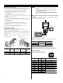
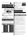
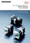
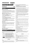
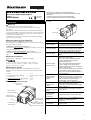
HM-60074-2
OPERATING MANUAL
All-in-One 5-Phase Stepping Motor
PKA Series
KCC-REMOMC-061
Thank you for purchasing an Oriental Motor product.
This Manual describes product handling procedures and safety
precautions.
• Please read it thoroughly to ensure safe operation.
• Always keep the manual where it is readily available.
Front side
Introduction
Before use
Only qualified personnel should work with the product.
Use the product correctly after thoroughly reading the section "Safety
precautions."
The product described in this manual has been designed and manufactured
for use in general industrial equipment. Do not use for any other purpose. For
the motor power supply, use a DC power supply with reinforced insulation
on its primary and secondary sides.
Oriental Motor Co., Ltd. is not responsible for any damage caused through
failure to observe this warning.
Operating Manuals for the PKA Series
Operating manuals for the PKA Series are listed below.
After reading the above manuals, keep them in a convenient place so that you
can reference them at any time.
Pilot
Output shaft
Name
PWR LED (Green)
ALM LED (Red)
• PKA Series USER MANUAL (CD-ROM)
This manual explains the function, installation and connection of the motor as
well as operating method.
DAT LED (Green)
• PKA Series OPERATING MANUAL (this document)
This manual explains safety precautions, connector pin assignments and
others.
ERR LED (Red)
Hazardous substances
RoHS (Directive 2002/95/EC 27Jan.2003) compliant
한국전파법
이 기기는 업무용 (A급) 전자파적합기기로서 판매자 또는
사용자는 이 점을 주의하시기 바라며, 가정외의 지역에서
사용하는 것을 목적으로 합니다.
Function setting
switches (SW1)
Checking the product
Verify that the items listed below are included. Report any missing or
damaged items to the branch or sales office from which you purchased the
product.
•
•
•
•
•
Motor................................................................1 unit
CN1 leadwire/connector assembly ..................1 pc. [0.6 m (2 ft.), 12-pins]
Connector cap ..................................................2 pcs.
OPERATING MANUAL (this document)......1 copy
USER MANUAL (CD-ROM) .........................1 pc.
Names and functions of parts
Transmission rate
setting switch
(SW3)
Mounting holes
(4 locations)
Power supply and
I/O signal connector
(CN1)
RS-485
communication
connectors
(CN2/CN3)
Transmission rate
setting switch (SW3)
Address number
setting switch (SW2)
LED
Function setting
switches (SW1)
Address number
setting switch
(SW2)
Power supply and
I/O signal connector
(CN1)
RS-485 communication
connectors (CN2, CN3)
Data edit connector
(CN4)
Mounting holes
(4 locations)
Description
This LED is lit while the power is input.
This LED will blink when an alarm generates.
It is possible to check the generated alarm by
counting the number of times the LED blinks.
This LED will blink or illuminate steadily when
the driver is communicating with the master
station properly via RS-485 communication.
This LED will illuminate when a RS-485
communication error occurs with the master
station.
Use this switch when controlling the system
via RS-485 communication.
• No.1, No.2: Set the termination resistor
(120 Ω) of RS-485 communication.
(Factory setting: OFF)
• No.3: Using this switch and the address
number setting switch (SW2), set the
address number of RS-485 communication.
(Factory setting: OFF)
• No.4: Set the connection device of RS-485
communication. (Factory setting: OFF)
• No.5, No.6: Not used. (Keep this switch in
the OFF position.)
Use this switch when controlling the system
via RS-485 communication. Use this switch
and SW1-No.3 of the function setting switch,
to set the address number of RS-485
communication. (Factory setting: 0)
Use this switch when controlling the system
via RS-485 communication. Set the
transmission rate of RS-485 communication
(Factory setting: 7).
Connect the main power supply (+24 VDC)
and I/O signals.
Connect the RS-485 communication cable.
Connect a PC in which the MEXE02 has been
installed, or the OPX-2A (both are
accessories).
Secure the motor with screws using these
mounting holes.
Data edit connector (CN4)
1
Installation
Connection
Note
Location for installation
The motor has been designed and manufactured to be installed within another
device. Install it in a well-ventilated location that provides easy access for
inspection. The location must also satisfy the following conditions:
• Inside an enclosure that is installed indoors (provide vent holes)
• Operating ambient temperature 0 to +50 °C (+32 to +122 °F)
[non-freezing]
• Operating ambient humidity 85% or less [non-condensing]
• Area that is free of explosive atmosphere or toxic gas (such as sulfuric gas)
•
•
•
•
•
•
•
•
or liquid
Area not exposed to direct sun
Area free of excessive amount of dust, iron particles or the like
Area not subject to splashing water (rain, water droplets), oil (oil droplets)
or other liquids
Area free of excessive salt
Area not subject to continuous vibration or excessive shocks
Area free of excessive electromagnetic noise (from welders, power
machinery, etc.)
Area free of radioactive materials, magnetic fields or vacuum
1000 m (3300 ft.) or lower above sea level
• Ensure that the connector plugged in securely. Insecure
connection may cause malfunction or damage to the
motor.
• When unplugging the connector, do so while pressing
the latches on the connector.
• When plugging/unplugging the connector, turn off the
power and wait for the PWR LED to turn off before doing
so.
Connection of power supply and I/O signals, grounding
motor
Connect the power supply and I/O signals to the motor using the supplied CN1
leadwire/connector assembly (12-pins).
DC power supply
24 VDC±10%
Installation method
+24 V
GND
The motor can be installed in any direction.
Install the motor onto an appropriate flat metal plate having excellent
vibration resistance and heat conductivity.
When installing the motor, secure it with four bolts (not supplied) through the
four mounting holes provided. Do not leave a gap between the motor and
metal plate.
Insert the pilot located on the motor's installation surface into the mounting
plate's.
• Installation method A
• Installation method B
Pilot
Metal plate
Pilot
Mounting hole
Nominal
size
PKA544KD
PKA566KD
M3
M4
Tightening
torque
[N·m (oz-in)]
1 (142)
2 (280)
Effective
depth of bolt
[mm (in.)]
4.5 (0.177)
−
FG
•
Connecting the power supply
Use a power supply that can supply the current capacity show in the table
below.
Model
Input power
supply voltage
PKA544KD
PKA566KD
24 VDC±10%
Power supply
current capacity
1.4 A or more
2.5 A or more
•
Mounting hole
Metal plate
Model
Programmable controller
Installation
method
A
B
Grounding method
Ground the Frame Ground terminal (FG) of pin No.1 as necessary.
Ground using a wire of AWG24 to 16 (0.2 to 1.25 mm2), and do not share the
Protective Earth Terminal with a welder or any other power equipment.
Pin assignments
•
CN1 connector pin assignments
Lead wire
color
Yellow
Black/White
Orange
Red/White
Green
Blue
Purple
Gray
White
Black
Brown
Red
Pin
No.
1
2
3
4
5
6
7
8
9
10
11
12
Signal
name
FG
GND
IN-COM
+24 VDC
IN0
IN1
IN2
IN3
OUT0+
OUT0−
OUT1+
OUT1−
12
2
11
1
Description∗
Frame Ground
Power supply GND
Input common
+24 VDC power supply input
Control input 0 (+LS)
Control input 1 (−LS)
Control input 2 (HOMES)
Control input 3 (STOP)
Control output 0 (ALM)
Control output 1 (READY)
∗ ( ): Initial value
2
•
4 3
CN2/CN3 connector pin assignments
2 1
Pin No.
1
2
3
4
Signal name
TR+
TR−
GND
FG
Description
RS-485 communication signal (+)
RS-485 communication signal (−)
GND
Frame Ground
•
Transmission rate
Set the transmission rate using transmission rate
setting switch (SW3). The transmission rate to be
set should be the same as the transmission rate of
the master device.
Factory setting 7 (625,000 bps)
Note
SW3
0
1
2
3
Transmission
rate (bps)
9600
19200
38400
57600
Do not set SW3 to positions 5 to F. The factory setting "7"
is the transmission rate for when connecting to the network
converter.
•
Termination resistor
Use a termination resistor for the motor located farthest away (positioned at
the end) from the programmable controller (master device).
Turn SW1-No.1 and No.2 of the function setting switch ON to set the
termination resistor for RS-485 communication (120 Ω).
Factory setting No.1 and No.2: Both OFF (termination resistor disabled)
Setting the switches
SW1- No.1, No.2
OFF
ON
Termination resistor (120 Ω)
Disabled
Enabled
Safety precautions
Function setting switches (SW1)
No.1, No.2: Set the termination resistor
No.3: Set the address number
No.4: Set the connection device
No.5, No.6: Not used
Note
Transmission rate
setting switch (SW3)
Address number
setting switch (SW2)
Be sure to turn off the motor power before setting the
switches. If the switches are set while the power is still on,
the new switch settings will not become effective until the
motor power is cycled.
•
Setting the connection device
Set the connection device of RS-485 communication using the function
setting switch SW1-No.4. Set to ON when controlling via Modbus protocol.
Factory setting OFF (Network converter)
SW1-No.4
ON
OFF
Connection device
General purpose master device (Modbus protocol)
Network converter
•
Address number (slave address)
Set the address number (slave address) using the address number setting
switch (SW2) and SW1-No.3 of the function setting switch. Make sure each
address number (slave address) you set for each driver is unique.
Address number (slave address) 0 is reserved for broadcasting, so do not use
this address.
Factory setting SW1-No.3: OFF, SW2: 0 (Address number 0)
SW1No.3
SW2
OFF
0
1
2
3
4
5
6
7
8
9
A
B
C
D
E
F
Address number
(slave address)
Not used
1
2
3
4
5
6
7
8
9
10
11
12
13
14
15
SW1No.3
SW2
ON
0
1
2
3
4
5
6
7
8
9
A
B
C
D
E
F
Address number
(slave address)
16
17
18
19
20
21
22
23
24
25
26
27
28
29
30
31
The precautions described below are intended to prevent danger or injury to
the user and other personnel through safe, correct use of the product. Use the
product only after carefully reading and fully understanding these
instructions.
Warning
Handling the product without observing the instructions that accompany a
"Warning" symbol may result in serious injury or death.
General
• Do not use the product in explosive or corrosive environments, in the
presence of flammable gases, locations subjected to splashing water, or
near combustibles. Failure to do so may result in fire or injury.
• Assign qualified personnel the task of installing, wiring,
operating/controlling, inspecting and troubleshooting the product. Failure
to do so may result in fire, injury or damage to equipment.
• When the power is shut off or the motor does not maintain excitation, the
motor will lose the holding torque. Take measures to keep the moving
parts in position for vertical operations such as elevator applications.
Failure to do so will cause the moving parts to fall and it may result in
injury or damage to equipment.
• Depending on the type of the alarm (protective function), the motor may
stop and lose its holding torque when the alarm generates. This may cause
injury or damage to equipment.
• When the motor generates an alarm (any of the motor's protective
functions is triggered), first remove the cause and then clear the protection
function. Continuing the operation without removing the cause of the
problem may cause malfunction of the motor, leading to injury or damage
to equipment.
Connection
• Keep the motor's input-power voltage within the specified range to avoid
fire.
• For the motor power supply, use a DC power supply with reinforced
insulation on its primary and secondary sides. Failure to do so may cause
electric shock.
• Connect the cables securely according to the wiring diagram in order to
prevent fire.
• Do not forcibly bend, pull or pinch the cable or lead wire. Doing so may
cause fire. Applying stress to the connection area of the connectors may
cause damage to the product.
Operation
• Turn off the power in the event of a power failure. Or the motor may
suddenly start when the power is restored and may cause injury or damage
to equipment.
• Do not turn the motor excitation OFF while operating. The motor will stop
its operation and lose the holding torque. This may cause injury or damage
to equipment.
• Configure an interlock circuit in sequence program so that the system
including the motor operates on the safe side when a RS-485
communication error generates.
3
Repair, disassembly and modification
• Do not disassemble or modify the motor. Refer all such internal
inspections and repairs to the branch or sales office from which you
purchased the product.
Caution
Handling the product without observing the instructions that accompany a
“Caution” symbol may result in injury or property damage.
General
• Do not use the motor beyond its specifications. Doing so may result in
injury or damage to equipment.
• Keep your fingers and objects out of the openings in the motor. Failure to
do so may result in fire or injury.
• Do not touch the motor during operation or immediately after stopping.
The surface is hot and may cause a skin burn(s).
Transportation
• Do not carry the motor by holding the motor output shaft or
leadwire/connector assembly. Doing so may cause injury.
Installation
• Install the motor in the enclosure in order to prevent injury.
• Keep the area around the motor free of combustible materials in order to
prevent fire or a skin burn(s).
• Provide a cover over the rotating parts (output shaft) of the motor. Failure
to do so may result in injury.
Connection
• The connectors CN1, CN2, CN3 and CN4 of the motor are not electrically
insulated. When grounding the positive terminal of the power supply, do
not connect any equipment (PC, etc.) whose negative terminal is grounded.
Doing so may cause the motor and these equipment to short, damaging
both.
• When connecting, check the indication of the motor and be sure to observe
the polarity of the power supply. Reverse-polarity connection may cause
damage to the motor. The power-supply circuit and the RS-485
communication circuit are not electrically insulated. Therefore, when
controlling multiple motors via RS-485 communication, the reverse
polarity of the power supply will cause a short circuit and may result in
damage to the motors.
Operation
• Provide an emergency stop device or emergency stop circuit external to
•
•
•
•
•
the equipment so that the entire equipment will operate safely in the event
of a system failure or malfunction. Failure to do so may result in injury.
Before supplying power to the motor, turn all input signals to the motor
OFF. Otherwise, the motor may start suddenly at power on and cause
injury or damage to equipment.
Set a suitable operation speed and acceleration/deceleration rate. Improper
setting may cause loss of the motor synchronism and moving the load to
an unexpected direction, which may result in injury or damage to
equipment.
Do not touch the rotating part (output shaft) during operation. Doing so
may cause injury.
When rotating the output shaft manually while the motor stops, cut off the
motor current by turning off the power supply or motor excitation. Failure
to do so may cause injury.
The motor surface temperature may exceed 70 °C (158 °F)
even under normal operating conditions. If the operator is
allowed to approach the running motor, attach a warning
label as shown below in a conspicuous position. Failure to
Warning
do so may result in skin burn(s).
label
• Immediately when trouble has occurred, stop running and turn off the
motor power. Failure to do so may result in fire or injury.
• Static electricity may cause the motor to malfunction or suffer damage.
While the motor is receiving power, do not touch the motor. Always use
an insulated screwdriver to adjust the motor's switches.
Disposal
• To dispose of the motor, disassemble it into parts and components as much
as possible and dispose of individual parts/components as industrial waste.
4
• Unauthorized reproduction or copying of all or part of this manual is
prohibited.
• Oriental Motor shall not be liable whatsoever for any problems relating
to industrial property rights arising from use of any information, circuit,
equipment or device provided or referenced in this manual.
• Characteristics, specifications and dimensions are subject to change
without notice.
• While we make every effort to offer accurate information in the
manual, we welcome your input. Should you find unclear descriptions,
errors or omissions, please contact the nearest office.
•
is a registered trademark or trademark of Oriental
Motor Co., Ltd., in Japan and other countries.
© Copyright ORIENTAL MOTOR CO., LTD. 2012
• Please contact your nearest Oriental Motor office for further information.
Technical Support Tel:(800)468-3982
8:30 A.M. to 5:00 P.M., P.S.T. (M-F)
7:30 A.M. to 5:00 P.M., C.S.T. (M-F)
E-mail: [email protected]
www.orientalmotor.com
Headquarters and Düsseldorf Office
Tel:0211-52067-00
Fax:0211-52067-099
Munich Office
Tel:089-3181225-00 Fax:089-3181225-25
Hamburg Office
Tel:040-76910443
Fax:040-76910445
Tel:01256-347090
Fax:01256-347099
Tel:01 47 86 97 50
Fax:01 47 82 45 16
Tel:02-93906346
Fax:02-93906348
Tel:400-820-6516
Fax:021-6278-0269
Tel:(02)8228-0707
Fax:(02)8228-0708
Tel:+65-6745-7344
Fax:+65-6745-9405
Tel:(03)22875778
Fax:(03)22875528
Tel:+66-2-251-1871
Fax:+66-2-251-1872
KOREA
Tel:080-777-2042
Fax:02-2026-5495
Headquarters Tokyo, Japan
Tel:03-6744-0361
Fax:03-5826-2576