1
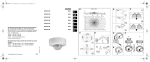
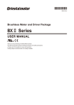
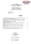
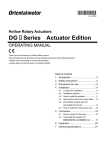
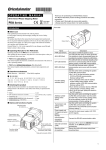
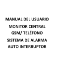
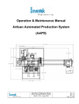
HM-5112
OPERATING MANUAL
Brushless DC Motor and Driver Package
BLV Series
• Assign qualified personnel the task of installing, wiring,
Introduction
Before using the motor
Only qualified personnel should work with the product.
Use the product correctly after thoroughly reading the "Safety precautions".
The product described in this manual has been designed and manufactured
for use in general industrial machinery, and must not be used for any other
purpose. Oriental Motor Co., Ltd. is not responsible for any damage caused
through failure to observe this warning.
Operating manuals for the BLV Series
Operating manuals for the BLV Series are listed below. Read the manuals
carefully before using your BLV Series unit.
• BLV Series OPERATING MANUAL (This document)
This manual explains the motor and driver functions as well as installation
method, and others.
• BLV Series USER MANUAL Basic function
This manual explains the motor and driver functions, how to install/connect
and troubleshooting, among others. Also, it explains operations using an
accessory data setter OPX-2A.
• BLV Series USER MANUAL RS-485 Communication Mode
This manual explains how to control the motor via RS-485 communication
using a programmable controller.
CE Marking
This product has been certified under the CE Marking requirements (EMC
Directive) based on the EN Standard. Because the input power supply
voltage of this product is 24 VDC/48 VDC, it is not subject to the Low
Voltage Directive. However, install and connect this product as follows.
• Installation conditions
Motor and driver are to be used as a component within other equipment.
Overvoltage category: I
Pollution degree: 2
• EMC Directive
Refer to USER MANUAL Basic Function for installation method.
Hazardous substances
RoHS (Directive 2002/95/EC 27Jan.2003) compliant
Safety precautions
The precautions described below are intended to prevent danger or injury to
the user and other personnel through safe, correct use of the product. Use the
product only after carefully reading and fully understanding these
instructions.
Handling the product without observing the
Warning instructions that accompany a "Warning" symbol
Caution
Note
Thank you for purchasing an Oriental Motor product.
This Operating Manual describes product handling procedures and
safety precautions.
• Please read it thoroughly to ensure safe operation.
• Always keep the manual where it is readily available.
may result in serious injury or death.
Handling the product without observing the
instructions that accompany a "Caution" symbol
may result in injury or property damage.
The items under this heading contain important
handling instructions that the user should observe to
ensure safe use of the product.
Warning
General
• Do not use the product in explosive or corrosive environments, in the
presence of flammable gases, locations subjected to splashing water, or
near combustibles. Failure to do so may result in fire, electric shock or
injury.
operating/controlling, inspecting and troubleshooting the product. Failure
to do so may result in fire, electric shock, injury or damage to equipment.
• Do no use any standard type in a vertical application. If the driver
protection function is activated, the motor will stop and the moving part of
the equipment will drop, thereby causing injury or equipment damage.
• Do not use the brake mechanism of the motor with electromagnetic brake
as a safety brake. It is intended to hold the movable parts and motor
position. This caution is to avoid personal injury or damage to the
equipment.
• When the driver's protection function is triggered, first remove the cause
and then clear the protection function. Continuing the operation without
removing the cause of the problem may cause malfunction of the motor
and driver, leading to injury or damage to equipment.
Installation
• Install the motor (gearhead) and driver in the enclosure in order to prevent
injury.
Connection
• Keep the driver's input-power voltage within the specified range to avoid
fire.
• For the power supply, use a DC power supply with reinforced insulation
on its primary and secondary sides. Failure to do so may cause electric
shock.
• Connect the cables securely according to the wiring diagram in order to
prevent fire.
• Do not forcibly bend, pull or pinch the cable. Doing so may cause fire.
• Do not machine or modify the motor cable or extension cable. Doing so
may result in fire.
• Be sure to observe the specified cable sizes. Use of unspecified cable sizes
may result in fire.
• Observe the specified screw tightening torque when connecting terminals
to the connector. Failure to do so may result in fire or equipment damage.
Operation
• Use a specified motor (gearhead) and driver combination. Failure to do so
may result in fire or equipment damage.
Maintenance/inspection
• Always turn off the power before performing maintenance/inspection.
Failure to do so may result in injury.
• Regularly check the openings in the driver for accumulated dust.
Accumulated dust may cause fire.
Repair, disassembly and modification
• Do not disassemble or modify the motor (gearhead) and driver. This may
cause electric shock or injury. Refer all such internal inspections and
repairs to the branch or sales office from which you purchased the
product.
Caution
General
• Do not use the motor (gearhead) and driver beyond its specifications, or
injury or damage to equipment may result.
• Keep your fingers and objects out of the openings in the driver, or fire or
injury may result.
• Do not touch the motor (gearhead) and driver during operation or
immediately after stopping. The surface is hot and may cause a skin
burn(s).
Installation
• To prevent the risk of damage to equipment, leave nothing around the
motor and driver that would obstruct ventilation.
• Do not hold the motor (gearhead) output shaft or cable. This may cause
injury.
1
• Do not touch the motor output shaft (key groove or pinion) with bare
•
•
•
•
•
hands. Doing so may result in injury.
When assembling the motor with the gearhead, exercise caution not to
pinch your fingers or other parts of your body between the motor and
gearhead. Injury may result.
Securely affix the motor (gearhead) and driver to their respective
mounting plates. Inappropriate installation may cause the motor/driver to
detach and fall, resulting in injury or equipment damage.
Provide a cover over the rotating parts (output shaft) of the motor
(gearhead) to prevent injury.
When installing the motor (gearhead) in the equipment, exercise caution
not to pinch your fingers or other parts of your body between the
equipment and motor or gearhead. Injury may result.
Securely install the load on the motor (gearhead) output shaft.
Inappropriate installation may result in injury.
Operation
• Do not shut off the negative side of the power supply during operation.
Also, note that the wiring for the power supply does not disconnect. Doing
so may cause damage to equipment.
• Provide an emergency stop device or emergency stop circuit external to
the equipment so that the entire equipment will operate safely in the event
of a system failure or malfunction. Failure to do so may result in injury.
• Immediately when trouble has occurred, stop running and turn off the
driver power. Failure to do so may result in fire, electrical shock or injury.
• Do not touch the rotating part (output shaft) during operation. This may
cause injury.
• The motor surface temperature may exceed 70 °C even
under normal operating conditions. If the operator is
allowed to approach the running motor, attach a warning
Warning
label as shown below in a conspicuous position. Failure to
label
do so may result in skin burn(s).
Disposal
• To dispose of the motor (gearhead) and driver, disassemble it into parts
and components as much as possible and dispose of individual
parts/components as industrial waste.
Precautions for use
• Regeneration energy
When using the motor in operation such as vertical drive (gravitational
operation) or sudden starting/stopping of a inertial load, regeneration energy
may generate. Since the driver has no function to consume regeneration
energy, if the output capacity or overvoltage allowance of the DC power
supply is small, the protective function for the power supply or driver may
activate and the motor may stop. When performing these operations, use a
DC power supply or battery that has a large output capacity or overvoltage
allowance.
Also, use an electromagnetic brake motor not to drop the moving part in
vertical drive (gravitational operation).
If protective function for the power supply or driver is activated, contact
your nearest Oriental Motor sales office.
• Do not use a solid-state relay (SSR) to turn on/off the power
A circuit that turns on/off the power via a solid-state relay (SSR) may
damage the motor and driver.
• Grease measures
On rare occasions, a small amount of grease may ooze out from the gearhead.
If there is concern over possible environmental damage resulting from the
leakage of grease, check for grease stains during regular inspections.
Alternatively, install an oil pan or other device to prevent leakage from
causing further damage. Oil leakage may lead to problems in the customer’s
equipment or products.
• Apply grease to the output shaft of a hollow shaft flat gearhead
If you are using a hollow shaft flat gearhead, apply grease (molybdenum
disulfide grease, etc.) on the surface of the load shaft and inner walls of the
hollow output shaft to prevent seizure.
• Preventing electrical noise
Refer to USER MANUAL Basic Function for measures with regard to noise.
• Conduct the insulation resistance measurement or withstand
voltage test separately on the motor and the driver.
Conducting the insulation resistance measurement or withstand voltage test
with the motor and driver connected may result in injury or damage to
equipment.
2
• Note on connecting a power supply whose positive terminal is
grounded
The driver's main power supply input terminal (CN1), I/O signal connector
(CN3), communication connector (CN5/CN6/CN7) and control power
supply input terminal (TB1) are not electrically insulated.
When grounding the positive terminal of the power supply, do not connect
any equipment (PC, etc.) whose negative terminal is grounded. Doing so
may cause the driver and these equipment to short, damaging both.
• The driver uses semiconductor elements. Handle the driver with
care.
The driver uses parts that are sensitive to electrostatic charge. Before
touching the driver, turn off the power to prevent electrostatic charge from
generating. If an electrostatic charge is impressed on the driver, the driver
may be damaged.
• Use an extension cable (supplied) when extending the wiring
distance between the motor and driver
Preparation
Checking the product
Verify that the items listed below are included. Report any missing or
damaged items to the branch or sales office from which you purchased the
product.
•
•
•
•
•
Motor (with a gearhead, only for combination type) ..........1 unit
Driver.....................................................................................1 unit
Extension cable......................................................................1 pc.
CN1 connector .....................................................................1 pc.
OPERATING MANUAL (this document) ...........................1 copy
Accessories for combination type
• Hexagonal socket head screw set ........................................................ 1 set
• Parallel key ........................................................................................ 1 pc.
(Secured to the gearhead output shaft on the parallel shaft gearhead)
• Safety cover ....................................................................................... 1 pc.
(Supplied with the hollow shaft flat gearhead)
• Safety cover mounting screw .............................................................. 2 pcs.
(Supplied with the hollow shaft flat gearhead)
Combinations of motors and drivers
Verify the model number of the purchased unit against the number shown on
the package label. Check the model number of the motor and driver against
the number shown on the nameplate.
• in the model names indicates a number representing the gear ratio.
• indicates a number representing the length of an extension cable.
• The combination types come with the motor and gearhead pre-assembled.
•
Standard type
• Combination type parallel shaft gearhead
Unit model
Motor model
BLV620K SBLV640N S-
BLVM620K-GFS
BLVM640N-GFS
Gearhead
model
GFS6G
Driver model
BLVD20KM
BLVD40NM
• Combination type hollow shaft flat gearhead
Gearhead
model
Unit model
Motor model
BLV620K FBLV640N F-
BLVM620K-GFS
BLVM640N-GFS
GFS6G FR
Motor model
BLVM620K-A
BLVM640N-A
Driver model
BLVD20KM
BLVD40NM
• Round shaft type
Unit model
BLV620KABLV640NA-
Driver model
BLVD20KM
BLVD40NM
•
Name
Electromagnetic brake type
• Combination type parallel shaft gearhead
Unit model
BLV620KM SBLV640NM S-
Motor model
BLVM620KM-GFS
BLVM640NM-GFS
Gearhead
model
GFS6G
I/O signal connector
[CN4]
Driver model
BLVD20KM
BLVD40NM
Basic function switches
[SW1]
Communication
connector [CN7]
Control power supply
input terminal∗ [TB1]
RS-485 communication
connector∗ [CN5/CN6]
• Combination type hollow shaft flat gearhead
Unit model
BLV620KM FBLV640NM F-
• Round shaft type
Unit model
BLV620KMABLV640NMA-
Motor model
Gearhead
model
BLVM620KM-GFS
BLVM640NM-GFS
GFS6G FR
Motor model
BLVM620KM-A
BLVM640NM-A
Driver model
BLVD20KM
BLVD40NM
Driver model
BLVD20KM
BLVD40NM
Names and functions of parts
•
Driver
Torque limiting
potentiometer [VR3]
Basic function switch
[SW1]
Mounting hole
(4 locations)
Communication function
switch [SW2]
Description
Use this connector when using an
external control device (programmable
controller) or inputting a operation
command.
Select type of speed response, external
DC voltage and sink logic/source logic.
Connect the OPX-2A.
Connect the driver control power supply.
Connect the RS-485 communication
cable.
This LED will illuminate when the driver is
C-DAT LED (Green) ∗
communicating with the master station
properly via RS-485 communication.
This LED will illuminate when a RS-485
C-ERR LED (Red) ∗
communication error occurs with the
master station.
Set the baud rate, communication
Communication function
protocol and termination resistor of
switch ∗ [SW2]
RS-485 communication.
Address number setting This switch set the address number (slave
switch∗ [SW3]
address) of RS-485 communication.
Mounting hole
4 locations on the back surface and side
(4 locations)
surface
∗ Use these switches when controlling the system via RS-485 communication.
• Motor
Illustration shows electromagnetic brake type.
I/O signal connector [CN4]
Electromagnetic brake
Mounting hole
(4 locations)
Address number setting
switch [SW3]
POWER LED (Green)
C-DAT LED (Green)
C-ERR LED (Red)
ALARM LED (Red)
Output shaft
Internal potentiometer [VR1]
RS-485 communication
connector [CN5/CN6]
Communication
connector [CN7]
Electromagnetic brake
connector [CN8]
Acceleration/deceleration
time potentiometer [VR2]
Motor signal connector
[CN3]
Motor
Motor power connector
[CN2]
Pilot section
Motor cable
Control power supply
input terminal [TB1]
Electromagnetic brake
connector
Motor signal cable
Main power supply input
terminal [CN1]
Motor power cable
Installation
Name
POWER LED (Green)
ALARM LED (Red)
Internal potentiometer
[VR1]
Acceleration/
deceleration time
potentiometer [VR2]
Torque limiting
potentiometer [VR3]
Main power supply input
terminal [CN1]
Motor power connector
[CN2]
Motor signal connector
[CN3]
Electromagnetic brake
connector [CN8]
Description
This LED lit while the main power or
control power is input.
This LED will blink when an alarm
generates (a protective function is
triggered). You can check the generated
alarm by counting the number of times
the LED blinks.
Location for installation
The motor and driver are designed and manufactured for installation in
equipment. Install them in a well-ventilated location that provides easy
access for inspection. The location must also satisfy the following
conditions:
• Inside an enclosure that is installed indoors (provide vent holes)
• Operating ambient temperature
Set the operating speed of the motor.
Set the acceleration time and
deceleration time for the motor.
Set the torque limiting value of the motor.
Connect the main power supply.
BLV620: +24 V, BLV640: +48 V
Connect the motor power connector.
Connect the motor signal connector.
Connect the electromagnetic brake
connector.
•
•
•
•
•
•
•
•
•
Motor: 0 to +40 °C [+32 to 104 °F] (non-freezing)
Driver: 0 to +40 °C [+32 to 104 °F] (non-freezing)
Operating ambient humidity 85% or less (non-condensing)
Area not exposed to direct sun
Area free of excessive amount of dust, iron particles or the like
Area free of excessive salt
Area that is free of explosive atmosphere or toxic gas (such as sulfuric
gas) or liquid
Area not subject to splashing water (rain, water droplets), oil (oil droplets)
or other liquids
Area not subject to continuous vibration or excessive shocks
Area free of excessive electromagnetic noise (from welders, power
machinery, etc.)
Area free of radioactive materials, magnetic fields or vacuum
3
Installing the combination type
Note
• Do not forcibly assemble the motor and gearhead. Also,
do not let metal objects or other foreign matter enter the
gearhead. The pinion or gear of the motor output shaft
may be damaged, resulting in noise or shorter service
life.
• Do not allow dust to attach to the pilot sections of the
motor and gearhead. Also, assemble the motor and
gearhead carefully by not pinching the O-ring at the
motor’s pilot section. If the O-ring is crushed or severed,
grease may leak from the gearhead.
Safety cover
mounting screw
Safety cover
Hexagonal socket
head screw
Rear
Front
•
Combination type parallel shaft gearhead
Install the hexagonal socket head
Hexagonal socket
screw in the four mounting holes
head screw
you drilled and tighten the nuts until
no gaps remain between the motor
and mounting plate.
Mounting plate
Removing/Installing the gearhead
To replace the gearhead or change the cable outlet direction, remove the
screws assembling the gearhead. The gearhead can be removed and the
motor cable position changed to one of three 90° directions.
Note that the motor cable cannot be positioned in the direction where the
cable faces the gearhead output shaft.
1. Remove the hexagonal socket head screws (4 pcs.) attaching the gearhead
and motor and detach the motor from the gearhead.
Tightening torque
Maximum applicable plate
Nominal size
[N·m (lb-in)]
thickness [mm (in.)].∗
M8
15.5 (137)
12 (0.47)
∗ When the supplied hexagonal socket head screw set is used.
2. Using the pilot sections of the motor and gearhead as guides, install the
motor to the gearhead and tighten the hexagonal socket head screws.
Install the motor carefully to prevent the pinion of the motor output shaft
from contacting the casing or gear of the gearhead.
Removing/Installing the gearhead
To replace the gearhead or change the cable outlet direction, remove the
screws assembling the gearhead. The gearhead can be removed and the
motor cable position changed to a desired 90° direction.
1. Remove the hexagonal socket head screws (2 pcs.) assembling the motor
and gearhead and detach the motor from the gearhead.
2. Using the pilot sections of the motor and gearhead as guides, install the
gearhead to the motor and tighten the hexagonal socket head screws.
When installing the gearhead, slowly rotate it
clockwise/counterclockwise to prevent the pinion of the motor output
shaft from contacting the side panel or gear of the gearhead.
Hexagonal socket
head screw
Change the cable
position to a desired
90° direction.
Hexagonal socket head screw
Change the cable
position to a desired
90° direction.
M3
Tightening torque
[N·m (lb-in)]
0.6 (5.3)
• Combination type hollow shaft flat gearhead
A combination type hollow shaft flat gearhead can be installed by using
either its front or rear side as the mounting surface. Install the supplied
hexagonal socket head screw set in the four mounting holes you drilled and
tighten the nuts until no gaps remain between the motor and mounting plate.
Since hexagonal nuts are not included with the product, provide them
separately or drill tapped holes in the mounting plate.
Also, attach the supplied safety cover to the hollow output shaft on the end
opposite from the one where the load shaft is installed.
Tightening torque
Maximum applicable plate
[N·m (lb-in)]
thickness [mm (in.)].∗
M8
15.5 (137)
12 (0.47)
∗ When the supplied hexagonal socket head screw set is used.
Nominal size
4
Nominal size
M8
Assembly screws
Nominal size
Assembly screws
Tightening torque
[N·m (lb-in)]
15.5 (137)
Installing the round shaft type
Install the hexagonal socket head screw in
the four mounting holes you drilled and
tighten the nuts until no gaps remain
between the motor and mounting plate.
Since hexagonal socket head screws are not
included with the product. They must be
provided by the customer.
Hexagonal socket
head screw
Nominal size
M8
Install the motor to a mounting plate of the following size or larger, so that
the motor case temperature will not exceed 90 °C (194 °F).
Unit model
BLV620
BLV640
Size of mounting
plate [mm (in.)]
200×200 (7.87×7.87)
250×250 (9.84×9.84)
Thickness
[mm (in.)]
5 (0.2)
6 (0.24)
Material
Aluminum
When installing a load on the motor (gearhead), align the center of the motor
output shaft (gearhead output shaft) with the center of the load shaft.
Note
•
• When coupling the motor (gearhead) with a load, pay
attention to centering, belt tension, parallelism of pulleys,
etc. Also, securely affix the tightening screws of the
coupling or pulleys.
• When installing a load, do not damage the motor output
shaft (gearhead output shaft) or bearing. Forcing in the
load by driving it with a hammer, etc., may break the
bearing. Do not apply any excessive force to the output
shaft.
• Do not modify or machine the motor (gearhead) output
shaft. The bearing may be damaged or motor (gearhead)
may break.
• Stepped load shaft
Install each hexagonal socket head screw over a retaining ring, spacer, flat
washer and spring washer and securely affix the ring.
Hexagonal socket
head screw
Spring washer
Flat washer
Spacer
Retaining ring
Parallel key
Retaining ring
Load shaft
Output shaft shape
Stepped
load shaft
Combination type parallel shaft gearhead
A key groove is provided on the output shaft of each combination type
parallel shaft gearhead. Form a key groove on the load side and affix the load
using the supplied parallel key.
Round shaft type
A flat section is provided on the motor output shaft of each round shaft type.
Apply a double-point screw, etc., at the flat section to securely affix the load
and prevent it from spinning.
• How to install a load
Using a coupling
Align the centerline of the motor (gearhead) output shaft with the centerline
of the load shaft.
When using the output axis tip screw
hole of a gearhead
Use a screw hole [M6; Effective depth
12 mm (0.47 in)] provided at the tip of
the output shaft as an auxiliary means
for preventing the transfer mechanism
from disengaging.
Hexagonal socket
head screw
Spring washer
Flat washer
Spacer
Retaining ring
Spacer
Parallel key
Retaining ring
Hollow output shaft
Transmission
parts
Spacer
• Non-stepped load shaft
Install each hexagonal socket head screw over a retaining ring, spacer, flat
washer and spring washer and securely affix the ring. Also insert a spacer on
the load shaft side.
Flat washer
Fixed screw
Load shaft
Hexagonal socket
head screw
Spacer
Load shaft
Screw
Spring washer
Parallel key
Note
Apply grease (molybdenum disulfide grease, etc.) on the
surface of the load shaft and inner walls of the hollow
output shaft to prevent seizure.
Recommended load shaft installation dimensions
[Unit: mm (in.)]
Inner diameter of
hollow shaft (H8)
Ø25+0.033
0
)
(0.9843+0.0013
0
Recommended diameter
of load shaft (h7)
0
Ø25-0.021
0
)
(0.9843-0.0008
Applicable screw
Spacer thickness
M10
6 (0.24)
Nominal diameter of
retaining ring
Ø25 (0.98)
Outer diameter of stepped
shaft (ØD)
40 (1.57)
Spacer
Spacer
Permissible overhung load and permissible thrust load
If the motor is subject to a strong impact upon instantaneous stop or receives
a large overhung load, use a stepped load shaft.
•
Spring washer
Hollow output shaft
Installing a load of the combination type hollow shaft
flat gearhead
Note
Hexagonal socket
head screw
Parallel key
Using a belt
Adjust the motor (gearhead) output shaft to lie parallel with the load shaft
and form right angles between the output shaft/load shaft and the line
connecting the centers of both pulleys.
Using a gear
Adjust the motor (gearhead) output shaft to lie parallel with the gear shaft
and allow the output shaft to mesh correctly with the centers of the gear
teeth.
Flat washer
ØD
Installing a load of the combination type parallel
gearhead or round shaft type
•
If the overhung load or thrust load exceeds the specified
allowable value, repeated load applications may cause the
bearing or output shaft of the motor (gearhead) to undergo
a fatigue failure.
Combination type parallel shaft gearhead
Distance from tip of gearhead output
Permissible
shaft and permissible overhung load∗
thrust load
[N (lb.)]
[N (lb.)]
10 mm (0.39 in.)
20 mm (0.79 in.)
550 (123)
800 (180)
200 (45)
5 to 20
<500 (112)>
<700 (157)>
1000 (220)
1250 (280)
300 (67)
30, 50
<900 (200)>
<1100 (240)>
1400 (310)
1700 (380)
400 (90)
100, 200
<1200 (270)>
<1400 (310)>
∗ The values assume a rated speed of 3000 r/min or below.
The values in < > are based on a rated speed of 4000 r/min.
Gear
ratio
5
Distance from gearhead mounting
Permissible
surface and permissible overhung
thrust load
Gear ratio
∗
load [N (lb.)]
[N (lb.)]
10 mm (0.39 in.) 20 mm (0.79 in.)
1230 (270)
1070 (240)
5 (BLV640 only)
<1130 (250)>
<990 (220)>
10
1680 (370)
1470 (330)
800 (180)
15, 20
<1550 (340)>
<1360 (300)>
2040 (450)
1780 (400)
30 to 100
<1900 (420)>
<1660 (370)>
∗ The values assume a rated speed of 3000 r/min or below.
The values in < > are based on a rated speed of 4000 r/min.
•
• Installing with screws
Affix the driver through the mounting holes using two screws (M4: not
supplied).
When mounting in vertical direction [Unit: mm (in.)]
A
B
• When using
side surface A
Round shaft type
Distance from tip of motor output shaft
and permissible overhung load [N (lb.)]
10 mm (0.39 in.)
20 mm (0.79 in.)
221 (49)
When mounting in horizontal direction [Unit: mm (in.)]
• When using side surface A
147 (5.79)
Installing the driver
A
The driver is designed so that heat is dissipated via air convection and
conduction through the enclosure. Install the driver on a flat metal plate
having excellent vibration resistance and heat conductivity.
When two or more drivers are to be installed side by side, provide 20 mm
(0.79 in.) and 25 mm (0.98 in.) clearances in the horizontal and vertical
directions, respectively.
Note
• Install the driver in an enclosure whose pollution degree
is 2 or better environment, or whose degree of protection
is IP54 minimum.
• Do not cover the radiation vent of the driver.
• Do not install any equipment that generates a large
amount of heat or noise near the driver.
• If the ambient temperature of the driver exceeds 40 °C
(104 °F), revise the ventilation condition or force-cool the
area around the driver using a fan.
Ø4.5 (0.177)
• When using side surface B
147 (5.79)
B
2×Ø4.5 (0.177)
Setting
Basic function switch [SW1]
• Mounting to DIN rail
When mounting the driver to a DIN rail, use a separately sold DIN rail
mounting plate (model number: PADP03) and attach it to a 35 mm (1.38 in.)
wide DIN rail. After installation, fix the both sides of the driver with the end
plate (not supplied).
DIN rail
mounting plate
2×Ø4.5
(0.177)
Permissible thrust load
[N (lb.)]
Not to exceed one-half
the motor’s mass ∗
∗ Minimize the thrust load. If a thrust load must be applied, do not let it
exceed one-half the motor’s mass.
197 (44)
Ø4.5
(0.177)
• When using
side surface B
147 (5.79)
Combination type hollow shaft flat gearhead
147 (5.79)
•
Communication function
switch [SW2]
Address number setting
switch [SW3]
Hook
Basic function (SW1)
SW1
1
DIN rail
Mounting hole
(M3-4 locations)
DIN lever
Mounting screw (supplied)
Tightening torque: 0.3 to 0.4 N·m (2.6 to 3.5 lb-in)
Note
• Do not use the mounting holes (M3, four locations) for
the DIN rail mounting plate for any purpose other than
securing the DIN rail mounting plate.
• Be sure to use the supplied screws when securing the
DIN rail mounting plate. The use of screws that would
penetrate 3 mm (0.12 in.) or more through the surface of
the driver may cause damage to the driver.
Description
Speed response
2
External DC voltage
3
Sink logic/Source
logic
Setting range
ON: High-response
OFF: Low-response (Factory setting)
ON: 0 to 10 V
OFF: 0 to 5 V (Factory setting)
ON: Source logic
OFF: Sink logic (Factory setting)
Communication function (SW2)
SW2
1
2
3
4
5
6
7
8
Description
Factory setting
Baud rate
Not used
communication protocol
Not used
termination resistor
Extending the address number
OFF
Address number setting (SW3)
Set the address number using the SW3 and No. 8 of the communication
function switch (SW2).
Factory setting : 0
6
Connection
Connection example (Sink logic)
Driver
CN1
DC power supply
BLV620: 24 VDC±10%
BLV640: 48 VDC±10%
+
+
-
-
+15 V
CN4
FWD
REV
STOP-MODE
M0
ALARM-RESET
MB-FREE
IN-COM
External DC voltage
(Not to exceed the
voltage selected by
SW1-No.2)
VM
3.3 kΩ
1
VL
VH
2
VM
1
VL
Motor power connector
CN3
Motor signal connector
CN8
Electromagnetic brake connector
2
3
4
9
CN4
10
6
5
External potentiometer
PAVR-20KZ
3
CN2
5
0V
0V
14
13
7
12
15
11
8
0V
SPEED-OUT
∗1
IN-COM
WNG (+)
∗2
WNG (-)
ALARM-OUT (+)
∗2
ALARM-OUT (-)
BLV620: 30 VDC or less
10 mA or less
BLV640: 53 VDC or less
10 mA or less
BLV620: 30 VDC or less
100 mA or less
BLV640: 53 VDC or less
100 mA or less
∗1 Connect a current-limiting resistor based on the power supply voltage if the current exceeds 10 mA.
∗2 Connect a current-limiting resistor based on the power supply voltage if the current exceeds 100 mA.
•
Connecting the power supply
•
Unit model
BLV620
BLV640
Connecting method
1. Strip the insulation cover of the lead wire by 10 mm (0.39 in.)
Applicable lead wire: AWG16 to 10 (1.25 to 6 mm2)
2. Insert each lead wire into the CN1 connector and tighten the screw.
Tightening torque: 0.7 to 0.8 N·m (6.1 to 7.0 lb-in)
3. Insert the CN1 connector into CN1.
10 mm
(0.39 in.)
CN1
connector
CN1
Input power supply voltage
24 VDC±10%
48 VDC±10%
Current capacity
800 W or more
1 kW or more
Connecting the motor and driver
Connect the motor cable to the motor power connector (CN2) and motor
signal connector (CN3) of the driver. When using a electromagnetic brake
motor, also connect to the electromagnetic brake connector (CN8).
To expand connection between the motor and driver, use the supplied
extension cable. Connection can be extended to a maximum of 3.5 m
(11.5 ft.).
Note
Have the connector plugged in securely. Insecure
connection may cause malfunction or damage to the motor
or driver.
Connecting the I/O signals
Lead wire
Note
Recommended power supply capacity
• When connecting, check the indication of the driver case
and pay attention to the polarity of the power supply.
Reverse-polarity connection may cause damage to the
driver.
• Do not wire the power supply cable of the driver in the
same cable duct with other power line or motor cable.
Doing so may cause malfunction due to noise.
• When cycling the power or plugging/unplugging the
connector, turn off the power and wait for the POWER
LED to turn off.
• When unplugging the CN1 connector, do so after
pressing the lever (orange) on the CN1.
Connecting the I/O signals to the I/O connector (CN4). Keep the wiring
distance as short as possible [less than 2 m (6.6 ft.)] to suppress the effect of
noise.
Note
• The connector for connecting the I/O signals are not
included. Please prepare as follows;
· D-Sub connector (15-pin)
· Hood (the screw: No.4-40UNC)
• Wire the signal cable at a distance of 100 mm (3.94 in.)
or more from the inductive load (electromagnetic relay
etc.), power supply or power cable (motor cable etc.).
• Applicable crimp terminal
If crimp terminals are used, select the following terminals.
Manufacturer
PHOENIX CONTACT
GmbH & Co. KG
Model
AI 1.5-10
AI 2.5-10
AI 4-10
AI 6-10
Applicable lead wire
2
AWG16 (1.25 mm )
2
AWG14 (2 mm )
2
AWG12 (3.5 mm )
2
AWG10 (6 mm )
7
•
Operation using a data setter OPX-2A
I/O connector function table
8 7
2 1
This figure is the CN4 connector
viewed from the driver front side.
15 14
Pin
No.
10 9
Signal
type
Terminal
name
Signal
name
1
X0
FWD
2
X1
REV
3
Input
4
5
GND
6
7
Output
X2
STOPMODE
X3
M0
C0
IN-COM
Y2
SPEEDOUT
Y1-
8
Y0-
9
X4
Input
10
11
12
13
X5
Analog
input
14
VL
VM
VH
Y1+
Output
15
Y0+
WNG (−)
ALARMOUT (−)
ALARMRESET
Description
The motor turns in the
clockwise direction.
The motor turns in the
counterclockwise
direction.
Select instantaneous stop
or deceleration stop.
Select the internal
potentiometer or external
potentiometer (external
DC voltage).
−
30 pulses are output with
each revolution of the
motor output shaft.
−
The following functions are extended when the OPX-2A is used. Refer to
OPX-2A OPERATING MANUAL for details.
• Operating speed with digital setting (maximum of 8 speeds)
• Acceleration time, Deceleration time (Individual setting)
• Torque limiting value with digital setting
• Change of I/O signal assignments
• Various displays (speed, alarm code, warning code, load factor)
• I/O monitor
• Warning output
• Test operation
• Data copy
Control via RS-485 communication
Modbus protocol can be used in RS-485 communication.
Refer to the USER MANUAL RS-485 Communication Mode for details.
−
Alarms are reset.
Select how the
electromagnetic brake
would operate when the
motor stops.
External speed setting
VL
input; Set the speed of the
VM
external potentiometer
VH
(external DC voltage).
This signal is output when
WNG (+)
a warning generates.
This signal is output when
ALARMan alarm generates
OUT (+)
(normally closed).
∗ Electromagnetic brake type only.
MB-FREE∗
Overview of the operation
Basic operation
With the BLV Series, you can perform following operations. Refer to USER
MANUAL Basic Function for details.
• Speed setting
Internal potentiometer, external potentiometer, external DC voltage
• Running/stopping the motor
Run/stop the motor by inputting operation control signals.
• Setting the acceleration time and deceleration time
You can set the acceleration time and deceleration time for starting and
stopping.
• 2-speed operation
Operation can be performed at two speeds through use of both the internal
potentiometer and external potentiometer (external DC voltage).
• Multi-motor control
A single external potentiometer (external DC voltage) can be used to set the
same speed for multiple motors.
• Unauthorized reproduction or copying of all or part of this manual is
prohibited.
• Oriental Motor shall not be liable whatsoever for any problems relating
to industrial property rights arising from use of any information, circuit,
equipment or device provided or referenced in this manual.
• Characteristics, specifications and dimensions are subject to change
without notice.
• While we make every effort to offer accurate information in the
manual, we welcome your input. Should you find unclear descriptions,
errors or omissions, please contact the nearest office.
•
is a registered trademark or trademark of Oriental
Motor Co., Ltd., in Japan and other countries.
© Copyright ORIENTAL MOTOR CO., LTD. 2011
• Please contact your nearest Oriental Motor office for further information.
Technical Support Tel:(800)468-3982
8:30 A.M. to 5:00 P.M., P.S.T. (M-F)
7:30 A.M. to 5:00 P.M., C.S.T. (M-F)
E-mail: [email protected]
www.orientalmotor.com
Headquarters and Düsseldorf Office
Munich Office
Hamburg Office
Tel:0211-52067-00
Tel:089-3181225-00
Tel:040-76910443
Fax:0211-52067-099
Fax:089-3181225-25
Fax:040-76910445
Tel:01256-347090
Fax:01256-347099
Tel:01 47 86 97 50
Fax:01 47 82 45 16
Tel:02-93906346
Fax:02-93906348
Tel:400-820-6516
Fax:021-6278-0269
Tel:+65-6745-7344
Fax:+65-6745-9405
Tel:(02)8228-0707
Fax:(02)8228-0708
Tel:(03)22875778
Fax:(03)22875528
Tel:+66-2-251-1871
Fax:+66-2-251-1872
KOREA
Tel:080-777-2042
Fax:02-2026-5495
Headquarters Tokyo, Japan
Tel:03-6744-0361
Fax:03-5826-2576
Printed on Recycled Paper
8