1
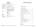
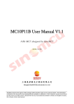
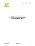
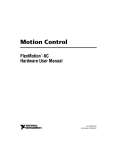
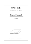
APPLICATION NOTE
1
ANALOG-TO-DIGITAL CONVERSION
TECHNIQUES USING ZILOG Z8® MCUS
A SEPARATE ADC CHIP ISN’T ALWAYS NECESSARY. MANY APPLICATIONS
REQUIRING A/D CONVERSIONS CAN BE ACHIEVED WITH 8-BIT MCUS—
AND WITHOUT COMPROMISING ACCURACY, SPEED, OR SYSTEM COST.
INTRODUCTION
Many embedded controller applications require an analog
voltage to be captured. Depending on the application, a
separate A/D converter (ADC) chip may be necessary because of the speed and resolution requirements. However,
many designs do not need fast conversion speeds, and 8
bits of resolution is adequate. For instance, a digital thermostat samples the temperature periodically and turns the
heater or air conditioner on or off when the temperature
hits a trip point. Here, the measurement speed for the voltage across a thermistor is not critical since the temperature
is changing rather slowly. In this case, conversion times on
the order of milliseconds are acceptable.
Capturing fast-changing signals, such as audio, requires a
much faster conversion rate. If the highest audio frequency
is 4 kHz coming into the ADC, the sample rate should be
at least twice this (8 kHz). Because of the limited processing time in between samples (in this case 125 µs), the ADC
must do a conversion quickly, so the MCU has time to process the data before the next sample.
Since most designs are cost-sensitive—especially in consumer electronics—there may not be the luxury of adding
relatively expensive ADC chips to the design. Design engineers must look for a more integrated solution, and Zilog
has the solution.
ZILOG Z8 MCU FEATURES
Zilog Z8® microcontrollers (MCUs) to which the following
A/D conversion techniques apply range in package sizes
from 18 to 44 pins. ROM sizes vary from 0.5 to 4 KB. These
are available in masked and OTP configurations, and can
be clocked up to 12 MHz using a RC, LC, ceramic resonator, or crystal oscillator (refer to Table 1).
■
Two power-down modes are available: HALT and STOP.
The block diagram of a typical Z8 architecture is shown in
Figure 1. Selected Zilog MCUs are shown in Table 1.
■
STOP completely shuts down the chip, including the
oscillator. To come out of STOP mode, you apply a
positive- or negative-going edge to one of the external
digital inputs or via the internal Watch-Dog Timer (WDT).
This application is set up via the Stop-Mode Recovery
(SMR) register.
HALT freezes code execution, but leaves the timers
enabled. The processor can exit HALT via an external or
internal interrupt.
AP97Z8X0901
1
Application Note
Analog-to-Digital Conversion Techniques Using Zilog Z8® MCUs
Zilog
Figure 1. Typical Z8 MCU Block Diagram
2
AP97Z8X0901
Application Note
Analog-to-Digital Conversion Techniques Using Zilog Z8® MCUs
Zilog
Table 1. Selected List of Zilog Z8 MCUs
Product Pin
Family Count
ROM
(KB)
RAM
(Bytes) I/O
Speed
(MHz)
1
Package Type
Z86C03
18
0.5
64
14
8
DIP, SOIC
Z86E03
18
0.5
64
14
8
DIP, SOIC
Z86C04
18
1
128
14
8
DIP, SOIC
Z86E04
18
1
128
14
8
DIP, SOIC
Z86C06
18
1
128
14
4, 12
DIP, SOIC
Z86E06
18
1
128
14
4, 12
DIP, SOIC
Z86C07
18
2
128
14
8, 12
DIP, SOIC
Z86E07
18
2
128
14
8, 12
DIP, SOIC
Z86C08
18
2
128
14
4, 12
DIP, SOIC
Z86E08
18
2
128
14
4, 12
DIP, SOIC
Z86C09
18
2
125
14
12
DIP, SOIC
Z86C16
18
1
128
14
8
DIP, SOIC
Z86C19
18
4
125
14
12
DIP, SOIC
Z86C30
28
4
256
24
12
DIP, SOIC
Z86E30
28
4
256
24
12
DIP, WIN
Z86C31
28
2
128
24
8
DIP
DIP
Z86E31
28
2
128
24
8
Z86C32
28
2
237
24
4, 8
DIP, SOIC
Z86C40
40/44
4
256
32
4, 12
DIP, PLCC, QFP
Z86E40
40/44
4
256
32
12
DIP, PLCC, QFP
Note: Masked ROM versions are indicated with the letter “C” (Z86C03, for
example); OTP versions are indicated with the letter “E” (Z86E03, for
example).
AP97Z8X0901
3
Application Note
Analog-to-Digital Conversion Techniques Using Zilog Z8® MCUs
4
Zilog
AP97Z8X0901
Application Note
Analog-to-Digital Conversion Techniques Using Zilog Z8® MCUs
Zilog
The on-board dual analog comparators, along with one
counter/timer, will be used to implement the ADC routines.
The analog comparators are multiplexed with the digital inputs on port pins P31, P32, and P33. This is depicted in
Figure 2.
The analog comparators are selected via the P3M register.
The comparators share a common reference pin, P33. The
input range of the comparators is 0-4V. The input offset
voltage is typically 10 mV with Vcc at 5.0V. The output of
the comparators may be examined by a TM instruction
(Test under Mask) on port P3. The outputs also generate
an interrupt, based on the falling or rising edge of the comparator output. These outputs also can connect to the P34
and P37 output pins under software control. The PCON
register in the extended register file controls this connection (not available on C04/E04 and C08/E08).
The comparators are enabled during HALT mode, but are
disabled in STOP mode. Three ADC configurations will be
presented:
■
PWM Ramp ADC
■
Successive Approximation ADC
■
RC Ramp ADC
R247 = P3M
D1
1 = Analog
0 = Digital
DIG.
P31 (AN1)
+
-
P32 (AN2)
P33 (REF)
+
-
IRQ. 2,TIN, P31 Data Latch
AN.
IRQ. 0,P32 Data Latch
IRQ. 1,P33 Data Latch
From Stop-Mode
Recovery Source
Figure 2. Port 3 Configuration
The software routines were designed around the
Z86C04/E04, but can be adapted for other selected Z8
MCUs.
AP97Z8X0901
The Zilog CCP emulator (Zilog PN Z86CCP00ZEM) was
used to test the routines . These routines are designed to
be “generic” in nature, meaning that they can be used with
other Z8 MCUs.
5
1
Application Note
Analog-to-Digital Conversion Techniques Using Zilog Z8® MCUs
Zilog
PWM RAMP ADC
Figure 3 depicts a Pulse-Width Modulated (PWM) ramp
and timer to implement a single-slope ADC. This method
has the advantage of being interrupt-driven, so that the
processor can perform other tasks while doing a conversion. The conversion time, however, is usually in the tens
of milliseconds. Here, a fixed-frequency square wave of
variable duty cycle begins at a low value and is steadily increased by incrementing the timer count at the end of each
sample period.
Generate the ramp by incrementing Timer 1’s value after
each sample period. Incrementing the count from 1 (01H)
to 200 (C8H) resets the ramp. The value loaded into the
register called DELAY determines the sample period. The
conversion speed is determined by the speed of the system clock, the analog-input voltage range, sample frequency, and the resolution of the timer.
In this example, the crystal frequency is 8 MHz, the input
voltage range is 0–4V, the sampling frequency is about
4800 kHz, and the resolution is 8-bits. This will yield a maximum conversion time of 40 ms.
The PWM output, (P00), is fed to a RC integrator, which
produces a linear ramp at the VREF input of the comparators at P33. Two analog voltages can be measured concurrently using this technique.The analog voltages to be
measured are sensed at P31 and P32. The voltage range
at these inputs is 0–4V.
If you know that the input voltage range is from 2–4V, then
you can restrict the ramp voltage to this range, which
yields a faster conversion time. Also, if 8-bits of resolution
is overkill, then adding two counts to the timer at the end
of each sample period will result in 7 bits of resolution.
Adding four counts yields 6 bits.
Refer to Code Listing 1 at the conclusion of this application
note, which shows the single-slope software routine.
Each comparator has its own interrupt level. When the
positive-going ramp exceeds the input voltage, the corresponding interrupt will then load the contents of the timer,
which is scaled to the measured analog input.
100K
11
P00
.1µF
Z86C03
Analog
IN
8
P31
Analog
IN
9
10
P32
P33
5
+5
+
-
+
-
GND
Vcc
14
+
10 µF
XTAL1
7
XTAL2
6
8 MHz
27pF
27pF
Figure 3. Single Slope ADC Using PWM Ramp
6
AP97Z8X0901
Application Note
Analog-to-Digital Conversion Techniques Using Zilog Z8® MCUs
Zilog
SUCCESSIVE APPROXIMATION ADC
For applications requiring faster conversion times, you
want to consider the successive approximation method
(see Figure 4). This routine, however, cannot be used in
background mode, which means that when a conversion is
taking place, the processor must drop what it’s doing and
call or jump to this routine. However, at the end of a conversion, it can then continue where it left off.
This method uses a Digital-to-Analog Converter (DAC) in
its feedback loop. The DAC is comprised of an R2R ladder
connected to port P2. When a binary value is output at Port
2, a DC voltage proportional to the binary value appears at
pin 1 of the ladder network. The DAC does a binary search
on the input voltage. This is achieved by first setting the
most significant bit (MSB) of the DAC and testing the comparator output. If the comparator output is zero, then the
DAC output for this bit is set to zero. If the comparator output is one, then the DAC output for this bit is set to one.
The bits from the output port 2 are individually tested in descending order, performing the same test. When all the
bits have been tested, the conversion is complete. The
output from the R2R resistor network becomes the comparator's reference voltage. The analog voltage to be measured can be connected to either P31 or P32, the non-inverting inputs of the comparators. The software for this
routine is shown in Code Listing 2.
To start the conversion, the MSB of P2 is set, resulting in
a voltage of half of VCC at the VREF input of the comparator.
If VCC is 5V, then this will be 2.5V. The non-inverting comparator input is then tested. If High, then the analog voltage must be 2.5V–5.0V.
The next bit, P26, is then set, and the input port is tested
again. If Low, then this bit is reset. The process continues
until all bits of P2 have been tested. The resultant value at
P2 is the digital representation of the analog input.
With a crystal frequency of 12 MHz, the conversion time is
approximately 70 µs. Even more resolution is available
from 10- and 12-bit R2R networks. Of course, more port
pins are then needed.
If a track-and-hold function is desired, analog switch
CD4016 can be added to the front end. In between samples, the switch is closed, charging a small capacitor.
At the end of each sample period—as determined by timer
T1—the switch is opened. Any error induced by trying to
convert a fast-changing analog input is eliminated. The
value of C is chosen so that the voltage across it tracks the
input voltage, does not bleed off during the conversion,
and follows the input voltage in between samples. For a
sampling rate of 8 kHz, the input frequency must be less
than or equal to 4 kHz to prevent distortion due aliasing.
Bourns
4610X-R2R-103
Optional Track-and-Hold
P27
26
P00
P26
13
Z86C40
ANALOG
IN
1
16 P31
2
33pF
17
18 P32
P33
CD4016
P25
+
+
-
11
+
10 µF
31
GND
XTAL1
27pF
3
2
4
6
37
7
36
8
35
9
P20
XTAL2
1
20K
38
P21
15
12 MHz
3
5
P23
Vcc
2
P24 39
P22
+5V
4
14
10K
10
27pF
Figure 4. Successive Approximation ADC
AP97Z8X0901
7
1
Application Note
Analog-to-Digital Conversion Techniques Using Zilog Z8® MCUs
Zilog
RC RAMP ADC
a counter tick period of 1 ms when the prescaler is set to
divide-by-1. When the capacitor voltage at P31 crosses
the unknown analog voltage at P33, the comparator will
switch, causing the counter/timer T1 to stop.
For cost-sensitive applications, consider the low-cost technique that is shown in Figure 5. Since this method uses a
logarithmic RC ramp for the comparator reference voltage,
the A/D result will not be a linear function of the input analog voltage. For many applications, such as some battery
chargers and peak detection circuits, linearity is not essential. If necessary, software compensation by look-up table
can be used to linearize the A/D result.
Code Listing 3 (at conclusion of this application note)
shows the routine, which gives a resolution of 8 bits and a
maximum conversion time of 256 µs for an oscillator frequency of 8 MHz. The accuracy is ± LSB. If the oscillator
frequency is changed, the RC values will need adjustment.
The analog input voltage range is 0–4V.
This method uses an externally generated RC ramp and a
counter/timer to measure the analog voltage at comparator input P33. The RC ramp is limited to the 4V common
mode range of the Z8 comparator. The C1 capacitor is
readied for conversion by briefly setting output P00. The
C1–P31 node will discharge to 4V, as determined by the
R1–R2 voltage divider. When conversion is started, P00 is
taken Low so that the C1–P31 node charges toward
ground through the parallel combination of R1 and R2.
Some applications require accurate detection of a single
threshold level. RC value tolerances can be adjusted out
with the addition of a single calibration. Simply replace R2
with a potentiometer and series resistor. Calibration is performed by putting the desired threshold voltage at P33
while adjusting the pot for desired result. Use a temperature stable capacitor, such as a ceramic NPO type, if wide
temperature variations are expected.
At the same time the ramp is initiated, counter/timer T1 is
started in gate mode. A crystal frequency of 8 MHz will give
+5V
Vcc
C1
10µF
Analog
Voltage
IN
+
C2
10µF
Z86C04
10 P33
8 P31
R1
100K
+
R2
22K
P00
XTAL1
7
XTAL2
8 MHz 6
27pF
27pF
Figure 5. A/D Converter Using RC Ramp
8
AP97Z8X0901
Zilog
Application Note
Analog-to-Digital Conversion Techniques Using Zilog Z8® MCUs
CONCLUSION
REFERENCE
You can see from the previous examples that applications
requiring analog-to-digital conversions can be achieved
without compromising accuracy, speed, or system cost.
Design engineers can experiment with the routines for optimum performance. These routines are designed to be
functions called from the main program; however, it is possible to modify the program so that it is completely interrupt-driven. This change allows the MCU to handle other
tasks in between the timer and comparator interrupts. By
adding a software UART routine to the above programs,
you can implement a truly low-cost, PC-compatible data
acquisition system.
1. Ciarcia, S., “Analog Interfacing In The Real World,”
Ciarcia’s Circuit Cellar, Vol. IV, 1984.
AP97Z8X0901
1
1. Distaso, L.A., “Analog to Digital Conversion Techniques With COPS Family Microcontrollers”, National
Semiconductor Corp., National Semiconductor Microcontroller Databook, 1987.
2. Zilog, Zilog Discrete Z8 Microcontroller Product
Specification Databook, DC 8318-02, Q3 1994.
3. Zilog, Zilog Z8 Microcontrollers User's Manual,
UM95Z8000103, 1995.
9
Application Note
Analog-to-Digital Conversion Techniques Using Zilog Z8® MCUs
Zilog
CODE LISTING 1
;***********************************************************************************************
;
SINGLE-SLOPE SOFTWARE ROUTINE
;
;
The PWM-generated ramp ADC uses two timers and counters and an RC integrator to find the
;
unknown input voltage. When the ramp voltage exceeds VIN, an interrupt is generated. The
;
value in timer T1 is the digital representation of this voltage.
;************************************************************************************************
delay_hi
.equ
r4
delay_lo
.equ
r5
delay
.equ
rr4
count
.equ
r6
irq_0
.equ
1
.org
0
.word
.word
.word
.word
.word
.word
comp_trip
0
0
0
timer_0
timer_1
.org
0ch
di
; disable interrupts
srp
#0
; set reg pointer 0-15h
ld
spl,#80h
; set stack pointer at top of stack
ld
p01m,#4
; internal stack
ld
p3m,#3
; active pull-ups on p2, comp on
ld
p2m,#0ffh
; inputs on p2
ld
pre0,#04h
; divide by one, one-shot
clr
t0
; t0 sets the sample period
ld
pre1,#06h
; divide by one, one-shot mode
ld
count,#4
; start counter with minimum count
ld
t1,count
; load counter
ld
p0,#04h
; take port pin P02 high to start
ld
imr,#31h
; load interrupt mask register
clr
irq
; clear interrupt request reg
clr
ipr
; clear interrupt priority reg
ld
tmr,#0fh
; load and enable both counters
wait_here:
ei
; enable interrupts
jr
wait_here
; wait for interrupts
;------------------------------------------------------------------------------------------------;
Timer 0 interrupt routine. Here, the count is incremented every 1000 µs, until a maximum
;
count of 240 is reached. The count is then reset, and the integrating capacitor discharges.
;
Port pin P00 is then taken high, and the timers are reloaded and enabled.
;------------------------------------------------------------------------------------------------timer_0:
inc
count
; start with min count
cp
count,#240
; max count?
jr
ult,continue
; if not maximum, reload timer
ld
count,#4
; load count with initial value
delay_loop:
decw
delay
; let cap discharge
jr
nz,delay_loop
; wait awhile
continue:
ld
t1,count
; load timer with count
or
p0,#04h
; take p02 high
or
tmr,#0fh
; load and enable t1
iret
; return from interrupt
10
AP97Z8X0901
Application Note
Analog-to-Digital Conversion Techniques Using Zilog Z8® MCUs
Zilog
;------------------------------------------------------------------------------------------------;
Timer 1 interrupt routine. Port pin P00 is toggled low.This sets the duty cycle for the PWM.
;------------------------------------------------------------------------------------------------timer_1:
xor
p0,#04h
; take p02 low
iret
; return from interrupt
;------------------------------------------------------------------------------------------------;
Comparator interrupt routine. When the ramp voltage at P33 exceeds the input voltage, the
;
program vectors here. The value in register called count is proportional to the input
;
voltage.
;----------------------------------------------------------------------comp_trip:
jr
comp_trip
; stop here
.end
1
CODE LISTING 2
;*************************************************************************************************
;
SUCCESSIVE APPROXIMATION ADC ROUTINE
;
;
The successive-approximation ADC uses an R2R ladder connected to an output port. The software
;
performs a binary search on the input voltage. At the end of the conversion, P2 contains ;
the digital representation of the input voltage.
;*************************************************************************************************
test_p32
.equ
r4
ring
.equ
r5
results
.equ
r6
.org
0h
.word
.word
.word
.word
.word
.word
0
0
0
0
0
0
.org
init:
next_bit:
EOC:
AP97Z8X0901
di
ld
ld
ld
ld
srp
ld
clr
clr
scf
rrc
jr
or
nop
tm
jr
xor
jr
ld
jr
.end
0ch
spl,#80h
p01m,#4
p3m,#3
p2m,#00
#0
test_p31,#01h
p2
ring
ring
c,EOC
p2,ring
p3,test_p32
nz,next_bit
p2,ring
next_bit
results,p2
EOC
; disable interrupts
; set stack at top of reg file
; set for internal stack
; active on p2, turn on comp
; p2 all outputs
; set pointer to bottom of reg file
; test comparator with working reg
; start out at zero
; reset ring register
; set carry flag
; rotate a one through ring reg
; end of conversion if a carry
; set P2 bit
; let it settle
; test p32 input
; if not low, set next bit
; reset bit if it went low
; continue
; gets results
; loop here when done
11
Application Note
Analog-to-Digital Conversion Techniques Using Zilog Z8® MCUs
Zilog
CODE LISTING 3
;*************************************************************************************************
;
RC RAMP ADC
;
;
This routine uses an externally generated ramp and a counter timer to measure the voltage
;
at comparator input P33. This routine gives a resolution of 8 bits and a maximum conversion
;
time of 256 µs for an oscillator frequency of 8 MHz.
;*************************************************************************************************
result
.equ
r4
delay
.equ
r5
irq2
start:
delay_loop:
poll_irq2:
conversion_done:
12
.equ
4
.org
0
; start of interrupt vector table
.word
.word
.word
.word
.word
.word
0
0
0
0
0
0
;
;
;
;
;
;
.org
0ch
; start code execution here
di
srp
ld
ld
ld
ld
ld
clr
clr
clr
clr
clr
ld
clr
djnz
clr
or
ei
tm
jr
ld
com
jr
.end?
#0
spl,#80h
p01m,#4
p3m,#3
p2m,#00h
pre1,#06h
t1
tmr
imr
irq
ipr
p0,#02h
delay
delay,delay_loop
p0
tmr,#0ch
irq,#irq2
z,poll_irq2
result,t1
result
conversion_done
;
;
;
;
;
;
;
;
;
;
;
;
;
;
;
;
;
;
;
;
;
;
;
interrupt
interrupt
interrupt
interrupt
interrupt
interrupt
0
1
2
3
4
5
vector
vector
vector
vector
vector
vector
address
address
address
address
address
address
disable interrupts
set reg pointer 0-15h
set stack pointer at top of stack
internal stack
pull-ups on p2, comparators on
outputs on p20-p27
divide by one, one-shot mode
clear timer
timer 1 off
clear interrupt mask reg
clear interrupt request reg
clear interrupt priority reg
discharge cap
load delay with discharge delay
wait until cap discharged
take p20 low (start ramp)
load and start timer
enable interrupts
test for comparator trip (irq2)
if not set, continue polling
get count from t1
compliment
loop here when done
AP97Z8X0901
Zilog
Application Note
Analog-to-Digital Conversion Techniques Using Zilog Z8® MCUs
© 1997 by Zilog, Inc. All rights reserved. No part of this document
may be copied or reproduced in any form or by any means
without the prior written consent of Zilog, Inc. The information in
this document is subject to change without notice. Devices sold
by Zilog, Inc. are covered by warranty and patent indemnification
provisions appearing in Zilog, Inc. Terms and Conditions of Sale
only. Zilog, Inc. makes no warranty, express, statutory, implied or
by description, regarding the information set forth herein or
regarding the freedom of the described devices from intellectual
property infringement. Zilog, Inc. makes no warranty of
merchantability or fitness for any purpose. Zilog, Inc. shall not be
responsible for any errors that may appear in this document.
Zilog, Inc. makes no commitment to update or keep current the
information contained in this document.
AP97Z8X0901
Zilog's products are not authorized for use as critical components
in life support devices or systems unless a specific written
agreement pertaining to such intended use is executed between
the customer and Zilog prior to use. Life support devices or
systems are those which are intended for surgical implantation
into the body, or which sustains life whose failure to perform,
when properly used in accordance with instructions for use
provided in the labeling, can be reasonably expected to result in
significant injury to the user.
Zilog, Inc., 210 East Hacienda Ave.
Campbell, CA 95008-6600
Telephone (408) 370-8000
FAX (408) 370-8056
BBS (408) 370-8024
Internet: http://www.zilog.com
13
1
Application Note
Analog-to-Digital Conversion Techniques Using Zilog Z8® MCUs
14
Zilog
AP97Z8X0901