1
Cat. No. I527-E1-04
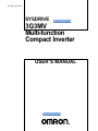
SYSDRIVE
3G3MV
Multi-function
Compact Inverter
USER’S MANUAL
USER’S MANUAL
SYSDRIVE 3G3MV
SERIES
Multi-function Compact Inverter
Thank you for choosing this SYSDRIVE 3G3MV-series product. Proper use
and handling of the product will ensure proper product performance, will
lengthen product life, and may prevent possible accidents.
Please read this manual thoroughly and handle and operate the product
with care.
1. To ensure safe and proper use of the OMRON Inverters, please read this USER’S
MANUAL (Cat. No. I527-E1) to gain sufficient knowledge of the devices, safety information, and precautions before actual use.
2. The products are illustrated without covers and shieldings for closer look in this
USER’S MANUAL. For actual use of the products, make sure to use the covers and
shieldings as specified.
3. This USER’S MANUAL and other related user’s manuals are to be delivered to the
actual end users of the products.
4. Please keep this manual close at hand for future reference.
5. If the product has been left unused for a long time, please inquire at our sales representative.
NOTICE
1. This manual describes the functions of the product and relations with other
products. You should assume that anything not described in this manual is
not possible.
2. Although care has been given in documenting the product, please contact your
OMRON representative if you have any suggestions on improving this manual.
3. The product contains potentially dangerous parts under the cover. Do not attempt
to open the cover under any circumstances. Doing so may result in injury or death
and may damage the product. Never attempt to repair or disassemble the product.
4. We recommend that you add the following precautions to any instruction manuals
you prepare for the system into which the product is being installed.
S Precautions on the dangers of high-voltage equipment.
S Precautions on touching the terminals of the product even after power has been
turned off. (These terminals are live even with the power turned off.)
5. Specifications and functions may be changed without notice in order to improve
product performance.
Items to Check Before Unpacking
Check the following items before removing the product from the package:
S Has the correct product been delivered (i.e., the correct model number and specifications)?
S Has the product been damaged in shipping?
S Are any screws or bolts loose?
Notice:
OMRON products are manufactured for use according to proper procedures by a qualified
operator and only for the purposes described in this manual.
The following conventions are used to indicate and classify precautions in this manual.
Always heed the information provided with them. Failure to heed precautions can result in
injury to people or damage to property.
!
DANGER
Indicates an imminently hazardous situation which, if not avoided, will result in death
or serious injury. Additionally, there may be severe property damage.
!
WARNING
Indicates a potentially hazardous situation which, if not avoided, could result in death
or serious injury. Additionally, there may be severe property damage.
! Caution
Indicates a potentially hazardous situation which, if not avoided, may result in minor
or moderate injury, or property damage.
OMRON Product References
All OMRON products are capitalized in this manual. The word “Unit” is also capitalized when
it refers to an OMRON product, regardless of whether or not it appears in the proper name
of the product.
The abbreviation “Ch,” which appears in some displays and on some OMRON products,
often means “word” and is abbreviated “Wd” in documentation in this sense.
The abbreviation “PLC” means Programmable Controller.
Visual Aids
The following headings appear in the left column of the manual to help you locate different
types of information.
Note Indicates information of particular interest for efficient and convenient operation of the product.
© OMRON, 1999
All rights reserved. No part of this publication may be reproduced, stored in a retrieval system, or transmitted,
in any form, or by any means, mechanical, electronic, photocopying, recording, or otherwise, without the prior
written permission of OMRON.
No patent liability is assumed with respect to the use of the information contained herein. Moreover, because
OMRON is constantly striving to improve its high-quality products, the information contained in this manual
is subject to change without notice. Every precaution has been taken in the preparation of this manual. Nevertheless, OMRON assumes no responsibility for errors or omissions. Neither is any liability assumed for damages resulting from the use of the information contained in this publication.
General Precautions
Observe the following precautions when using the SYSDRIVE Inverters and peripheral
devices.
This manual may include illustrations of the product with protective covers removed in order
to describe the components of the product in detail. Make sure that these protective covers
are on the product before use.
Consult your OMRON representative when using the product after a long period of storage.
!
WARNING
Do not touch the inside of the Inverter. Doing so may result in electrical shock.
!
WARNING
Operation, maintenance, or inspection must be performed after turning OFF the
power supply, confirming that the CHARGE indicator (or status indicators) are OFF,
and after waiting for the time specified on the front cover. Not doing so may result in
electrical shock.
!
WARNING
Do not damage, pull on, apply stress to, place heavy objects on, or pinch the cables.
Doing so may result in electrical shock.
!
WARNING
Do not touch the rotating parts of the motor under operation. Doing so may result in
injury.
!
WARNING
Do not modify the product. Doing so may result in injury or damage to the product.
! Caution
Do not store, install, or operate the product in the following places. Doing so may
result in electrical shock, fire or damage to the product.
S Locations subject to direct sunlight.
S Locations subject to temperatures or humidity outside the range specified in the
specifications.
S Locations subject to condensation as the result of severe changes in temperature.
S Locations subject to corrosive or flammable gases.
S Locations subject to exposure to combustibles.
S Locations subject to dust (especially iron dust) or salts.
S Locations subject to exposure to water, oil, or chemicals.
S Locations subject to shock or vibration.
! Caution
Do not touch the Inverter radiator, regenerative resistor, or Servomotor while the
power is being supplied or soon after the power is turned OFF. Doing so may result in
a skin burn due to the hot surface.
! Caution
Do not conduct a dielectric strength test on any part of the Inverter. Doing so may
result in damage to the product or malfunction.
! Caution
Take appropriate and sufficient countermeasures when installing systems in the following locations. Not doing so may result in equipment damage.
S Locations subject to static electricity or other forms of noise.
S Locations subject to strong electromagnetic fields and magnetic fields.
S Locations subject to possible exposure to radioactivity.
S Locations close to power supplies.
Transportation Precautions
! Caution
Do not hold by front cover or panel , instead, hold by the radiation fin (heat sink) while
transporting the product. Doing so may result in injury.
! Caution
Do not pull on the cables. Doing so may result in damage to the product or malfunction.
! Caution
Use the eye-bolts only for transporting the Inverter. Using them for transporting the
machinery may result in injury or malfunction.
Installation Precautions
!
WARNING
Provide an appropriate stopping device on the machine side to secure safety. (A
holding brake is not a stopping device for securing safety.) Not doing so may result in
injury.
!
WARNING
Provide an external emergency stopping device that allows an instantaneous stop of
operation and power interruption. Not doing so may result in injury.
! Caution
Be sure to install the product in the correct direction and provide specified clearances between the Inverter and control panel or with other devices. Not doing so
may result in fire or malfunction.
! Caution
Do not allow foreign objects to enter inside the product. Doing so may result in fire or
malfunction.
! Caution
Do not apply any strong impact. Doing so may result in damage to the product or
malfunction.
Wiring Precautions
!
WARNING
Wiring must be performed only after confirming that the power supply has been
turned OFF. Not doing so may result in electrical shock.
!
WARNING
Wiring must be performed by authorized personnel. Not doing so may result in
electrical shock or fire.
!
WARNING
Be sure to confirm operation only after wiring the emergency stop circuit. Not doing
so may result in injury.
!
WARNING
Always connect the ground terminals to a ground of 100 Ω or less for the 200-V AC
class, or 10 Ω or less for the 400-V AC class. Not connecting to a proper ground may
result in electrical shock.
! Caution
Install external breakers and take other safety measures against short-circuiting in
external wiring. Not doing so may result in fire.
! Caution
Confirm that the rated input voltage of the Inverter is the same as the AC power supply voltage. An incorrect power supply may result in fire, injury, or malfunction.
! Caution
Connect the Braking Resistor and Braking Resistor Unit as specified in the manual.
Not doing so may result in fire.
! Caution
Be sure to wire correctly and securely. Not doing so may result in injury or damage to
the product.
! Caution
Be sure to firmly tighten the screws on the terminal block. Not doing so may result in
fire, injury, or damage to the product.
! Caution
Do not connect an AC power to the U, V, or W output. Doing so may result in damage
to the product or malfunction.
! Caution
The motor may start operation if input terminal S2 is turned ON with the default
parameter settings. Wire terminals with NC contacts (e.g., 3-wire sequences) only
after setting the multi-function input parameters.
Operation and Adjustment Precautions
!
WARNING
Turn ON the input power supply only after mounting the front cover, terminal covers,
bottom cover, Operator, and optional items. Not doing so may result in electrical
shock.
!
WARNING
Do not remove the front cover, terminal covers, bottom cover, Operator, or optional
items while the power is being supplied. Not doing so may result in electrical shock or
damage to the product.
!
WARNING
Do not operate the Operator or switches with wet hands. Doing so may result in
electrical shock.
!
WARNING
Do not touch the inside of the Inverter. Doing so may result in electrical shock.
!
WARNING
Do not come close to the machine when using the error retry function because the
machine may abruptly start when stopped by an alarm. Doing so may result in injury.
!
WARNING
Do not come close to the machine immediately after resetting momentary power
interruption to avoid an unexpected restart (if operation is set to be continued in the
processing selection function after momentary power interruption is reset). Doing so
may result in injury.
!
WARNING
Provide a separate emergency stop switch because the STOP Key on the Operator
is valid only when function settings are performed. Not doing so may result in injury.
!
WARNING
Be sure confirm that the RUN signal is turned OFF before turning ON the power
supply, resetting the alarm, or switching the LOCAL/REMOTE selector. Doing so
while the RUN signal is turned ON may result in injury.
! Caution
Be sure to confirm permissible ranges of motors and machines before operation
because the Inverter speed can be easily changed from low to high. Not doing so
may result in damage to the product.
! Caution
Provide a separate holding brake when necessary. Not doing so may result in injury.
! Caution
Do not perform a signal check during operation. Doing so may result in injury or damage to the product.
! Caution
Do not carelessly change settings. Doing so may result in injury or damage to the
product.
Maintenance and Inspection Precautions
!
WARNING
Do not touch the Inverter terminals while the power is being supplied.
!
WARNING
Maintenance or inspection must be performed only after turning OFF the power
supply, confirming that the CHARGE indicator (or status indicators) is turned OFF,
and after waiting for the time specified on the front cover. Not doing so may result in
electrical shock.
!
WARNING
Maintenance, inspection, or parts replacement must be performed by authorized
personnel. Not doing so may result in electrical shock or injury.
!
WARNING
Do not attempt to take the Unit apart or repair. Doing either of these may result in
electrical shock or injury.
! Caution
Carefully handle the Inverter because it uses semiconductor elements. Careless
handling may result in malfunction.
! Caution
Do not change wiring, disconnect connectors, the Operator, or optional items, or
replace fans while power is being supplied. Doing so may result in injury, damage to
the product, or malfunction.
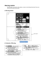
Warning Labels
Warning labels are pasted on the product as shown in the following illustration. Be sure to
follow the instructions given there.
H Warning Labels
Warning label
H Contents of Warning
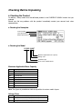
Checking Before Unpacking
H Checking the Product
On delivery, always check that the delivered product is the SYSDRIVE 3G3MV Inverter that you
ordered.
Should you find any problems with the product, immediately contact your nearest local sales
representative.
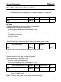
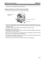
D Checking the Nameplate
Inverter model
Input specifications
Output specifications
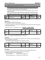
D Checking the Model
3G3MV-A4007
Maximum applicable motor capacity
Voltage class
Installation type
Series name: 3G3MV Series
Maximum Applicable Motor Capacity
001
002
004
007
015
022
037
055
075
0.1 (0.1) kW
0.25/0.37 (0.2) kW
0.55 (0.4) kW
1.1 (0.75) kW
1.5 (1.5) kW
2.2 (2.2) kW
3.7 (3.7) kW
5.5 (5.5) kW
7.5 (7.5) kW
Note The figures in parentheses indicate capacities for motors used in Japan.
Voltage Class
2
B
4
Three-phase 200-V AC input (200-V class)
Single-phase 200-V AC input (200-V class)
Three-phase 400-V AC input (400-V class)
Installation Type
A
C
Panel-mounting (IP10 min.) or closed wall-mounting models
Closed wall-mounting models
(NEMA1 type for North America)
Note A-type models with 5.5-KW and 7.5-KW capacity also have NEMA1 enclosure ratings.
D Checking for Damage
Check the overall appearance and check for damage or scratches resulting from transportation.
H Checking the Accessories
Note that this manual is the only accessory provided with the 3G3MV. Set screws and other necessary
parts must be provided by the user.
Read and Understand this Manual
Please read and understand this manual before using the product. Please consult your OMRON
representative if you have any questions or comments.
Warranty and Limitations of Liability
WARRANTY
OMRON’s exclusive warranty is that the products are free from defects in materials and workmanship for
a period of one year (or other period if specified) from date of sale by OMRON.
OMRON MAKES NO WARRANTY OR REPRESENTATION, EXPRESS OR IMPLIED, REGARDING
NON-INFRINGEMENT, MERCHANTABILITY, OR FITNESS FOR PARTICULAR PURPOSE OF THE
PRODUCTS. ANY BUYER OR USER ACKNOWLEDGES THAT THE BUYER OR USER ALONE HAS
DETERMINED THAT THE PRODUCTS WILL SUITABLY MEET THE REQUIREMENTS OF THEIR
INTENDED USE. OMRON DISCLAIMS ALL OTHER WARRANTIES, EXPRESS OR IMPLIED.
LIMITATIONS OF LIABILITY
OMRON SHALL NOT BE RESPONSIBLE FOR SPECIAL, INDIRECT, OR CONSEQUENTIAL
DAMAGES, LOSS OF PROFITS OR COMMERCIAL LOSS IN ANY WAY CONNECTED WITH THE
PRODUCTS, WHETHER SUCH CLAIM IS BASED ON CONTRACT, WARRANTY, NEGLIGENCE, OR
STRICT LIABILITY.
In no event shall the responsibility of OMRON for any act exceed the individual price of the product on
which liability is asserted.
IN NO EVENT SHALL OMRON BE RESPONSIBLE FOR WARRANTY, REPAIR, OR OTHER CLAIMS
REGARDING THE PRODUCTS UNLESS OMRON’S ANALYSIS CONFIRMS THAT THE PRODUCTS
WERE PROPERLY HANDLED, STORED, INSTALLED, AND MAINTAINED AND NOT SUBJECT TO
CONTAMINATION, ABUSE, MISUSE, OR INAPPROPRIATE MODIFICATION OR REPAIR.
Application Considerations
SUITABILITY FOR USE
OMRON shall not be responsible for conformity with any standards, codes, or regulations that apply to
the combination of products in the customer’s application or use of the products.
At the customer’s request, OMRON will provide applicable third party certification documents identifying
ratings and limitations of use that apply to the products. This information by itself is not sufficient for a
complete determination of the suitability of the products in combination with the end product, machine,
system, or other application or use.
The following are some examples of applications for which particular attention must be given. This is not
intended to be an exhaustive list of all possible uses of the products, nor is it intended to imply that the
uses listed may be suitable for the products:
• Outdoor use, uses involving potential chemical contamination or electrical interference, or conditions
or uses not described in this manual.
• Nuclear energy control systems, combustion systems, railroad systems, aviation systems, medical
equipment, amusement machines, vehicles, safety equipment, and installations subject to separate
industry or government regulations.
• Systems, machines, and equipment that could present a risk to life or property.
Please know and observe all prohibitions of use applicable to the products.
NEVER USE THE PRODUCTS FOR AN APPLICATION INVOLVING SERIOUS RISK TO LIFE OR
PROPERTY WITHOUT ENSURING THAT THE SYSTEM AS A WHOLE HAS BEEN DESIGNED TO
ADDRESS THE RISKS, AND THAT THE OMRON PRODUCTS ARE PROPERLY RATED AND
INSTALLED FOR THE INTENDED USE WITHIN THE OVERALL EQUIPMENT OR SYSTEM.
PROGRAMMABLE PRODUCTS
OMRON shall not be responsible for the user’s programming of a programmable product, or any
consequence thereof.
Disclaimers
CHANGE IN SPECIFICATIONS
Product specifications and accessories may be changed at any time based on improvements and other
reasons.
It is our practice to change model numbers when published ratings or features are changed, or when
significant construction changes are made. However, some specifications of the products may be
changed without any notice. When in doubt, special model numbers may be assigned to fix or establish
key specifications for your application on your request. Please consult with your OMRON representative
at any time to confirm actual specifications of purchased products.
DIMENSIONS AND WEIGHTS
Dimensions and weights are nominal and are not to be used for manufacturing purposes, even when
tolerances are shown.
PERFORMANCE DATA
Performance data given in this manual is provided as a guide for the user in determining suitability and
does not constitute a warranty. It may represent the result of OMRON’s test conditions, and the users
must correlate it to actual application requirements. Actual performance is subject to the OMRON
Warranty and Limitations of Liability.
ERRORS AND OMISSIONS
The information in this manual has been carefully checked and is believed to be accurate; however, no
responsibility is assumed for clerical, typographical, or proofreading errors, or omissions.
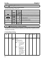
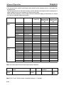
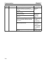
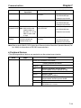
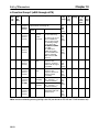
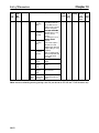
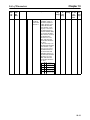
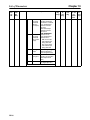
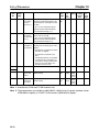
About this Manual
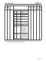
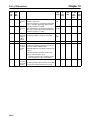
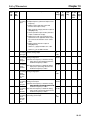
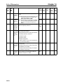
This manual is divided into the chapters described in the following table. Information is organized by
application area to enable you to use the manual more efficiently.
Chapter
Chapter 1 Overview
Chapter 2 Design
Chapter 3 Preparing for Operation
and Monitoring
Chapter 4 Test Run
Chapter 5 Basic Operation
Chapter 6 Advanced Operation
Chapter 7 Communications
Chapter 8 Maintenance Operations
Chapter 9 Specifications
Chapter 10 List of Parameters
Chapter 11 Using the Inverter for a
Motor
Contents
Describes features and nomenclature.
Provides dimensions, installation methods, wiring methods, peripheral
device design information, and peripheral device selection information.
Describes nomenclature and Digital Operator procedures for operating
and monitoring Inverters. Data copying and other functions are
described.
Describes the method for controlling a motor through the frequency
adjuster on the front of the Inverter. This can be used for trial
operation of the system.
Describes basic Inverter control functions for users not familiar with
Inverters. The functions that must be understood to drive a motor with
an Inverter are described.
Describes all of the functions provided by the Inverter. These functions
will enable more advanced applications, and includes functions that
will improve motor control through the Inverter, such as
responsiveness (torque characteristics), increasing speed accuracy,
PID control, overtorque detection, and other functions.
Describes the general-purpose RS-422/RS-485 communications
functions provided by the Inverter, including connection methods and
sample programming for SYSMAC Programmable Controllers.
Provides maintenance, inspection, and troubleshooting information.
Provides Inverter specifications, as well as the specifications and
dimensions of peripheral devices.
Lists basic information on Inverter parameters as a reference for users
already familiar with Inverter operation. Parameters are listed in order
with the page numbers of further information for easy reference.
Describes information on using the Inverter for a motor.
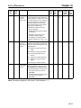
Terms and Conditions of Sale
1. Offer; Acceptance. These terms and conditions (these "Terms") are deemed
part of all quotes, agreements, purchase orders, acknowledgments, price lists,
catalogs, manuals, brochures and other documents, whether electronic or in
writing, relating to the sale of products or services (collectively, the "Products")
by Omron Electronics LLC and its subsidiary companies (“Omron”). Omron
objects to any terms or conditions proposed in Buyer’s purchase order or other
documents which are inconsistent with, or in addition to, these Terms.
2. Prices; Payment Terms. All prices stated are current, subject to change without notice by Omron. Omron reserves the right to increase or decrease prices
on any unshipped portions of outstanding orders. Payments for Products are
due net 30 days unless otherwise stated in the invoice.
3. Discounts. Cash discounts, if any, will apply only on the net amount of invoices
sent to Buyer after deducting transportation charges, taxes and duties, and will
be allowed only if (i) the invoice is paid according to Omron’s payment terms
and (ii) Buyer has no past due amounts.
4. Interest. Omron, at its option, may charge Buyer 1-1/2% interest per month or
the maximum legal rate, whichever is less, on any balance not paid within the
stated terms.
5. Orders. Omron will accept no order less than $200 net billing.
6. Governmental Approvals. Buyer shall be responsible for, and shall bear all
costs involved in, obtaining any government approvals required for the importation or sale of the Products.
7. Taxes. All taxes, duties and other governmental charges (other than general
real property and income taxes), including any interest or penalties thereon,
imposed directly or indirectly on Omron or required to be collected directly or
indirectly by Omron for the manufacture, production, sale, delivery, importation, consumption or use of the Products sold hereunder (including customs
duties and sales, excise, use, turnover and license taxes) shall be charged to
and remitted by Buyer to Omron.
8. Financial. If the financial position of Buyer at any time becomes unsatisfactory
to Omron, Omron reserves the right to stop shipments or require satisfactory
security or payment in advance. If Buyer fails to make payment or otherwise
comply with these Terms or any related agreement, Omron may (without liability and in addition to other remedies) cancel any unshipped portion of Products sold hereunder and stop any Products in transit until Buyer pays all
amounts, including amounts payable hereunder, whether or not then due,
which are owing to it by Buyer. Buyer shall in any event remain liable for all
unpaid accounts.
9. Cancellation; Etc. Orders are not subject to rescheduling or cancellation
unless Buyer indemnifies Omron against all related costs or expenses.
10. Force Majeure. Omron shall not be liable for any delay or failure in delivery
resulting from causes beyond its control, including earthquakes, fires, floods,
strikes or other labor disputes, shortage of labor or materials, accidents to
machinery, acts of sabotage, riots, delay in or lack of transportation or the
requirements of any government authority.
11. Shipping; Delivery. Unless otherwise expressly agreed in writing by Omron:
a. Shipments shall be by a carrier selected by Omron; Omron will not drop ship
except in “break down” situations.
b. Such carrier shall act as the agent of Buyer and delivery to such carrier shall
constitute delivery to Buyer;
c. All sales and shipments of Products shall be FOB shipping point (unless otherwise stated in writing by Omron), at which point title and risk of loss shall
pass from Omron to Buyer; provided that Omron shall retain a security interest in the Products until the full purchase price is paid;
d. Delivery and shipping dates are estimates only; and
e. Omron will package Products as it deems proper for protection against normal handling and extra charges apply to special conditions.
12. Claims. Any claim by Buyer against Omron for shortage or damage to the
Products occurring before delivery to the carrier must be presented in writing
to Omron within 30 days of receipt of shipment and include the original transportation bill signed by the carrier noting that the carrier received the Products
from Omron in the condition claimed.
13. Warranties. (a) Exclusive Warranty. Omron’s exclusive warranty is that the
Products will be free from defects in materials and workmanship for a period of
twelve months from the date of sale by Omron (or such other period expressed
in writing by Omron). Omron disclaims all other warranties, express or implied.
(b) Limitations. OMRON MAKES NO WARRANTY OR REPRESENTATION,
EXPRESS OR IMPLIED, ABOUT NON-INFRINGEMENT, MERCHANTABIL-
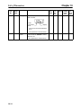
14.
15.
16.
17.
18.
ITY OR FITNESS FOR A PARTICULAR PURPOSE OF THE PRODUCTS.
BUYER ACKNOWLEDGES THAT IT ALONE HAS DETERMINED THAT THE
PRODUCTS WILL SUITABLY MEET THE REQUIREMENTS OF THEIR
INTENDED USE. Omron further disclaims all warranties and responsibility of
any type for claims or expenses based on infringement by the Products or otherwise of any intellectual property right. (c) Buyer Remedy. Omron’s sole obligation hereunder shall be, at Omron’s election, to (i) replace (in the form
originally shipped with Buyer responsible for labor charges for removal or
replacement thereof) the non-complying Product, (ii) repair the non-complying
Product, or (iii) repay or credit Buyer an amount equal to the purchase price of
the non-complying Product; provided that in no event shall Omron be responsible for warranty, repair, indemnity or any other claims or expenses regarding
the Products unless Omron’s analysis confirms that the Products were properly handled, stored, installed and maintained and not subject to contamination, abuse, misuse or inappropriate modification. Return of any Products by
Buyer must be approved in writing by Omron before shipment. Omron Companies shall not be liable for the suitability or unsuitability or the results from the
use of Products in combination with any electrical or electronic components,
circuits, system assemblies or any other materials or substances or environments. Any advice, recommendations or information given orally or in writing,
are not to be construed as an amendment or addition to the above warranty.
See http://oeweb.omron.com or contact your Omron representative for published information.
Limitation on Liability; Etc. OMRON COMPANIES SHALL NOT BE LIABLE
FOR SPECIAL, INDIRECT, INCIDENTAL, OR CONSEQUENTIAL DAMAGES,
LOSS OF PROFITS OR PRODUCTION OR COMMERCIAL LOSS IN ANY
WAY CONNECTED WITH THE PRODUCTS, WHETHER SUCH CLAIM IS
BASED IN CONTRACT, WARRANTY, NEGLIGENCE OR STRICT LIABILITY.
Further, in no event shall liability of Omron Companies exceed the individual
price of the Product on which liability is asserted.
Indemnities. Buyer shall indemnify and hold harmless Omron Companies and
their employees from and against all liabilities, losses, claims, costs and
expenses (including attorney's fees and expenses) related to any claim, investigation, litigation or proceeding (whether or not Omron is a party) which arises
or is alleged to arise from Buyer's acts or omissions under these Terms or in
any way with respect to the Products. Without limiting the foregoing, Buyer (at
its own expense) shall indemnify and hold harmless Omron and defend or settle any action brought against such Companies to the extent based on a claim
that any Product made to Buyer specifications infringed intellectual property
rights of another party.
Property; Confidentiality. Any intellectual property in the Products is the exclusive property of Omron Companies and Buyer shall not attempt to duplicate it
in any way without the written permission of Omron. Notwithstanding any
charges to Buyer for engineering or tooling, all engineering and tooling shall
remain the exclusive property of Omron. All information and materials supplied
by Omron to Buyer relating to the Products are confidential and proprietary,
and Buyer shall limit distribution thereof to its trusted employees and strictly
prevent disclosure to any third party.
Export Controls. Buyer shall comply with all applicable laws, regulations and
licenses regarding (i) export of products or information; (iii) sale of products to
“forbidden” or other proscribed persons; and (ii) disclosure to non-citizens of
regulated technology or information.
Miscellaneous. (a) Waiver. No failure or delay by Omron in exercising any right
and no course of dealing between Buyer and Omron shall operate as a waiver
of rights by Omron. (b) Assignment. Buyer may not assign its rights hereunder
without Omron's written consent. (c) Law. These Terms are governed by the
law of the jurisdiction of the home office of the Omron company from which
Buyer is purchasing the Products (without regard to conflict of law principles). (d) Amendment. These Terms constitute the entire agreement between
Buyer and Omron relating to the Products, and no provision may be changed
or waived unless in writing signed by the parties. (e) Severability. If any provision hereof is rendered ineffective or invalid, such provision shall not invalidate
any other provision. (f) Setoff. Buyer shall have no right to set off any amounts
against the amount owing in respect of this invoice. (g) Definitions. As used
herein, “including” means “including without limitation”; and “Omron Companies” (or similar words) mean Omron Corporation and any direct or indirect
subsidiary or affiliate thereof.
Certain Precautions on Specifications and Use
1. Suitability of Use. Omron Companies shall not be responsible for conformity
with any standards, codes or regulations which apply to the combination of the
Product in the Buyer’s application or use of the Product. At Buyer’s request,
Omron will provide applicable third party certification documents identifying
ratings and limitations of use which apply to the Product. This information by
itself is not sufficient for a complete determination of the suitability of the Product in combination with the end product, machine, system, or other application
or use. Buyer shall be solely responsible for determining appropriateness of
the particular Product with respect to Buyer’s application, product or system.
Buyer shall take application responsibility in all cases but the following is a
non-exhaustive list of applications for which particular attention must be given:
(i) Outdoor use, uses involving potential chemical contamination or electrical
interference, or conditions or uses not described in this document.
(ii) Use in consumer products or any use in significant quantities.
(iii) Energy control systems, combustion systems, railroad systems, aviation
systems, medical equipment, amusement machines, vehicles, safety equipment, and installations subject to separate industry or government regulations.
(iv) Systems, machines and equipment that could present a risk to life or property. Please know and observe all prohibitions of use applicable to this Product.
NEVER USE THE PRODUCT FOR AN APPLICATION INVOLVING SERIOUS
RISK TO LIFE OR PROPERTY OR IN LARGE QUANTITIES WITHOUT
ENSURING THAT THE SYSTEM AS A WHOLE HAS BEEN DESIGNED TO
2.
3.
4.
5.
ADDRESS THE RISKS, AND THAT THE OMRON’S PRODUCT IS PROPERLY RATED AND INSTALLED FOR THE INTENDED USE WITHIN THE
OVERALL EQUIPMENT OR SYSTEM.
Programmable Products. Omron Companies shall not be responsible for the
user’s programming of a programmable Product, or any consequence thereof.
Performance Data. Data presented in Omron Company websites, catalogs
and other materials is provided as a guide for the user in determining suitability and does not constitute a warranty. It may represent the result of Omron’s
test conditions, and the user must correlate it to actual application requirements. Actual performance is subject to the Omron’s Warranty and Limitations
of Liability.
Change in Specifications. Product specifications and accessories may be
changed at any time based on improvements and other reasons. It is our practice to change part numbers when published ratings or features are changed,
or when significant construction changes are made. However, some specifications of the Product may be changed without any notice. When in doubt, special part numbers may be assigned to fix or establish key specifications for
your application. Please consult with your Omron’s representative at any time
to confirm actual specifications of purchased Product.
Errors and Omissions. Information presented by Omron Companies has been
checked and is believed to be accurate; however, no responsibility is assumed
for clerical, typographical or proofreading errors or omissions.
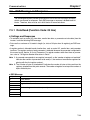
Table of Contents
Chapter 1. Overview . . . . . . . . . . . . . . . . . . . . . . . . . . . . . . . . . . . . . . . . 1-1
1-1 Functions . . . . . . . . . . . . . . . . . . . . . . . . . . . . . . . . . . . . . . . . . . . . . . . . . . . . . . . . . . . . . . . . . .
1-2 Nomenclature . . . . . . . . . . . . . . . . . . . . . . . . . . . . . . . . . . . . . . . . . . . . . . . . . . . . . . . . . . . . . . .
1-3 New Features . . . . . . . . . . . . . . . . . . . . . . . . . . . . . . . . . . . . . . . . . . . . . . . . . . . . . . . . . . . . . . .
1-2
1-5
1-8
Chapter 2. Design . . . . . . . . . . . . . . . . . . . . . . . . . . . . . . . . . . . . . . . . . . 2-1
2-1 Installation . . . . . . . . . . . . . . . . . . . . . . . . . . . . . . . . . . . . . . . . . . . . . . . . . . . . . . . . . . . . . . . . .
2-1-1 Dimensions . . . . . . . . . . . . . . . . . . . . . . . . . . . . . . . . . . . . . . . . . . . . . . . . . . . . . . . . . .
2-1-2 Installation Conditions . . . . . . . . . . . . . . . . . . . . . . . . . . . . . . . . . . . . . . . . . . . . . . . . .
2-1-3 Removing and Mounting the Covers . . . . . . . . . . . . . . . . . . . . . . . . . . . . . . . . . . . . . .
2-2 Wiring . . . . . . . . . . . . . . . . . . . . . . . . . . . . . . . . . . . . . . . . . . . . . . . . . . . . . . . . . . . . . . . . . . . .
2-2-1 Terminal Block . . . . . . . . . . . . . . . . . . . . . . . . . . . . . . . . . . . . . . . . . . . . . . . . . . . . . . .
2-2-2 Standard Connections . . . . . . . . . . . . . . . . . . . . . . . . . . . . . . . . . . . . . . . . . . . . . . . . . .
2-2-3 Wiring around the Main Circuit . . . . . . . . . . . . . . . . . . . . . . . . . . . . . . . . . . . . . . . . . .
2-2-4 Wiring Control Circuit Terminals . . . . . . . . . . . . . . . . . . . . . . . . . . . . . . . . . . . . . . . . .
2-2-5 Conforming to EC Directives . . . . . . . . . . . . . . . . . . . . . . . . . . . . . . . . . . . . . . . . . . . .
2-2
2-2
2-6
2-8
2-11
2-12
2-20
2-21
2-34
2-36
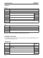
Chapter 3. Preparing for Operation and Monitoring . . . . . . . . . . . . . 3-1
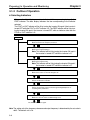
3-1 Nomenclature . . . . . . . . . . . . . . . . . . . . . . . . . . . . . . . . . . . . . . . . . . . . . . . . . . . . . . . . . . . . . . .
3-1-1 Names of Parts and their Functions . . . . . . . . . . . . . . . . . . . . . . . . . . . . . . . . . . . . . . .
3-1-2 Outline of Operation . . . . . . . . . . . . . . . . . . . . . . . . . . . . . . . . . . . . . . . . . . . . . . . . . . .
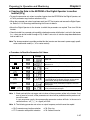
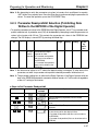
3-2 Parameter Copy and Verify Function . . . . . . . . . . . . . . . . . . . . . . . . . . . . . . . . . . . . . . . . . . . .
3-2-1 Parameter for Copying and Verifying Set Values . . . . . . . . . . . . . . . . . . . . . . . . . . . . .
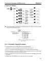
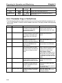
3-2-2 Parameter Copying Procedure . . . . . . . . . . . . . . . . . . . . . . . . . . . . . . . . . . . . . . . . . . .
3-2-3 Parameter Read-prohibit Selection (Prohibiting Data Written to the EEPROM of
the Digital Operator) . . . . . . . . . . . . . . . . . . . . . . . . . . . . . . . . . . . . . . . . . . . . . . . . . . .
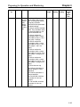
3-2-4 Parameter Copy or Verify Errors . . . . . . . . . . . . . . . . . . . . . . . . . . . . . . . . . . . . . . . . .
3-2
3-2
3-4
3-10
3-10
3-11
3-17
3-18
Chapter 4. Test Run . . . . . . . . . . . . . . . . . . . . . . . . . . . . . . . . . . . . . . . . 4-1
4-1 Procedure for Test Run . . . . . . . . . . . . . . . . . . . . . . . . . . . . . . . . . . . . . . . . . . . . . . . . . . . . . . .
4-2 Operation Example . . . . . . . . . . . . . . . . . . . . . . . . . . . . . . . . . . . . . . . . . . . . . . . . . . . . . . . . . .
4-3
4-5
Chapter 5. Basic Operation . . . . . . . . . . . . . . . . . . . . . . . . . . . . . . . . . . 5-1
5-1 Initial Settings . . . . . . . . . . . . . . . . . . . . . . . . . . . . . . . . . . . . . . . . . . . . . . . . . . . . . . . . . . . . . .
5-1-1 Setting the Parameter Write-prohibit Selection/Parameter Initialization (n001) . . . .
5-1-2 Setting the Control Mode (n002) . . . . . . . . . . . . . . . . . . . . . . . . . . . . . . . . . . . . . . . . .
5-2 Operation in Vector Control . . . . . . . . . . . . . . . . . . . . . . . . . . . . . . . . . . . . . . . . . . . . . . . . . . .
5-3 Operation in V/f Control . . . . . . . . . . . . . . . . . . . . . . . . . . . . . . . . . . . . . . . . . . . . . . . . . . . . . .
5-3-1 Setting the Rated Motor Current (n036) . . . . . . . . . . . . . . . . . . . . . . . . . . . . . . . . . . . .
5-3-2 Setting the V/f Patterns (n011 to n017) . . . . . . . . . . . . . . . . . . . . . . . . . . . . . . . . . . . .
5-4 Setting the Local/Remote Mode . . . . . . . . . . . . . . . . . . . . . . . . . . . . . . . . . . . . . . . . . . . . . . . .
5-5 Selecting the Operation Command . . . . . . . . . . . . . . . . . . . . . . . . . . . . . . . . . . . . . . . . . . . . . .
5-6 Setting the Frequency Reference . . . . . . . . . . . . . . . . . . . . . . . . . . . . . . . . . . . . . . . . . . . . . . . .
5-6-1 Selecting the Frequency Reference . . . . . . . . . . . . . . . . . . . . . . . . . . . . . . . . . . . . . . .
5-6-2 Upper and Lower Frequency Reference Limits . . . . . . . . . . . . . . . . . . . . . . . . . . . . . .
5-6-3 Frequency Referencing by Analog Input . . . . . . . . . . . . . . . . . . . . . . . . . . . . . . . . . . .
5-6-4 Setting Frequency References through Key Sequences . . . . . . . . . . . . . . . . . . . . . . . .
5-6-5 Setting Frequency References by Pulse Train Input . . . . . . . . . . . . . . . . . . . . . . . . . .
5-2
5-2
5-3
5-5
5-7
5-7
5-7
5-9
5-10
5-11
5-11
5-12
5-13
5-18
5-23
Table of Contents
5-7
5-8
5-9
5-10
Setting the Acceleration/Deceleration Time . . . . . . . . . . . . . . . . . . . . . . . . . . . . . . . . . . . . . . .
Selecting the Reverse Rotation-prohibit . . . . . . . . . . . . . . . . . . . . . . . . . . . . . . . . . . . . . . . . . .
Selecting the Stopping Method . . . . . . . . . . . . . . . . . . . . . . . . . . . . . . . . . . . . . . . . . . . . . . . . .
Multi-function I/O . . . . . . . . . . . . . . . . . . . . . . . . . . . . . . . . . . . . . . . . . . . . . . . . . . . . . . . . . . .
5-10-1 Multi-function Input . . . . . . . . . . . . . . . . . . . . . . . . . . . . . . . . . . . . . . . . . . . . . . . . . . .
5-10-2 Multi-function Output . . . . . . . . . . . . . . . . . . . . . . . . . . . . . . . . . . . . . . . . . . . . . . . . . .
5-11 Multi-function Analog Output and Pulse Monitor Output . . . . . . . . . . . . . . . . . . . . . . . . . . . .
5-11-1 Setting the Multi-function Analog Output (n065 through n067) . . . . . . . . . . . . . . . . .
5-11-2 Setting the Pulse Monitor Output (n065 and n150) . . . . . . . . . . . . . . . . . . . . . . . . . . .
5-25
5-28
5-29
5-30
5-30
5-36
5-38
5-38
5-39
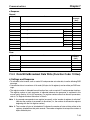
Chapter 6. Advanced Operation . . . . . . . . . . . . . . . . . . . . . . . . . . . . . . 6-1
6-1 Precise Vector Control Settings and Adjustments . . . . . . . . . . . . . . . . . . . . . . . . . . . . . . . . . . .
6-1-1 Precise Vector Control Settings . . . . . . . . . . . . . . . . . . . . . . . . . . . . . . . . . . . . . . . . . .
6-1-2 Adjusting Output Torque in Vector Control . . . . . . . . . . . . . . . . . . . . . . . . . . . . . . . . .
6-2 Energy-saving Control . . . . . . . . . . . . . . . . . . . . . . . . . . . . . . . . . . . . . . . . . . . . . . . . . . . . . . . .
6-2-1 Energy-saving Control Operation . . . . . . . . . . . . . . . . . . . . . . . . . . . . . . . . . . . . . . . . .
6-2-2 Performing Energy-saving Settings . . . . . . . . . . . . . . . . . . . . . . . . . . . . . . . . . . . . . . .
6-3 PID Control . . . . . . . . . . . . . . . . . . . . . . . . . . . . . . . . . . . . . . . . . . . . . . . . . . . . . . . . . . . . . . . .
6-3-1 PID Control Applications . . . . . . . . . . . . . . . . . . . . . . . . . . . . . . . . . . . . . . . . . . . . . . .
6-3-2 PID Control Operation . . . . . . . . . . . . . . . . . . . . . . . . . . . . . . . . . . . . . . . . . . . . . . . . .
6-3-3 Types of PID Control . . . . . . . . . . . . . . . . . . . . . . . . . . . . . . . . . . . . . . . . . . . . . . . . . .
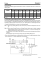
6-3-4 Block Diagram of PID Control . . . . . . . . . . . . . . . . . . . . . . . . . . . . . . . . . . . . . . . . . . .
6-3-5 Input Selection of PID Control Target Value and Detection Value . . . . . . . . . . . . . . .
6-3-6 PID Control Settings . . . . . . . . . . . . . . . . . . . . . . . . . . . . . . . . . . . . . . . . . . . . . . . . . . .
6-3-7 PID Adjustments . . . . . . . . . . . . . . . . . . . . . . . . . . . . . . . . . . . . . . . . . . . . . . . . . . . . . .
6-3-8 PID Fine Tuning . . . . . . . . . . . . . . . . . . . . . . . . . . . . . . . . . . . . . . . . . . . . . . . . . . . . . .
6-4 Setting the Carrier Frequency . . . . . . . . . . . . . . . . . . . . . . . . . . . . . . . . . . . . . . . . . . . . . . . . . .
6-5 DC Injection Braking Function . . . . . . . . . . . . . . . . . . . . . . . . . . . . . . . . . . . . . . . . . . . . . . . . .
6-6 Stall Prevention Function . . . . . . . . . . . . . . . . . . . . . . . . . . . . . . . . . . . . . . . . . . . . . . . . . . . . .
6-7 Overtorque/Undertorque Detection Function . . . . . . . . . . . . . . . . . . . . . . . . . . . . . . . . . . . . . .
6-8 Torque Compensation Function . . . . . . . . . . . . . . . . . . . . . . . . . . . . . . . . . . . . . . . . . . . . . . . . .
6-9 Slip Compensation Function . . . . . . . . . . . . . . . . . . . . . . . . . . . . . . . . . . . . . . . . . . . . . . . . . . .
6-10 Other Functions . . . . . . . . . . . . . . . . . . . . . . . . . . . . . . . . . . . . . . . . . . . . . . . . . . . . . . . . . . . . .
6-10-1 Digital Operator Disconnection Error Detection . . . . . . . . . . . . . . . . . . . . . . . . . . . . .
6-10-2 Motor Protection Functions (n037 and n038) . . . . . . . . . . . . . . . . . . . . . . . . . . . . . . . .
6-10-3 Cooling Fan Operation Function (n039) . . . . . . . . . . . . . . . . . . . . . . . . . . . . . . . . . . .
6-10-4 Momentary Power Interruption Compensation (n081) . . . . . . . . . . . . . . . . . . . . . . . .
6-10-5 Fault Retry (n082) . . . . . . . . . . . . . . . . . . . . . . . . . . . . . . . . . . . . . . . . . . . . . . . . . . . . .
6-10-6 Frequency Jump Function (n083 to n086) . . . . . . . . . . . . . . . . . . . . . . . . . . . . . . . . . .
6-10-7 Accumulated Operating Time (n087, n088) . . . . . . . . . . . . . . . . . . . . . . . . . . . . . . . . .
6-10-8 Frequency Detection . . . . . . . . . . . . . . . . . . . . . . . . . . . . . . . . . . . . . . . . . . . . . . . . . . .
6-10-9 UP/DOWN Command Frequency Memory (n100) . . . . . . . . . . . . . . . . . . . . . . . . . . .
6-10-10 Input Open-phase Detection (n166, n167) . . . . . . . . . . . . . . . . . . . . . . . . . . . . . . . . .
6-10-11 Output Open-phase Detection (n168, n169) . . . . . . . . . . . . . . . . . . . . . . . . . . . . . . . .
6-10-12 Fault Log (n178) . . . . . . . . . . . . . . . . . . . . . . . . . . . . . . . . . . . . . . . . . . . . . . . . . . . . .
6-2
6-2
6-3
6-5
6-5
6-6
6-11
6-11
6-12
6-12
6-14
6-15
6-16
6-19
6-21
6-23
6-26
6-27
6-31
6-35
6-37
6-39
6-39
6-39
6-40
6-40
6-41
6-42
6-43
6-44
6-45
6-47
6-47
6-48
Table of Contents
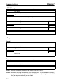
Chapter 7. Communications . . . . . . . . . . . . . . . . . . . . . . . . . . . . . . . . . . 7-1
7-1 Inverter Settings . . . . . . . . . . . . . . . . . . . . . . . . . . . . . . . . . . . . . . . . . . . . . . . . . . . . . . . . . . . . .
7-1-1 Setting the Communications Conditions . . . . . . . . . . . . . . . . . . . . . . . . . . . . . . . . . . .
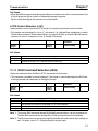
7-1-2 RUN Command Selection (n003) . . . . . . . . . . . . . . . . . . . . . . . . . . . . . . . . . . . . . . . . .
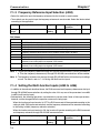
7-1-3 Frequency Reference Input Selection (n004) . . . . . . . . . . . . . . . . . . . . . . . . . . . . . . . .
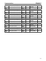
7-1-4 Setting the Multi-function Inputs (n050 to n056) . . . . . . . . . . . . . . . . . . . . . . . . . . . .
7-2 Message Communications Basic Format . . . . . . . . . . . . . . . . . . . . . . . . . . . . . . . . . . . . . . . . .
7-3 DSR Message and Response . . . . . . . . . . . . . . . . . . . . . . . . . . . . . . . . . . . . . . . . . . . . . . . . . . .
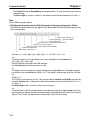
7-3-1 Data Read (Function Code: 03 Hex) . . . . . . . . . . . . . . . . . . . . . . . . . . . . . . . . . . . . . .
7-3-2 Data Write/Broadcast Data Write (Function Code: 10 Hex) . . . . . . . . . . . . . . . . . . . .
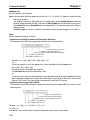
7-3-3 Loop-back Test (Function Code: 08 Hex) . . . . . . . . . . . . . . . . . . . . . . . . . . . . . . . . . .
7-4 Enter Command . . . . . . . . . . . . . . . . . . . . . . . . . . . . . . . . . . . . . . . . . . . . . . . . . . . . . . . . . . . . .
7-5 Setting the Communications Data . . . . . . . . . . . . . . . . . . . . . . . . . . . . . . . . . . . . . . . . . . . . . . .
7-6 Register Number Allocations in Detail . . . . . . . . . . . . . . . . . . . . . . . . . . . . . . . . . . . . . . . . . . .
7-6-1 I/O Function . . . . . . . . . . . . . . . . . . . . . . . . . . . . . . . . . . . . . . . . . . . . . . . . . . . . . . . . .
7-6-2 Monitor Functions . . . . . . . . . . . . . . . . . . . . . . . . . . . . . . . . . . . . . . . . . . . . . . . . . . . . .
7-7 Communications Error Codes . . . . . . . . . . . . . . . . . . . . . . . . . . . . . . . . . . . . . . . . . . . . . . . . . .
7-8 Self-diagnostic Test . . . . . . . . . . . . . . . . . . . . . . . . . . . . . . . . . . . . . . . . . . . . . . . . . . . . . . . . . .
7-9 Communications with Programmable Controller . . . . . . . . . . . . . . . . . . . . . . . . . . . . . . . . . . .
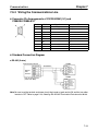
7-9-1 Available Programmable Controllers and Peripheral Devices . . . . . . . . . . . . . . . . . . .
7-9-2 Wiring the Communications Line . . . . . . . . . . . . . . . . . . . . . . . . . . . . . . . . . . . . . . . .
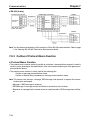
7-9-3 Outline of Protocol Macro Function . . . . . . . . . . . . . . . . . . . . . . . . . . . . . . . . . . . . . . .
7-9-4 Creating a Project File . . . . . . . . . . . . . . . . . . . . . . . . . . . . . . . . . . . . . . . . . . . . . . . . .
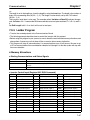
7-9-5 Ladder Program . . . . . . . . . . . . . . . . . . . . . . . . . . . . . . . . . . . . . . . . . . . . . . . . . . . . . .
7-9-6 Communications Response Time . . . . . . . . . . . . . . . . . . . . . . . . . . . . . . . . . . . . . . . . .
7-2
7-2
7-5
7-6
7-6
7-8
7-11
7-11
7-13
7-16
7-18
7-19
7-21
7-21
7-22
7-27
7-29
7-30
7-30
7-33
7-34
7-38
7-47
7-51
Chapter 8. Maintenance Operations . . . . . . . . . . . . . . . . . . . . . . . . . . . 8-1
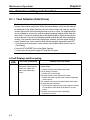
8-1 Protective and Diagnostic Functions . . . . . . . . . . . . . . . . . . . . . . . . . . . . . . . . . . . . . . . . . . . . .
8-1-1 Fault Detection (Fatal Errors) . . . . . . . . . . . . . . . . . . . . . . . . . . . . . . . . . . . . . . . . . . . .
8-1-2 Warning Detection (Nonfatal Errors) . . . . . . . . . . . . . . . . . . . . . . . . . . . . . . . . . . . . . .
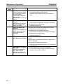
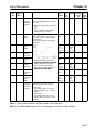
8-2 Troubleshooting . . . . . . . . . . . . . . . . . . . . . . . . . . . . . . . . . . . . . . . . . . . . . . . . . . . . . . . . . . . . .
8-2-1 Parameters Fail Set . . . . . . . . . . . . . . . . . . . . . . . . . . . . . . . . . . . . . . . . . . . . . . . . . . . .
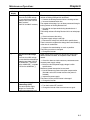
8-2-2 Motor Fails to Operate . . . . . . . . . . . . . . . . . . . . . . . . . . . . . . . . . . . . . . . . . . . . . . . . .
8-2-3 Motor Rotates in the Wrong Direction . . . . . . . . . . . . . . . . . . . . . . . . . . . . . . . . . . . . .
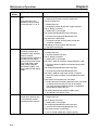
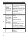
8-2-4 Motor Outputs No Torque or Acceleration is Slow . . . . . . . . . . . . . . . . . . . . . . . . . . .
8-2-5 Speed Accuracy of the Inverter Rotating at High Speed in Vector Control is Low . .
8-2-6 Motor Deceleration Rate is Low . . . . . . . . . . . . . . . . . . . . . . . . . . . . . . . . . . . . . . . . .
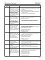
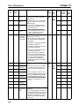
8-2-7 Vertical-axis Load Drops when Brakes are Applied . . . . . . . . . . . . . . . . . . . . . . . . . .
8-2-8 Motor Burns . . . . . . . . . . . . . . . . . . . . . . . . . . . . . . . . . . . . . . . . . . . . . . . . . . . . . . . . .
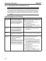
8-2-9 Controller or AM Radio Receives Noise when Inverter is Started . . . . . . . . . . . . . . .
8-2-10 Ground Fault Interrupter is Actuated when Inverter is Started . . . . . . . . . . . . . . . . . .
8-2-11 Mechanical Vibration . . . . . . . . . . . . . . . . . . . . . . . . . . . . . . . . . . . . . . . . . . . . . . . . . .
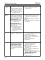
8-2-12 Stable PID Control is Not Possible or Control Fails . . . . . . . . . . . . . . . . . . . . . . . . . .
8-2-13 Inverter Vibration in Energy-saving Control . . . . . . . . . . . . . . . . . . . . . . . . . . . . . . . .
8-2-14 Motor Rotates after Output of Inverter is Turned OFF . . . . . . . . . . . . . . . . . . . . . . . .
8-2-15 Detects OV (Over voltage) and Stalls when Motor Starts . . . . . . . . . . . . . . . . . . . . . .
8-2-16 Output Frequency Does Not Reach Frequency Reference . . . . . . . . . . . . . . . . . . . . . .
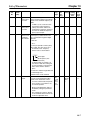
8-2-17 Inverter Does Not Run Because EF
(Simultaneous Inputs of Forward and Reverse Commands) is Detected,
Or Motor Rotates Momentarily When Control Device Power is Turned OFF . . . . . .
8-3 Maintenance and Inspection . . . . . . . . . . . . . . . . . . . . . . . . . . . . . . . . . . . . . . . . . . . . . . . . . . .
8-2
8-2
8-10
8-14
8-14
8-14
8-16
8-16
8-17
8-17
8-17
8-18
8-18
8-18
8-19
8-19
8-20
8-20
8-20
8-21
8-21
8-22
Table of Contents
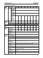
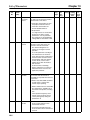
Chapter 9. Specifications . . . . . . . . . . . . . . . . . . . . . . . . . . . . . . . . . . . . 9-1
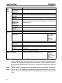
9-1 Inverter Specifications . . . . . . . . . . . . . . . . . . . . . . . . . . . . . . . . . . . . . . . . . . . . . . . . . . . . . . . .
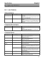
9-2 Option Specifications . . . . . . . . . . . . . . . . . . . . . . . . . . . . . . . . . . . . . . . . . . . . . . . . . . . . . . . .
9-2-1 List of Options . . . . . . . . . . . . . . . . . . . . . . . . . . . . . . . . . . . . . . . . . . . . . . . . . . . . . . .
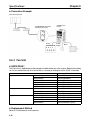
9-2-2 DeviceNet Communications Unit . . . . . . . . . . . . . . . . . . . . . . . . . . . . . . . . . . . . . . . . .
9-2-3 Fan Unit . . . . . . . . . . . . . . . . . . . . . . . . . . . . . . . . . . . . . . . . . . . . . . . . . . . . . . . . . . . .
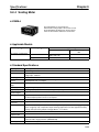
9-2-4 Scaling Meter . . . . . . . . . . . . . . . . . . . . . . . . . . . . . . . . . . . . . . . . . . . . . . . . . . . . . . . .
9-2-5 Braking Resistor . . . . . . . . . . . . . . . . . . . . . . . . . . . . . . . . . . . . . . . . . . . . . . . . . . . . . .
9-2-6 Braking Resistor Unit . . . . . . . . . . . . . . . . . . . . . . . . . . . . . . . . . . . . . . . . . . . . . . . . . .
9-2-7 DC Reactor . . . . . . . . . . . . . . . . . . . . . . . . . . . . . . . . . . . . . . . . . . . . . . . . . . . . . . . . . .
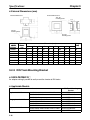
9-2-8 DIN Track Mounting Bracket . . . . . . . . . . . . . . . . . . . . . . . . . . . . . . . . . . . . . . . . . . . .
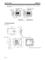
9-2-9 Digital Operators . . . . . . . . . . . . . . . . . . . . . . . . . . . . . . . . . . . . . . . . . . . . . . . . . . . . . .
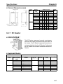
9-2-10 AC Reactor . . . . . . . . . . . . . . . . . . . . . . . . . . . . . . . . . . . . . . . . . . . . . . . . . . . . . . . . . .
9-2-11 EMC-compatible Noise Filter . . . . . . . . . . . . . . . . . . . . . . . . . . . . . . . . . . . . . . . . . . .
9-2-12 Simple Input Noise Filter and Input Noise Filter . . . . . . . . . . . . . . . . . . . . . . . . . . . . .
9-2-13 Output Noise Filter . . . . . . . . . . . . . . . . . . . . . . . . . . . . . . . . . . . . . . . . . . . . . . . . . . . .
9-2
9-7
9-7
9-9
9-10
9-11
9-12
9-14
9-15
9-16
9-17
9-20
9-22
9-30
9-32
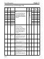
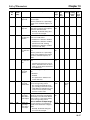
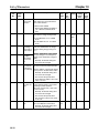
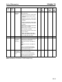
Chapter 10. List of Parameters . . . . . . . . . . . . . . . . . . . . . . . . . . . . . . 10-1
Chapter 11. Using the Inverter for a Motor . . . . . . . . . . . . . . . . . . . . . 11-1
Revision History . . . . . . . . . . . . . . . . . . . . . . . . . . . . . . . . .
R-1
1
Chapter 1
Overview
1-1
1-2
1-3
Functions
Nomenclature
New Features
Chapter 1
Overview
1-1
Functions
The multi-function compact SYSDRIVE 3G3MV-Series Inverter is the first compact
Inverter to feature open-loop vector control.
The 3G3MV Inverter meets EC Directives and UL/cUL standard requirements for worldwide use.
Furthermore, the 3G3MV-Series Inverter incorporates a variety of convenient control,
network, and I/O functions that are versatile and easy-to-use.
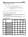
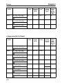
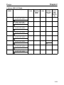
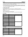
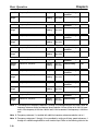
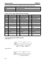
H SYSDRIVE 3G3MV Inverter Models
• The following 200-V-class (three- and single-phase 200-V AC types) and 400-V-class (three-phase
400-V AC type) 3G3MV models are available.
Rated voltage
3-phase
p
200 V AC
Single-phase
g p
200 V AC
3-phase
p
400 V AC
Enclosure rating
Panel-mounting
g models
(
(conform
f
to IP20)
IP )
Closed wall-mounting
models (conform to
NEMA1 and IP20)
Panel-mounting
g models
(
(conform
f
to IP20)
IP )
Panel-mounting
g models
(
(conform
f
to IP20)
Closed wall-mounting
models (conform to
NEMA1 and IP20)
Maximum applied
motor capacity
0.1 (0.1) kW
0.25 (0.2) kW
0.55 (0.4) kW
1.1 (0.75) kW
1.5 (1.5) kW
2.2 (2.2) kW
3.7 (3.7) kW
5.5 (5.5) kW
Model
3G3MV-A2001
3G3MV-A2002
3G3MV-A2004
3G3MV-A2007
3G3MV-A2015
3G3MV-A2022
3G3MV-A2037
3G3MV-A2055
7.5 (7.5) kW
3G3MV-A2075
0.1 (0.1) kW
0.25 (0.2) kW
0.55 (0.4) kW
1.1 (0.75) kW
1.5 (1.5) kW
2.2 (2.2) kW
3.7 (3.7) kW
0.37 (0.2) kW
0.55 (0.4) kW
1.1 (0.75) kW
1.5 (1.5) kW
2.2 (2.2) kW
3.7 (3.7) kW
5.5 (5.5) kW
3G3MV-AB001
3G3MV-AB002
3G3MV-AB004
3G3MV-AB007
3G3MV-AB015
3G3MV-AB022
3G3MV-AB037
3G3MV-A4002
3G3MV-A4004
3G3MV-A4007
3G3MV-A4015
3G3MV-A4022
3G3MV-A4037
3G3MV-A4055
7.5 (7.5) kW
3G3MV-A4075
Note The figures in parentheses indicate capacities for motors used in Japan.
1-2
Chapter 1
Overview
H Powerful Torque Ideal for a Variety of Applications
The 3G3MV is OMRON’s first compact Inverter incorporating an open-loop vector control function,
which ensures a torque output that is 150% of the rated motor torque at an output frequency of 1 Hz.
Ensures a more powerful revolution at low frequencies than any conventional inverter. Furthermore, the
3G3MV Inverter suppresses the revolution fluctuation caused by the load.
Incorporates a fully automatic torque boost function that drives the motor powerfully in V/f control.
Incorporates a high-speed current limit function, thus suppressing overcurrent caused by high torque
and ensuring smooth operation of the motor.
H Convenient Easy-to-use Functions
• The FREQUENCY adjuster of the Digital Operator allows easy operation. The default setting is for
operation according to the FREQUENCY adjuster setting.
• The Digital Operator has a parameter copy function ensuring easy parameter control.
• Ease of maintenance is ensured. The cooling fan is easily replaceable. The life of the cooling fan can
be prolonged by turning ON the cooling fan only when the Inverter is in operation.
• Incorporates a control transistor. Therefore, the Inverter will provide powerful control by just connecting a braking resistor.
• Incorporates an inrush current preventive circuit that prevents contact weld at the input power supply
block.
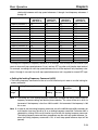
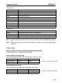
H International Standards (EC Directives and UL/cUL Standards)
The 3G3MV Inverter meets the EC Directives and UL/cUL standard requirements for worldwide use.
EC Directives
UL/cUL
Classification
EMC directive
Low-voltage directive
Applicable standard
EN61800-3
EN50178
UL508C
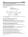
H Compatible with DeviceNet and RS-422/485
• Supports RS-422 and RS-485 communications conforming to the MODBUS Communications Protocol, thus making it possible to easily construct networks with the use of the Protocol Macro or ASCII
Unit mounted on an OMRON SYSMAC PLC. The MODBUS Communications Protocol is a trademark
of AEG Schneider Automation.
• Connects to the 3G3MV-PDRT2 DeviceNet Communications Unit. A remote I/O function for DeviceNet communications Unit is available to the 3G3MV Inverter, which ensures ease of communications
just like standard I/O communications.
Furthermore, DeviceNet communications conform to the DeviceNet communications protocol for
open networks, thus allowing construction of multi-vendor networks in which other companies’
devices can coexist.
Note 1. MODBUS communications and DeviceNet communications cannot be performed simultaneously. It is necessary to select the type of communications required.
Note 2. Only DeviceNet Communications Units manufactured after January 1st, 2000 can be connected to 5.5-kW and 7.5-kW Inverters. Earlier products are not compatible with these Inverters.
1-3
Chapter 1
Overview
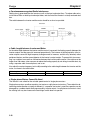
H Handles a Variety of I/O Signals
Handles a variety of I/O signals over a wide application range as described below.
• Analog voltage input: 0 to 10 V
• Analog current input: 4 to 20 or 0 to 20 mA
• Pulse train input:
0.1 to 33.0 kHz set with parameter
• Multi-function analog output or pulse train output is selectable as monitor output
H Suppression of Harmonics
Connects to DC reactors, thus suppressing harmonics more effectively than conventional AC reactors.
Further improvement in the suppression of harmonics is possible with the combined use of the DC and
AC reactors.
1-4
Overview
1-2
Chapter 1
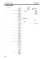
Nomenclature
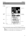
H Panel
Digital Operator
Front panel
mounting
screw
RUN indicator
ALARM display
Terminal
cover
Front cover
Four
mounting
holes
Bottom cover
Note None of the following 200-V models have a terminal cover or mounting holes. Instead, the front
cover is used as a terminal cover and two U-shaped cutouts are provided in place of the mounting
holes.
3G3MV-A2001 (0.1 kW), 3G3MV-A2002 (0.2 kW), 3G3MV-A2004 (0.4 kW), and 3G3MV-A2007
(0.75 kW)
3G3MV-AB001 (0.1 kW), 3G3MV-AB002 (0.2 kW), and 3G3MV-AB004 (0.4 kW)
1-5
Chapter 1
Overview
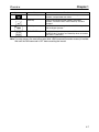
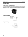
H Digital Operator
Data display
Simplified-LED
indicators
FREQUENCY
adjuster
Operation keys
Appearance
Name
Data display
Function
Displays relevant data items, such as frequency reference,
output frequency, and parameter set values.
FREQUENCY adjuster
Sets the frequency reference within a range between 0 Hz
and the maximum frequency.
FREF indicator
The frequency reference can be monitored or set while this
indicator is lit.
The output frequency of the Inverter can be monitored
while this indicator is lit.
The output current of the Inverter can be monitored while
this indicator is lit.
The values set in U01 through U18 are monitored while
this indicator is lit.
The direction of rotation can be selected while this
indicator is lit when operating the Inverter with the RUN
Key.
The operation of the Inverter through the Digital Operator
or according to the set parameters is selectable while this
indicator is lit.
FOUT indicator
IOUT indicator
MNTR indicator
F/R indicator
LO/RE indicator
PRGM indicator
Mode Key
Increment Key
1-6
Note This status of this indicator can be only monitored
while the Inverter is in operation. Any RUN command
input is ignored while this indicator is lit.
The parameters in n001 through n179 can be set or
monitored while this indicator is lit.
Note While the Inverter is in operation, the parameters can
be only monitored and only some parameters can be
changed. Any RUN command input is ignored while
this indicator is lit.
Switches the simplified-LED (setting and monitor) item
indicators in sequence.
Parameter being set will be canceled if this key is pressed
before entering the setting.
Increases multi-function monitor numbers, parameter
numbers, and parameter set values.
Chapter 1
Overview
Appearance
Name
Decrement Key
Function
Decreases multi-function monitor numbers, parameter
numbers, and parameter set values.
Enter Key
Enters multi-function monitor numbers, parameter
numbers, and internal data values after they are set or
changed.
RUN Key
Starts the Inverter running when the 3G3MV is in operation
with the Digital Operator.
STOP/RESET Key
Stops the Inverter unless parameter n007 is set to disable
the STOP Key. Functions as a Reset Key when an Inverter
error occurs. (See note.)
Note For safety reasons, the reset will not work while a RUN command (forward or reverse) is in effect.
Wait until the RUN command is OFF before resetting the Inverter.
1-7
Overview
1-3
Chapter 1
New Features
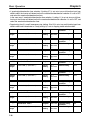
New features have been added to 3G3MV-Series models with 5.5-kW and 7.5-kW capacities (i.e., the 3G3MV-A2055/A2075/ A4055/A4075). These features are outlined
below and explained in detail in Chapter 6.
H New Features for 3G3MV-A2055/A2075/A4055/A4075 Only
D Enclosure Rating: Closed Wall-mounting Conforming to IP20/NEMA1
The 5.5-kW and 7.5-kW Inverters have closed wall-mounting specifications that conform to
IP20/NEMA1, so they can operate in an ambient temperature range of –10 to 40°C.
Note To operate this Inverter within an ambient temperature range of –10 to 50°C, remove the top and
bottom covers to convert it to a panel-mounting model (IP00).
D Default Settings Changed for V/f Patterns (Parameters: n011 to n017)
For 5.5-kW and 7.5-kW Inverters, two of the default settings have been changed. The default settings
for the middle output frequency voltage (VC) (n015) and the minimum output frequency voltage (VMIN
(n017) have both been changed to 10 V for 200-V-class models and to 20 V for 400-V-class models.
D Inverter Overheating Warning Input
(Parameters: n050 to n056; Fault Display: oH3)
An Inverter overheating warning input has been added as a new function that can be set for multi-function inputs 1 to 7 (n050 to n056). When this warning is input, an oH3 fault (nonfatal error) will be displayed. This input can be used for functions such as thermal contact connections for peripheral overheating detection.
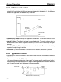
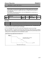
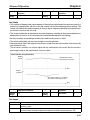
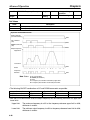
D Frequency Reference Loss Detection (Parameter: n064)
When the frequency is referenced using analog frequency reference inputs (0 to 10 V/4 to 20 mA/0 to 20
mA), this function detects sudden changes in analog inputs as errors (disconnection, short circuit,
breakdown, etc.) and outputs the frequency reference loss output that is set in multi-function outputs 1
to 3 (n057 to n059). After the change is detected, operation continues at 80% of the frequency reference
prior to the change.
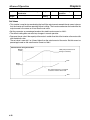
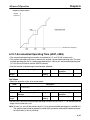
D Accumulated Operating Time (Monitor: U-13; Parameters: n087, n088)
This function calculates and stores in memory the Inverter’s accumulated power-ON time or RUN time.
Use it for checking and determining the maintenance schedule.
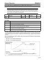
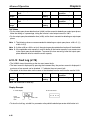
D Speed Search Adjustment (Parameters: n101, n102)
A function has been added for adjusting the speed search. (The speed search is a function for detecting
and smoothly controlling the speed of a free running motor.) The speed search operating time and
search level can be adjusted.
D Input Open-phase Detection
(Parameters: n166, n167; Fault Display: PF)
This function detects the Inverter’s input power supply open phase. Open phases are detected through
main circuit voltage fluctuations, so this function can also be used for detecting abnormal voltage fluctuations in the input power supply voltage.
1-8
Overview
Chapter 1
D Output Open-phase Detection
(Parameters: n168, n169; Fault Display: LF)
This function detects open phases between the Inverter output and the motor.
D Ground Fault Detection (Fault Display: GF)
This function detects ground faults between the Inverter output and the motor.
D Load Short-circuit Detection (Fault Display: SC)
Prior to an Inverter output, this function detects whether the output is short-circuited. If short-circuiting
occurs during an output, it detects an overcurrent (oC).
H New Features for All 3G3MV Models
D Communications Error Monitor (Monitor: U-15)
This function displays communications errors that occur during serial communications
(RS-422/RS-485). The errors that are displayed have the same content as the general serial communications error at register number 003D Hex.
D Pulse Train Frequency Reference Input Filter Constant
(Parameter: n076)
This function sets the primary lag digital filter for pulse train frequency reference inputs.
D Multi-function Analog Inputs (Parameters: n077 to n079)
A function has been added to enable setting the Digital Operator’s multi-function analog voltage (current) inputs. It can set auxiliary analog inputs such as auxiliary frequency references and frequency
reference bias or gain.
Note If multi-function analog inputs are set for use with PID control, no other multi-function analog input
functions can be set or they will overlap.
H New Features for 3G3MV Series (Software Version 0028 (3.7 kW or
Less) or Higher)
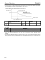
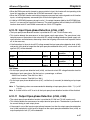
D Operation Continuation Timer Added to the Momentary Power Interruption
Compensation Parameter (n081)
Parameter n081 can be set so that operation will not restart after a power interruption until the RUN
signal is ON for the time specified for the parameter (5 to 100 x 0.1 s). If the parameter is set to 2 (Inverter
restarts when power is restored), operation will recover for all Inverters at the same time, meaning the
power supply capacity must be sufficient for the maximum current. By setting timers to between 0.5 and
10.0 s, differences can be created in the Inverter recovery time to prevent tripping the power supply
breaker, which could happen if all Inverters recovered at the same time.
D Enter Command (Saving Parameters to EEPROM) Operation Selection (n170) To
Enable the Enter Command at Any Time
Previously, operation had to be stopped to use the Enter command to saved changes made to parameters during operation using DeviceNet or RS-422/485 communications. This sometimes caused saving
parameters to be forgotten when a system could not be stopped immediately after changing parameters, causing the need to reset the parameters again when they were lost at the next power interruption
or system shutdown. The new parameter n170 can be set to 1 to enable using the Enter command to
write parameters to EEPROM even during operation.
1-9
2
Chapter 2
Design
2-1
2-2
Installation
Wiring
Chapter 2
Design
2-1
Installation
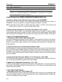
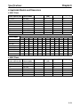
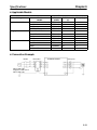
2-1-1 Dimensions
D 3G3MV-A2001 to 3G3MV-A2007 (0.1 to 0.75 kW) 3-phase 200-V AC Input
3G3MV-AB001 to 3G3MV-AB004 (0.1 to 0.4 kW) Single-phase 200-V AC Input
Rated voltage
g
Dimensions (mm)
Model 3G3MV-
D
3-phase
p
200 V AC
Single-phase
200 V AC
g p
2-2
A2001
A2002
A2004
A2007
AB001
AB002
AB004
76
76
108
128
76
76
131
Weight
g ((kg)
g)
t
3
3
5
5
3
3
5
Approx. 0.6
Approx. 0.6
Approx. 0.9
Approx. 1.1
Approx. 0.6
Approx. 0.7
Approx. 1.0
Chapter 2
Design
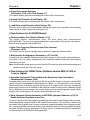
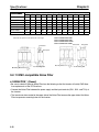
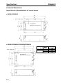
D 3G3MV-A2015 to 3G3MV-A2022 (1.5 to 2.2 kW) 3-phase 200-V AC Input
3G3MV-AB007 to 3G3MV-AB015 (0.75 to 1.5 kW) Single-phase 200-V AC Input
3G3MV-A4002 to 3G3MV-A4022 (0.2 to 2.2 kW) 3-phase 400-V AC Input
Four, 5 dia.
Rated voltage
g
Model 3G3MV-
Dimensions (mm)
Weight
g ((kg)
g)
D
3-phase
p
200 V AC
Single-phase
200 V AC
g p
3-phase
p
400 V AC
A2015
A2022
AB007
AB015
A4002
A4004
A4007
A4015
A4022
131
140
140
156
92
110
140
156
156
Approx. 1.4
Approx. 1.5
Approx. 1.5
Approx. 1.5
Approx. 1.0
Approx. 1.1
Approx. 1.5
Approx. 1.5
Approx. 1.5
2-3
Chapter 2
Design
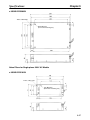
D 3G3MV-A2037 (3.7 kW) 3-phase 200-V AC Input
3G3MV-AB022 (2.2 kW) Single-phase 200-V AC Input
3G3MV-A4037 (3.7 kW) 3-phase 400-V AC Input
Four, 5 dia.
Rated voltage
g
Model 3G3MV-
Dimensions (mm)
Weight
g ((kg)
g)
D
3-phase 200 V AC
Single-phase 200 V AC
3-phase 400 V AC
A2037
AB022
A4037
143
163
143
Approx. 2.1
Approx. 2.2
Approx. 2.1
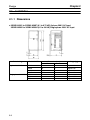
D 3G3MV-AB037 (3.7 kW) Single-phase 200-V AC Input
Four, 5 dia.
Rated voltage
g
Model 3G3MV-
Dimensions (mm)
Weight
g ((kg)
g)
D
Single-phase 200 V AC
2-4
AB037
180
Approx. 2.9
Chapter 2
Design
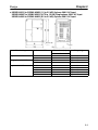
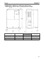
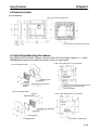
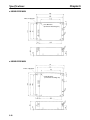
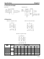
D 3G3MV-A2055 to -A2075 (5.5 to 7.5 kW) 3-phase 200-V AC Input
3G3MV-A4055 to -A4075 (5.5 kW to 7.5 kW) 3-phase 400-V AC Input
Two, 6 dia.
Rated voltage
g
Model 3G3MV-
Dimensions (mm)
Weight
g ((kg)
g)
D
3-phase 200 V AC
3-phase 200 V AC
3-phase 400 V AC
3-phase 400 V AC
A2055
A2075
A4055
A4075
170
170
170
170
Approx. 4.6
Approx. 4.8
Approx. 4.8
Approx. 4.8
2-5
Chapter 2
Design
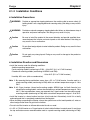
2-1-2 Installation Conditions
H Installation Precautions
!
WARNING
Provide an appropriate stopping device on the machine side to secure safety. (A
holding brake is not a stopping device for securing safety.) Not doing so may result in
injury.
!
WARNING
Provide an external emergency stopping device that allows an instantaneous stop of
operation and power interruption. Not doing so may result in injury.
! Caution
Be sure to install the product in the correct direction and provide specified clearances between the Inverter and control panel or with other devices. Not doing so
may result in fire or malfunction.
! Caution
Do not allow foreign objects to enter inside the product. Doing so may result in fire or
malfunction.
! Caution
Do not apply any strong impact. Doing so may result in damage to the product or
malfunction.
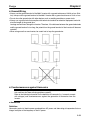
H Installation Direction and Dimensions
• Install the Inverter under the following conditions.
Ambient operating temperature:
Panel-mounting models (conforming to IP20): –10 to 50°C (0.1- to 3.7-kW Inverters)
Closed wall-mounting models (conforming to NEMA1 and IP20):
–10 to 40°C (5.5- to 7.5-kW Inverters)
Humidity: 95% max. (with no condensation)
Note 1. By removing the top and bottom covers from a 5.5- to 7.5-kW Inverter, it can be used as a
panel-mounting model (conforming to IP00) within an ambient temperature range of –10 to
50°C.
Note 2. All C-type Inverters (closed wall-mounting models: NEMA1-type for North America) are
closed wall-mounting models, and can be used within an ambient temperature range of –10 to
40°C. If the top and bottom covers are removed, the C-type Inverters can be used as panelmounting models (conforming to IP00) within an ambient temperature range of –10 to 50°C.
• Install the Inverter in a clean location free from oil mist and dust. Alternatively, install it in a totally
enclosed panel that is completely protected from floating dust.
• When installing or operating the Inverter, always take special care so that metal powder, oil, water, or
other foreign matter does not get into the Inverter.
• Do not install the Inverter on inflammable material such as wood.
• If a 5.5- to 7.5-kW Inverter or a C-type Inverter is to be installed inside of a control panel, it must have
the top and bottom covers removed and be used as a panel-mounting model (conforming to IP00).
2-6
Chapter 2
Design
H Direction
• Install the Inverter on a vertical surface so that the characters on the nameplate are oriented upward.
H Dimensions
• When installing the Inverter, always provide the following clearances to allow normal heat dissipation
from the Inverter.
W = 30 mm min. (0.1 to 4.0 kW)
50 mm min. (5.5 to 7.5 kW)
Inverter
Inverter
100 mm min.
Inverter
Air
Side
100 mm min.
Air
H Ambient Temperature Control
• To enhance operation reliability, the Inverter should be installed in an environment free from extreme
temperature changes.
• If the Inverter is installed in an enclosed environment such as a box, use a cooling fan or air conditioner
to maintain the internal air temperature below 50°C.
The life of the built-in electrolytic capacitors of the Inverter is prolonged by maintaining the internal air
temperature as low as possible.
• The surface temperature of the Inverter may rise approximately 30°C higher than the ambient temperature. Be sure to keep away equipment and wires from the Inverter as far as possible if the equipment
and wires are easily influenced by heat.
H Protecting Inverter from Foreign Matter during Installation
• Place a cover over the Inverter during installation to shield it from metal power produced by drilling.
Upon completion of installation, always remove the cover from the Inverter. Otherwise, ventilation will
be affected, causing the Inverter to overheat.
2-7
Chapter 2
Design
2-1-3 Removing and Mounting the Covers
To mount the Inverter, it is necessary to remove the front cover, terminal cover (unless
the Inverter is a 200-V model), and the Digital Operator. To wire the Inverter, it is necessary to remove the front cover, terminal cover (unless the Inverter is a 200-V model), and
bottom cover from the Inverter.
Follow the instructions below to remove the covers from the Inverter.
To mount the covers, take the opposite steps.
H Removing the Front Cover
• Loosen the front cover mounting screws with a screwdriver.
• Press the left and right sides of the front cover in the arrow 1 directions and lift the bottom of the cover in
the arrow 2 direction to remove the front cover as shown in the following illustration.
H Removing the Digital Operator
• After removing the front cover, lift up the upper and lower right-hand sides (positions A) of the Digital
Operator in the direction of arrow 1 as shown in the following illustration.
A
A
2-8
Design
Chapter 2
H Removing the Terminal Cover
D 0.2- to 3.7-kW Inverters
• After the front cover is removed, press the left and right sides of the terminal cover in the arrow 1 directions and lift the terminal cover in the arrow 2 direction as shown in the following illustration.
D 5.5-/7.5-kW Inverters
• Loosen the terminal cover screws in the direction of arrows 1.
• Press the left and right sides of the terminal cover in the direction of arrows 2 and lift it in the direction of
arrow 3 as shown in the following illustration.
Note None of the following 200-V models have a terminal cover. Instead, the front cover is used as a
terminal cover.
3G3MV-A2001 (0.1 kW), 3G3MV-A2002 (0.2 kW), 3G3MV-A2004 (0.4 kW), 3G3MV-A2007 (0.75
kW), 3G3MV-AB001 (0.1 kW), 3G3MV-AB002 (0.2 kW), and 3G3MV-AB004 (0.4 kW)
2-9
Chapter 2
Design
H Removing the Bottom Cover
D 0.2- to 3.7-kW Inverters
• After removing the front cover and terminal cover, press the bottom cover in the arrow 1 direction
based on position A as a fulcrum.
A
A
D 5.5-/7.5-kW Inverters
• After removing the terminal cover, loosen the fastening screws.
2-10
Chapter 2
Design
2-2
Wiring
!
WARNING
Wiring must be performed only after confirming that the power supply has been
turned OFF. Not doing so may result in electrical shock.
!
WARNING
Wiring must be performed by authorized personnel. Not doing so may result in
electrical shock or fire.
!
WARNING
Be sure to confirm operation only after wiring the emergency stop circuit. Not doing
so may result in injury.
!
WARNING
Always connect the ground terminals to a ground of 100 Ω or less for the 200-V AC
class, or 10 Ω or less for the 400-V AC class. Not connecting to a proper ground may
result in electrical shock.
! Caution
Install external breakers and take other safety measures against short-circuiting in
external wiring. Not doing so may result in fire.
! Caution
Confirm that the rated input voltage of the Inverter is the same as the AC power supply voltage. An incorrect power supply may result in fire, injury, or malfunction.
! Caution
Connect the Braking Resistor and Braking Resistor Unit as specified in the manual.
Not doing so may result in fire.
! Caution
Be sure to wire correctly and securely. Not doing so may result in injury or damage to
the product.
! Caution
Be sure to firmly tighten the screws on the terminal block. Not doing so may result in
fire, injury, or damage to the product.
! Caution
Do not connect an AC power to the U, V, or W output. Doing so may result in damage
to the product or malfunction.
! Caution
The motor may start operation if input terminal S2 is turned ON with the default
parameter settings. Wire terminals with NC contacts (e.g., 3-wire sequences) only
after setting the multi-function input parameters.
2-11
Chapter 2
Design
2-2-1 Terminal Block
To wire the terminal block of the Inverter, remove the front cover, terminal cover (unless
the Inverter is a low-capacity 200-V model), and bottom cover from the Inverter.
There is a label under the front cover indicating the arrangement of main circuit terminals. Be sure to remove the label after wiring the terminals. The output terminal of the
motor has a label as well. Remove the label before wiring the motor terminal.
H Arrangement of Control Circuit Terminals
Control circuit terminals
H Arrangement of Main Circuit Terminals
D 3G3MV-A2001 through 3G3MV-A2007 (0.1 through 0.75 kW):
3-phase 200-V AC Input
3G3MV-AB001 through 3G3MV-AB004 (0.1 through 0.4 kW):
Single-phase 200-V AC Input
Power supply input
Motor output
Braking Resistor
Note For single-phase input, connect R/L1 and S/L2.
2-12
Chapter 2
Design
D 3G3MV-A2015 to 3G3MV-A2022 (1.5 to 2.2 kW): 3-phase 200-V AC Input
3G3MV-AB007 to 3G3MV-AB015 (0.75 to 1.5 kW):
Single-phase 200-V AC Input
3G3MV-A4002 to 3G3MV-A4022 (0.2 to 2.2 kW): 3-phase 400-V AC Input
Power supply input
Braking
Resistor
Motor output
Note For single-phase input, connect R/L1 and S/L2.
D 3G3MV-A2037 to -A2075 (3.7 to 7.5 kW): 3-phase 200-V AC Input
3G3MV-AB022 to 3G3MV-AB037 (2.2 to 3.7 kW):
Single-phase 200-V AC Input
3G3MV-A4037 to -A4075 (3.7 to 7.5 kW): 3-phase 400-V AC Input
Power supply input
Braking
Resistor
Motor output
Note For single-phase input, connect R/L1 and S/L2.
2-13
Chapter 2
Design
H Main Circuit Terminals
Symbol
R/L1
S/L2
Name
Power supply
pp y input
p
t
terminals
i l
T/L3
U/T1
Motor output terminals
Description
3G3MV-A2j: 3-phase
p
200 to 230 V AC
3G3MV-ABj: Single-phase
g p
200 to 240 V AC (See
(
note 1.))
3G3MV-A4j: 3-phase 380 to 460 V AC
3-phase power supply output for driving motors. (See note 2.)
3G3MV A2j 3
h
200 tto 230 V AC
3G3MV-A2j:
3-phase
V/T2
3G3MV-ABj: 3-phase 200 to 240 V AC
W/T3
B1
B2
+1
+2
–
Braking
g Resistor
i terminals
i l
connection
Connection terminals +1
and +2:
DC reactor connection
terminals
+1 and –:
DC power supply input
terminals
Ground terminal
3G3MV-A4j: 3-phase 380 to 460 V AC
Terminals for attaching
g an external Braking
g Resistor or a Braking
g
R i
U i (Connect
(C
d
l
d i braking.)
b ki )
Resistor
Unit.
to detect
overvoltage
during
Connect the DC reactor for suppressing harmonics to terminals +1
and +2.
When driving the Inverter with DC power, input the DC power to
terminals +1 and –.
(Terminal +1 is a positive terminal.)
terminal )
Be sure to ground the terminal under the following conditions.
3G3MV-A2j: Ground at a resistance of 100 Ω or less.
3G3MV-ABj: Ground at a resistance of 100 Ω or less.
3G3MV-A4j: Ground at a resistance of 10 Ω or less. To conform
to EC Directives, connect to the neutral point of the power supply.
Note
Be sure to connect the ground terminal directly to the
motor frame ground.
Note 1. Connect single-phase input to both the R/L1 terminal and the S/L2 terminal.
Note 2. The maximum voltage at the output side corresponds to the power supply voltage for Inverter
input.
2-14
Chapter 2
Design
H Control Circuit Terminals
Symbol
Input S1
S2
S3
S4
S5
S6
S7
SC
FS
FR
FC
RP
CN2
1
2
3
Name
Multi-function input 1 (Forward/Stop)
Multi-function input 2
(Reverse/Stop)
Multi-function input 3
(External fault: Normally
open)
Multi-function input 4 (Fault
reset)
Multi-function input 5 (Multi-step speed reference 1)
Multi-function input 6 (Multi-step speed reference 2)
Multi-function input 7 (Inching frequency command)
Sequence input common
Frequency reference
power supply output
Frequency reference input
Frequency reference common
Pulse train input
Multi-function analog voltage input
Multi-function analog current input
Multi-function analog input
common
Specification
Photocoupler
8 mA at 24 V DC
C (See
(S notes 2 and 3.)
3)
20 mA at 12 V DC
0 to 10 V DC (Input
20 kΩ))
( p impedance:
p
Response frequency: 0 to 33 kHz (30% to 70% ED)
H: 3.5 to 13.2 V
L: 0.8 V max.
(Input impedance: 2.24 kΩ)
Voltage input (between terminals 1 and 3): 0 to 10 V DC
20
((Input
p impedance:
p
0 kΩ))
Current input (between terminals 2 and 3): 4 to 20 mA
(Input impedance: 250 Ω)
2-15
Chapter 2
Design
Symbol
OutMA
put
p
MB
MC
P1
Name
Multi-function contact output (Normally open: Fault)
Multi-function contact output (Normally closed:
Fault)
Multi-function contact output common
Multi-function photocoupler
output 1 (During operation)
Specification
Relay output
1 A max. at 30 V DC
C
1 A max. at 250 V AC
Open collector output 50 mA max.
at 48 V DC
P2
Multi-function photocoupler
output 2 (Frequency
matching)
PC
Multi-function photocoupler
output common
Multi-function analog out• Analog output: 2 mA max. at 0 to 10 V DC
put
AM
• Pulse train output (max. output voltage: 12 V DC)
(See note 4.)
When Used as Voltage Output
AC
Multi-function analog output common
Output voltage (insulation type)
Load impedance
+5 V
1.5 kΩ min.
+10 V
10 kΩ min.
When External Power Supply is Used
External power supply (V)
12 V DC (±5%)
Input current (mA)
from external power
supply
16 mA max.
Load
impedance
External
power
supply
12 V DC
Load
impedance
Input
current
16 mA
max.
External power
supply ground
Note Do not use a 5-V DC or 24-V DC external power supply. Doing so can cause internal circuit damage or
malfunctioning.
Communica
nications
R+
R–
S+
S–
Receiver side
Conforming
g to RS-422/485
Sender side
Note 1. Parameter settings can be used to select various functions for multi-function inputs 1 to 7,
multi-function contact outputs, and multi-function photocoupler outputs. The functions in
parentheses are the default settings.
Note 2. NPN is the default setting for these terminals. Wire them by providing a common ground. No
external power supply is required.
Note 3. To provide an external power supply and wire the terminals through a common positive line,
set SW1 to PNP and use a 24 V DC ±10% power supply.
2-16
Chapter 2
Design
Note 4. When multi-function analog outputs are used for pulse train outputs, they can be directly connected to the pulse train inputs at other 3G3MV-series Inverters for simple synchronization or
other applications.
H Selecting Input Method
• Switches SW1 and SW2, both of which are located above the control circuit terminals, are used for
input method selection.
Remove the front cover and optional cover to use these switches.
Selector
Control circuit
terminal block
D Selecting Sequence Input Method
• By using SW1, NPN or PNP input can be selected as shown below.
SW1
(Default setting)
S1 to 7
SW1
S1 to 7
24 V DC
(±10%)
2-17
Chapter 2
Design
D Selecting RS-422/485 Termination Resistance
• Termination resistance can be selected by setting pin 1 of the SW2 to ON. The default setting for the
pin is OFF.
Selects RS-422/485 termination resistance
Selects frequency reference input method
Communications method
Pin 1 setting
RS-422
RS-485
Set to ON
Set to ON only if the Unit is the end Slave.
120-Ω termination resistance (1/2 W)
Pin 1
D Selecting Frequency Reference Input Method
• By using pin 2 of SW2, voltage input or current input can be selected as the input method for frequency
reference. The default setting is for voltage input.
Parameter settings are required together with the selection of the frequency reference input method.
Frequency reference input
method
Voltage input (default setting)
Current input
Pin 2 setting
Frequency reference selection
(parameter n004)
Set value 2
Set value 3 or 4
V (OFF)
I (ON)
Note Do not set pin 2 to ON for current input while voltage is being input, otherwise the resistor in the
input circuit may burn out.
D Frequency Reference Input by Pulse Train Input
• The RP terminal can input or output a PLC or external pulse generator signal directly to the Inverter if
an analog signal is unable to provide an accurate reference.
• This allows speed ratio and tracking operation between inverters.
Pulse train
Input
2-18
Pulse train
Output
Input
Chapter 2
Design
D Frequency Reference Input by PLC Pulse Train
to
to
ON when 3.5 V or higher
OFF when 0.8 V or lower
Note Use twisted pair shielded wire no longer than 5 m for pulse train input lines in order to suppress
noise.
2-19
Chapter 2
Design
2-2-2 Standard Connections
DC reactor
(optional)
Braking Resistor
(optional)
Noise Filter
3-phase 200/400 V AC
Single-phase 200 V AC (See note.)
Multi-function contact output
NO
Multi-function input 1
Multi-function input 2
NC
Multi-function input 3
Common
Multi-function input 4
Multi-function input 5
Multi-function
photocoupler output 1
Multi-function input 6
Multi-function input 7
Sequence input common
Multi-function
photocoupler output 2
Frequency reference power
supply 20 mA at +12 V
External
frequency
adjuster (2 kΩ,
1/4 W min.)
Pulse
generator
Multi-function
photocoupler output
common
Frequency reference input
Frequency reference
common
Multi-function analog
output/Pulse monitor
output
Pulse train input
RS-422
communications
(RS-485 selection)
Multi-function analog output
common
Connector
Multi-function analog voltage input
Digital Operator
Multi-function analog current input
Analog input common
Note Connector on CN2 wiring side:
Contact: SZH-002T-P0.5
Housing: ZHR-3
(Products of J.S.T. MFG. Co., Ltd.)
Note Connect single-phase 200 V AC to terminals R/L1 and S/L2 of the 3G3MV-ABj.
2-20
Chapter 2
Design
D Example of 3-wire Sequence Connections
Stop
switch
(NC)
RUN
switch
(NO)
RUN input (Operates with the RUN switch and Stop switch closed)
Direction switch
Stop input (Stops with the Stop switch opened)
Forward/Reverse rotation command input. (Forward with the
Direction switch opened. Reverse with the Direction switch closed)
Sequence input common
Note Set parameter 052 to forward/reverse rotation command 0 for 3-wire sequence input.
2-2-3 Wiring around the Main Circuit
H Wire Size, Terminal Screw, Screw Tightening Torque, and Molded-case
Circuit Breaker Capacities
• For the main circuit and ground, always use 600-V polyvinyl chloride (PVC) cables.
• If any cable is long and may cause voltage drops, increase the wire size according to the cable length.
D 3-phase 200-V AC Model
Model
3G3MV-
Terminal symbol
Terminal
screw
Screw
tightening
torque
(NSm)
Wire size
(mm2)
Recommended
wire size
(mm2)
A2001
R/L1, S/L2, T/L3, B1, B2, –,
+1, +2, U/T1, V/T2, W/T3
M3.5
0.8 to 1.0
0.75 to 2
2
Moldedcase circuit
breaker
capacity
(A)
5
A2002
R/L1, S/L2, T/L3, B1, B2, –,
+1, +2, U/T1, V/T2, W/T3
M3.5
0.8 to 1.0
0.75 to 2
2
5
A2004
R/L1, S/L2, T/L3, B1, B2, –,
+1, +2, U/T1, V/T2, W/T3
M3.5
0.8 to 1.0
0.75 to 2
2
5
A2007
R/L1, S/L2, T/L3, B1, B2, –,
+1, +2, U/T1, V/T2, W/T3
M3.5
0.8 to 1.0
0.75 to 2
2
10
A2015
R/L1, S/L2, T/L3, B1, B2, –,
+1, +2, U/T1, V/T2, W/T3
M4
1.2 to 1.5
2 to 5.5
2
20
3.5
A2022
R/L1, S/L2, T/L3, B1, B2, –,
+1, +2, U/T1, V/T2, W/T3
M4
1.2 to 1.5
2 to 5.5
3.5
20
2-21
Chapter 2
Design
Model
3G3MV-
Terminal symbol
Terminal
screw
Screw
tightening
torque
(NSm)
Wire size
(mm2)
Recommended
wire size
(mm2)
A2037
R/L1, S/L2, T/L3, B1, B2, –,
+1, +2, U/T1, V/T2, W/T3
M4
1.2 to 1.5
2 to 5.5
5.5
Moldedcase circuit
breaker
capacity
(A)
30
A2055
R/L1, S/L2, T/L3, B1, B2, –,
+1, +2, U/T1, V/T2, W/T3
M5
2.5
5.5 to 8
8
50
A2075
R/L1, S/L2, T/L3, B1, B2, –,
+1, +2, U/T1, V/T2, W/T3
M5
2.5
5.5 to 8
8
60
D Single-phase 200-V AC Model
Model
3G3MV-
Terminal symbol
Terminal
screw
Terminal
torque
(NSm)
Wire size
(mm2)
Recommended
wire size
(mm2)
AB001
R/L1, S/L2, T/L3, B1, B2, –,
+1, +2, U/T1, V/T2, W/T3
M3.5
0.8 to 1.0
0.75 to 2
2
Moldedcase circuit
breaker
capacity
(A)
5
AB002
R/L1, S/L2, T/L3, B1, B2, –,
+1, +2, U/T1, V/T2, W/T3
M3.5
0.8 to 1.0
0.75 to 2
2
5
AB004
R/L1, S/L2, T/L3, B1, B2, –,
+1, +2, U/T1, V/T2, W/T3
M3.5
0.8 to 1.0
0.75 to 2
2
10
AB007
R/L1, S/L2, T/L3, B1, B2, –,
+1, +2, U/T1, V/T2, W/T3
M4
1.2 to 1.5
2 to 5.5
3.5
20
AB015
R/L1, S/L2, B1, B2, –, +1, +2,
U/T1, V/T2, W/T3
M4
1.2 to 1.5
2 to 5.5
5.5
20
3.5
AB022
R/L1, S/L2, B1, B2, –, +1, +2,
U/T1, V/T2, W/T3
M4
1.2 to 1.5
2 to 5.5
5.5
40
AB037
R/L1, S/L2, B1, B2, –, +1, +2,
U/T1, V/T2, W/T3
M5
3.0
5.5 to 8
8
50
M4
1.2 to 1.5
2 to 8
5.5
2-22
Chapter 2
Design
D 3-phase 400-V AC Model
Model
3G3MV-
Terminal symbol
Terminal
screw
Screw
tightening
torque
(NSm)
Wire size
(mm2)
Recommended
wire size
(mm2)
A4002
R/L1, S/L2, T/L3, B1, B2, –,
+1, +2, U/T1, V/T2, W/T3
M4
1.2 to 1.5
2 to 5.5
2
Moldedcase circuit
breaker
capacity
(A)
5
A4004
R/L1, S/L2, T/L3, B1, B2, –,
+1, +2, U/T1, V/T2, W/T3
M4
1.2 to 1.5
2 to 5.5
2
5
A4007
R/L1, S/L2, T/L3, B1, B2, –,
+1, +2, U/T1, V/T2, W/T3
M4
1.2 to 1.5
2 to 5.5
2
5
A4015
R/L1, S/L2, T/L3, B1, B2, –,
+1, +2, U/T1, V/T2, W/T3
M4
1.2 to 1.5
2 to 5.5
2
10
A4022
R/L1, S/L2, T/L3, B1, B2, –,
+1, +2, U/T1, V/T2, W/T3
M4
1.2 to 1.5
2 to 5.5
2
10
A4037
R/L1, S/L2, T/L3, B1, B2, –,
+1, +2, U/T1, V/T2, W/T3
M4
1.2 to 1.5
2 to 5.5
2
20
3.5
A4055
R/L1, S/L2, T/L3, B1, B2, –,
+1, +2, U/T1, V/T2, W/T3
M4
1.8
3.5 to 5.5
5.5
30
A4075
R/L1, S/L2, T/L3, B1, B2, –,
+1, +2, U/T1, V/T2, W/T3
M5
2.5
5.5 to 8
5.5
30
2-23
Chapter 2
Design
H Wiring on the Input Side of the Main Circuit
D Installing a Molded-case Circuit Breaker
Always connect the power input terminals (R/L1, S/L2, and T/L3) and power supply via a molded case
circuit breaker (MCCB) suitable to the Inverter.
• Install one wiring circuit breaker per Inverter.
• Choose an MCCB with the capacity indicated in the previous tables (Wire Size, Terminal Screw, Tightening Torque, and Molded-case Circuit Breaker Capacities).
• For the MCCB’s time characteristics, be sure to consider the Inverter’s overload protection (one minute at 150% of the rated output current).
• If the MCCB is to be used in common among multiple Inverters, or other devices, set up a sequence
such that the power supply will be turned OFF by a fault output, as shown in the following diagram.
Inverter
Power
supply
3-phase/
Single-phase
200 V AC
3-phase 400 V AC
(See note.)
Fault output (NC)
Note Use a 400/200 V transformer for a 400-V model.
D Installing a Ground Fault Interrupter
Inverter outputs use high-speed switching, so high-frequency leakage current is generated.
In general, a leakage current of approximately 100 mA will occur for each Inverter (when the power
cable is 1 m) and approximately 5 mA for each additional meter of power cable.
Therefore, at the power supply input area, use a special-purpose breaker for Inverters, which detects
only the leakage current in the frequency range that is hazardous to humans and excludes high-frequency leakage current.
• For the special-purpose breaker for Inverters, choose a ground fault interrupter with a sensitivity
amperage of at least 10 mA per Inverter.
• When using a general leakage breaker, choose a ground fault interrupter with a sensitivity amperage
of 200 mA or more per Inverter and with an operating time of 0.1 s or more.
2-24
Design
Chapter 2
D Installing a Magnetic Contactor
If the power supply of the main circuit is to be shut off because of the sequence, a magnetic contactor
can be used instead of a molded-case circuit breaker.
When a magnetic contactor is installed on the primary side of the main circuit to stop a load forcibly,
however, the regenerative braking does not work and the load coasts to a stop.
• A load can be started and stopped by opening and closing the magnetic contactor on the primary side.
Frequently opening and closing the magnetic contactor, however, may cause the Inverter to break
down. To maintain the service life of the Inverter’s internal relays and electrolytic capacitors, it is recommended that this operation be performed no more than once every 30 minutes.
• When the Inverter is operated with the Digital Operator, automatic operation cannot be performed
after recovery from a power interruption.
• When using the Braking Resistor Unit, be sure to arrange a sequence in which the thermal relay of the
Unit turns the magnetic contactor OFF.
D Connecting Input Power Supply to the Terminal Block
Input power supply can be connected to any terminal on the terminal block because the phase
sequence of input power supply is irrelevant to the phase sequence (R/L1, S/L2, and T/L3).
D Installing an AC Reactor
If the Inverter is connected to a large-capacity power transformer (660 kW or more) or the phase
advance capacitor is switched, an excessive peak current may flow through the input power circuit,
causing the converter unit to break down.
To prevent this, install an optional AC reactor on the input side of the Inverter.
This also improves the power factor on the power supply side.
D Installing a Surge Absorber
Always use a surge absorber or diode for the inductive loads near the Inverter. These inductive loads
include magnetic contactors, electromagnetic relays, solenoid valves, solenoid, and magnetic brakes.
2-25
Chapter 2
Design
D Installing a Noise Filter on the Power Supply Side
The Inverter’s outputs utilize high-speed switching, so noise may be transmitted from the Inverter to the
power line and adversely affect other devices in the vicinity. It is recommended that a Noise Filter be
installed at the Power Supply to minimize this noise transmission. Conversely, noise can also be reduced from the power line to the Inverter.
Wiring Example 1
Input Noise Filters
Simple Input Noise Filter: 3G3EV-PLNFDj
Input Noise Filter: 3G3IV-PFNj
EMC-conforming Input Noise Filter: 3G3MV-PRSj
Power
supply
3G3MV
Noise
Filter
SYSDRIVE
SYSMAC or
other control
device
Note Use a noise filter designed for Inverters. A general-purpose noise filter will be less effective and
may not reduce noise.
H Wiring on the Output Side of the Main Circuit
D Connecting the Terminal Block to the Load
Connect output terminals U/T1, V/T2, and W/T3 to motor lead wires U/T1, V/T2, and W/T3.
Check that the motor rotates forward with the forward command. Switch over any two of the output terminals to each other and reconnect if the motor rotates in reverse with the forward command.
D Never Connect a Power Supply to Output Terminals
Never connect a power supply to output terminals U/T1, V/T2, or W/T3.
If voltage is applied to the output terminals, the internal circuit of the Inverter will be damaged.
D Never Short or Ground Output Terminals
If the output terminals are touched with bare hands or the output wires come into contact with the
Inverter casing, an electric shock or grounding will occur. This is extremely hazardous.
Also, be careful not to short the output wires.
D Do not Use a Phase Advancing Capacitor or Noise Filter
Never connect a phase advance capacitor or LC/RC Noise Filter to the output circuit.
Doing so will result in damage to the Inverter or cause other parts to burn.
D Do not Use an Electromagnetic Switch of Magnetic Contactor
Do not connect an electromagnetic switch of magnetic contactor to the output circuit.
If a load is connected to the Inverter during running, an inrush current will actuate the overcurrent protective circuit in the Inverter.
2-26
Chapter 2
Design
D Installing a Thermal Relay
The Inverter has an electronic thermal protection function to protect the motor from overheating. If, however, more than one motor is operated with one inverter or a multi-polar motor is used, always install a
thermal relay (THR) between the Inverter and the motor and set n037 to 2 (no thermal protection).
In this case, program the sequence so that the magnetic contactor on the input side of the main circuit is
turned OFF by the contact of the thermal relay.
D Installing a Noise Filter on the Output Side
Connect a Noise Filter to the output side of the Inverter to reduce radio noise and induction noise.
Power
supply
3G3MV
3G3IV-PLF
Noise
Filter
SYSDRIVE
Induction noise
Signal line
Radio noise
AM radio
Controller
Induction Noise:
Electromagnetic induction generates noise on the signal line, causing the controller to malfunction.
Radio Noise:
Electromagnetic waves from the Inverter and cables cause the broadcasting
radio receiver to make noise.
D Countermeasures against Induction Noise
As described previously, a Noise Filter can be used to prevent induction noise from being generated on
the output side. Alternatively, cables can be routed through a grounded metal pipe to prevent induction
noise. Keeping the metal pipe at least 30 cm away from the signal line considerably reduces induction
noise.
Power supply
3G3MV
Metal pipe
SYSDRIVE
30 cm min.
Signal line
Controller
2-27
Chapter 2
Design
D Countermeasures against Radio Interference
Radio noise is generated from the Inverter as well as the input and output lines. To reduce radio noise,
install Noise Filters on both input and output sides, and also install the Inverter in a totally enclosed steel
box.
The cable between the Inverter and the motor should be as short as possible.
Steel box
Metal pipe
3G3MV
Power supply
Noise
Filter
SYSDRIVE
Noise
Filter
D Cable Length between Inverter and Motor
As the cable length between the Inverter and the motor is increased, the floating capacity between the
Inverter outputs and the ground is increased proportionally. The increase in floating capacity at the Inverter outputs causes the high-frequency leakage current to increase, and this may adversely affect
peripheral devices and the current detector in the Inverter’s output section. To prevent this from occurring, use a cable of no more than 100 meters between the Inverter and the motor. If the cable must be
longer than 100 meters, take measures to reduce the floating capacity by not wiring in metallic ducts, by
using a separate cable for each phase, and so on.
Also adjust the carrier frequency (set in n80) according to the cable length between the Inverter and the
motor, as shown in the table below.
Cable length
Carrier frequency
50 m or less
10 kHz max.
100 m or less
5 kHz max.
More than 100 m
2.5 kHz max.
D Single-phase Motors Cannot Be Used
The Inverter is not suited for the variable speed control of single-phase motors.
Single-phase motors are either capacitor start motors or split-phase start motors. (The method for determining rotation direction at startup is different.) If a capacitor start motor is used, the capacitor may be
damaged by a sudden electric discharge caused by Inverter output. If a split-phase start motor is used,
the starting coil may burn because the centrifugal switch does not operate.
2-28
Design
Chapter 2
H Ground Wiring
• Always use the ground terminal of the 200-V Inverter with a ground resistance of 100 Ω or less. Similarly, always use the ground terminal of the 400-V Inverter with a ground resistance of 10 Ω or less.
• Do not share the ground wire with other devices such as welding machines or power tools.
• Always use a ground wire that complies with technical standards on electrical equipment and minimize the length of the ground wire.
Leakage current flows through the Inverter. Therefore, if the distance between the ground electrode
and the ground terminal is too long, the potential on the ground terminal of the Inverter will become
unstable.
• When using more than one Inverter, be careful not to loop the ground wire.
H Countermeasures against Harmonics
With the continuing development of electronics, the generation of harmonics from industrial machines has been causing problems recently.
Refer to the following information for the definition of harmonics (i.e., harmonic currents
with voltages) and countermeasures against the generation of harmonics from the
Inverter.
D Harmonics
Definition
Harmonics consist of electric power produced from AC power and alternating at frequencies that are
integral multiples of the frequency of the AC power.
2-29
Chapter 2
Design
The following frequencies are harmonics of a 60- or 50-Hz commercial power supply.
Second harmonic: 120 (100) Hz
Third harmonic:
180 (150) Hz
Second harmonic (120 Hz)
Basic frequency (60 Hz)
Third harmonic (180 Hz)
Problems Caused by Harmonics Generation
The waveform of the commercial power supply will be distorted if the commercial power supply contains
excessive harmonics. Machines with such a commercial power supply will malfunction or generate
excessive heat.
Basic frequency (60 Hz)
Third harmonic (180 Hz)
Distorted current wave
form
D Causes of Harmonics Generation
• Usually, electric machines have built-in circuitry that converts commercial AC power supply into DC
power.
Such AC power, however, contains harmonics due to the difference in current flow between DC and
AC.
Obtaining DC from AC Using Rectifiers and Capacitors
DC voltage is obtained by converting AC voltage into a pulsating one-side voltage with rectifiers and
smoothing the pulsating one-side voltage with capacitors. Such AC current, however, contains harmonics.
2-30
Chapter 2
Design
Inverter
The Inverter as well as normal electric machines has an input current containing harmonics because
the Inverter converts AC into DC. The output current of the Inverter is comparatively high. Therefore, the
ratio of harmonics in the output current of the Inverter is higher than that of any other electric machine.
Voltage
Time
Rectified
Voltage
Time
Smoothed
Voltage
Time
Current
A current flows into the
capacitors. The current
is different from the
voltage in waveform.
Time
2-31
Chapter 2
Design
D Countermeasures with Reactors against Harmonics Generation
DC/AC Reactors
The DC reactor and AC reactor suppress harmonics and currents that change suddenly and greatly.
The DC reactor suppresses harmonics better than the AC reactor. The DC reactor used with the AC
reactor suppresses harmonics more effectively.
The input power factor of the Inverter is improved by suppressing the harmonics of the input current of
the Inverter.
Connection
Connect the DC reactor to the internal DC power supply of the Inverter after shutting OFF the power
supply to the Inverter and making sure that the charge indicator of the Inverter turns OFF.
Do not touch the internal circuitry of the Inverter in operation, otherwise an electric shock or burn injury
may occur.
Wiring Method
[With DC Reactor]
DC reactor
(optional)
Power supply
3-phase 200 V AC,
single-phase 200 V AC,
or 3-phase 400 V AC
SYSDRIVE
3G3MV
[With DC and AC Reactors]
DC reactor
(optional)
Power supply
3-phase 200 V AC,
single-phase 200 V AC, or
3-phase 400 V AC
2-32
AC reactor
(optional)
SYSDRIVE
3G3MV
Chapter 2
Design
Reactor Effects
Harmonics are effectively suppressed when the DC reactor is used with the AC reactor as shown in the
following table.
Harmonics
suppression
i
method
No reactor
AC reactor
DC reactor
DC and AC
reactors
Harmonic generation rate (%)
5th harmonic
7th harmonic
11th har- 13th har- 17th har- 19th harmonic
monic
monic
monic
65
38
30
28
41
14.5
13
9.1
8.5
7.4
8.4
7.2
7.7
3.4
5
4.1
4.3
3.2
4.7
3.2
3.1
1.9
3.2
2.4
23rd
harmonic
2.6
1.7
3.0
1.6
25th
harmonic
1.8
1.3
2.2
1.4
H Connecting the Braking Resistor and Braking Resistor Unit
When running a load with a large inertia or a vertical axis, regeneration energy will return to the Inverter.
If OV (overvoltage) is generated during deceleration, this indicates that the regeneration energy is
exceeding the capacity of the Inverter. In this case, use a Braking Resistor or a Braking Resistor Unit.
• Connect the Braking Resistor as shown in the following diagram.
Note 1. When using a Braking Resistor, install a thermal relay to monitor the temperature of the resistor.
Note 2. When using a Braking Resistor or a Braking Resistor Unit, be sure to include a sequence
whereby the power supply for the Inverter will be turned OFF in the case of abnormal overheating. Not doing so may result in burning.
S Braking Resistor: Use the output of the thermal relay used to monitor the temperature of the thermometer.
S Braking Resistor Unit: Use the error contact output of the Braking Resistor Unit.
• When using a Braking Resistor, and Braking Resistor Unit be sure to set n092 (deceleration stall prevention selection) to “1” (without deceleration stall prevention).
Inverter
Power
supply
3-phase, 400 V AC (single-phase
200 V AC/3-phase 200 V AC)
Braking
Resistor/Braking
Resistor Unit
Contact points for thermal trip of Braking Resistor
Unit or external thermal relay
2-33
Chapter 2
Design
D Braking Resistors and Braking Resistor Units for 200-V-class Inverters
Inverter
3G3MVA2001/AB001
A2002/AB002
A2004/AB004
A2007/AB007
A2015/AB015
A2022/AB022
A2037/AB037
A2055
A2075
Braking Resistor
(3% usage rate ED)
3G3IVPERF150WJ401 ((400 Ω))
Braking Resistor Unit
(10% usage rate ED)
3G3IV---
PERF150WJ201 ((200 Ω))
PLKEB20P7 (200
(
Ω,, 70 W))
PERF150WJ101 (100 Ω)
PERF150WJ700 (70 Ω)
PERF150WJ620 (62 Ω)
-----
PLKEB21P5 (100 Ω, 260 W)
PLKEB22P2 (70 Ω, 260 W)
PLKEB23P7 (40 Ω, 390 W)
PLKEB25P5 (30 Ω, 520 W)
PLKEB27P5 (30 Ω, 780 W)
Minimum
connection
resistance
300 Ω
200 Ω
120 Ω
60 Ω
32 Ω
9.6 Ω
9.6 Ω
Note 1. Do not use resistances less than than the minimum connection resistance value. Doing so
may damage the Inverter.
Note 2. The usage rate is shown as a percentage of the braking time in one cycle. If one cycle is 10
seconds, for example, one second of braking is possible using a Braking Resistor Unit (10%
usage rate ED). If the usage rate is to be exceeded, a detailed regeneration energy calculation will be required.
D Braking Resistors and Braking Resistor Units for 400-V-class Inverters
Inverter
3G3MVA4002
A4004
A4007
A4015
A4022
A4037
A4055
A4075
Braking Resistor
(3% usage rate ED)
3G3IVPERF150WJ751 ((750 Ω))
PERF150WJ401 (400 Ω)
PERF150WJ301 (300 Ω)
PERF150WJ401 (400 Ω) × 2
-----
Braking Resistor Unit
(10% usage rate ED)
3G3IVPLKEB40P7 (750
(
Ω,, 70 W))
Minimum
connection
resistance
750 Ω
PLKEB41P5 (400 Ω, 260 W)
PLKEB42P2 (250 Ω, 260 W)
PLKEB43P7 (150 Ω, 390 W)
PLKEB45P5 (100 Ω, 520 W)
PLKEB47P5 (75 Ω, 780 W)
510 Ω
240 Ω
200 Ω
100 Ω
32 Ω
32 Ω
Note 1. Do not use resistances less than than the minimum connection resistance value. Doing so
may damage the Inverter.
Note 2. The usage rate shows the braking time as a percentage of one cycle. If a cycle is 10 seconds,
for example, one second of braking is possible using a Braking Resistor Unit (10% usage rate
ED). If the usage rate is to be exceeded, a detailed regeneration energy calculation will be
required.
2-2-4 Wiring Control Circuit Terminals
A control signal line must be 50 m maximum and separated from power lines.
The frequency reference must be input into the Inverter through shielded, twisted-pair
wires.
H Wiring Control I/O Terminals
Wire each control I/O terminal under the following conditions.
2-34
Chapter 2
Design
D Wires and Tightening Torque
Multi-function Contact Output (MA, MB, and MC)
Terminal
screw size
M3
Tightening
torque
NSm
0.5 to 0.6
Wire
Wire size mm2
(AWG)
Single wire
Recommended
wire size mm2
(AWG)
0.5 to 1.25 (20 to 16) 0.75 (18)
Stranded wire
0.5 to 1.25 (20 to 16)
Cable
Cable with
polyethylene
sheath
Sequential Input (S1 through S7 and SC), Multi-function Photocoupler Output (P1,
P2, PC), RS-422/485 Communications (R+, R–, S+, S–) and Multi-function Analog
Output (AM or AC), and Pulse Train Input (RP)
Terminal
screw size
M2
Tightening
torque
NSm
0.22 to 0.25
Wire
Wire size mm2
(AWG)
Single wire
Recommended
wire size mm2
(AWG)
0.5 to 1.25 (20 to 16) 0.75 (18)
Stranded wire
0.5 to 0.75 (20 to 18)
Cable
Cable with
polyethylene
sheath
Frequency Reference Input (FR, FS, and FC)
Terminal
screw size
M2
Tightening
torque
NSm
0.22 to 0.25
Wire
Wire size
mm2 (AWG)
Single wire
Stranded wire
0.5 to 1.25 (20
to 16)
0.5 to 0.75 (20
to 18)
Recommended
Cable
wire size mm2
(AWG)
0.75 (18)
Special cable with
p
y y
polyethylene
sheath and
shield for measurement
use
D Solderless Terminals for Control Circuit Terminals
The use of solderless terminals for the control circuit terminals is recommended because solderless
terminals are easy to connect securely.
Note When using the following solderless terminal, make sure that the wire size is 0.5 mm2.
1.0 dia.
Model: Phoenix Contact’s A1 0.5-8 WH
2.6 dia.
(Size: mm)
D Wiring Method
1. Loosen the terminal screws with a thin-slotted screwdriver.
2. Insert the wires from underneath the terminal block
3. Tighten the terminal screws firmly to a torque of 0.5 NSm.
2-35
Chapter 2
Design
Note 1. Always separate the control signal line from the main circuit cables and other power cables.
Note 2. Do not solder the wires to the control circuit terminals. The wires may not contact well with the
control circuit terminals if the wires are soldered.
Note 3. The end of each wire connected to the control circuit terminals must be stripped for approximately 5.5 mm.
Note 4. Connect the shield to the ground terminal of the Inverter. Do not ground the shield on control
side.
Note 5. Cover the shield with tape so that the shield will not come into contact with other signal wires
or machines.
Thin-slotted screwdriver
Control circuit terminal
block
Strip the end for 5.5 mm if no
solderless terminal is used.
Wires
Solderless terminal or
wire without soldering
Note Applying a torque of greater than 0.5 NSm
may damage the terminal block. If the
tightening torque is insufficient, however,
wires may be disconnected.
2-2-5 Conforming to EC Directives
The following description provides the wiring method of the Inverter to meet EC Directive
requirements. If the following requirements are not satisfied, the whole equipment incorporating the Inverter will need further confirmation.
H Standard Connection
D Main Circuit Terminals
Braking Resistor
(optional)
Clamp core
Line breakers
3-phase 200 V AC, single-phase
200 V AC, or 3-phase 400 V AC
2-36
Noise Filter
Clamp core
Chapter 2
Design
D Control Circuit Terminals
Multi-function input 1
Multi-function contact output
NO
Multi-function input 2
NC
Multi-function input 3
Common
Multi-function input 4
Multi-function input 5
Multi-function
photocoupler output 1
Multi-function input 6
Multi-function input 7
Sequence input common
Frequency reference power
supply 20 mA at +12 V
External
frequency
adjuster (2 kΩ,
1/4 W min.)
Multi-function
photocoupler output 2
Multi-function photocoupler
output common
Frequency reference input
Frequency reference common
Pulse
generator
Multi-function analog
output/Pulse monitor
output
Pulse train input
RS-422
communications
(RS-485 selection)
Multi-function analog
output common
Note I/O signals can be connected to a single shielded cable.
2-37
Chapter 2
Design
H Conforming to EC Directives
D Wiring the Power Supply
Make sure that the Inverter and Noise Filter are grounded together.
• Always connect the power input terminals (R/L1, S/L2, and T/L3) and power supply via a dedicated
Noise Filter.
• Reduce the length of the ground wire as much as possible.
• Locate the Noise Filter as close as possible to the Inverter. Make sure that the cable length between
the Noise Filter and the Inverter does not exceed 40 cm.
• The following Noise Filters are available.
3-phase 200-V AC Noise Filter
Inverter
Model 3G3MVA2001/A2002/A2004/A2007
A2015/A2022
A2037
A2055/A2075
3-phase 200-V AC Noise Filter (Rasmi Electronics Ltd.)
Model 3G3MVRated current (A)
PRS2010V
10
PRS2020V
16
PRS2030V
26
PRS2030V
50
Single-phase 200-V AC Noise Filter
Inverter
Model 3G3MVAB001/AB002/AB004
AB007/AB015
AB022
AB037
Single-phase 200-V Noise Filter (Rasmi Electronics Ltd.)
Model 3G3MVRated current (A)
PRS1010V
10
PRS1020V
20
PRS1030V
30
PRS1040V
40
3-phase 400-V AC Noise Filter
Inverter
Model 3G3MVA4002/A4004
A4007/A4015/A4022
A4037
A4055/A4075
3-phase 400-V AC Noise Filter (Rasmi Electronics Ltd.)
Model 3G3MVRated current (A)
PRS3005V
5
PRS3010V
10
PRS3020V
15
PRS3030V
30
D Connecting a Motor to the Inverter
• When connecting a motor to the Inverter, be sure to use a cable with a braided shield.
• Reduce the length of the cable as short as possible and ground the shield on the Inverter side as well
as the motor side. Make sure that the cable length between the Inverter and the motor does not exceed
20 cm. Furthermore, it is recommended that a clamp core (Clamp Filter) be connected close to the
output terminals of the Inverter.
Product
Clamp Filter
2-38
Model
ZCAT3035-1330
Manufacturer
TDK
Chapter 2
Design
D Wiring a Control Cable
• Be sure to connect a cable with a braided shield to the control circuit terminals.
• Ground the shield on the Inverter side only.
D Grounding the Shield
In order to ground the shield securely, it is recommended that a cable clamp be directly connected to the
ground plate as shown below.
D Other noise countermeasures
• Use cable with a braided shield for inverter power supply lines, keep the cable as short as
possible, and connect the cable through an EMC-conforming input noise filter. Be sure to connect the shield to ground at both ends.
• Keep ground wires as short as possible. With a 400-V-class model, be sure to ground to a
neutral point on the power supply. This is also the time to ground the metal control panel (including doors).
• Use cable with a braided shield between the Inverter and motor as well. Keep the cable as
short as possible (20 m max.), and be sure to connect the shield to ground at both ends.
Mount a clamp filter near the Inverter output terminal for more effective noise suppression.
• Ground the shield with a conductive cable clamp directly to the ground plate.
• Wire the motor frame directly to ground, and connect the ground wire from the motor directly
to an EMC-conforming input noise filter.
• Improve shielding by using conductive packing in the doors of the control panel.
Shield grounding method
Inverter wiring diagram
Three-phase
noise filter
Ground
surface
Ground plate
Cable clamp
(conductive)
Braided shield
MV-series
Inverter
Shielded
cable
Ground surface
2-39
Chapter 2
Design
• Wireless devices and other equipment that generates electromagnetic waves should never
be installed in the same control panel with the Inverter.
• The DC power supply used for communications should have reinforced or double insulation.
• An Inverter control terminal has only basic insulation. More insulation is required if the terminal is wired to parts people are likely to touch.
H Conforming to LVD
• Always connect the Inverter and power supply via a molded case circuit breaker
(MCCB) suitable to the Inverter for protecting the Inverter from damage that may result from short-circuiting.
• Use one MCCB per Inverter.
• Select a suitable MCCB from the following table.
• With a 400-V-class Inverter, be sure to ground to a neutral point of the power supply.
200-V Models
Inverter
Model 3G3MVA2001
A2002
A2004
A2007
A2015
A2022
A2037
A2055
A2075
AB001
AB002
AB004
AB007
AB015
AB022
AB037
MCCB
Rated current (A)
5
5
5
10
20
20
30
50
60
5
5
10
20
20
40
50
Type
NF30 (Mitsubishi
(
Electric))
NF30 (Mitsubishi
(
Electric))
400-V Models
Inverter
Model 3G3MVA4002
A4004
A4007
A4015
A4022
A4037
A4055
A4075
2-40
MCCB
Rated current (A)
5
5
5
10
10
20
30
30
Type
NF30 (Mitsubishi
(
Electric))
Design
Chapter 2
Note To satisfy LVD requirements, the Inverter must be protected with a line breaker in case a short-circuiting accident occurs. When using a single line breaker to be shared with other Inverters or
devices, make sure that the Inverters and devices will be fully protected if there is a one-point
short-circuit, otherwise the Inverters and devices may be damaged.
The frequency reference power supply (FS) of the Inverter is of basic insulation construction. When
connecting the Inverter to peripheral devices, be sure to increase the degree of insulation.
2-41
3
Chapter 3
Preparing for
Operation and
Monitoring
3-1
3-2
Nomenclature
Parameter Copy and Verify Function
Preparing for Operation and Monitoring
3-1
Chapter 3
Nomenclature
3-1-1 Names of Parts and their Functions
Data display
Simplified-LED
indicators
FREQUENCY
adjuster
Operation keys
Appearance
Name
Data display
Function
Displays relevant data items, such as frequency reference,
output frequency, and parameter set values.
FREQ adjuster
Sets the frequency reference within a range between 0 Hz
and the maximum frequency.
FREF indicator
The frequency reference can be monitored or set while this
indicator is lit.
The output frequency of the Inverter can be monitored
while this indicator is lit.
The output current of the Inverter can be monitored while
this indicator is lit.
The values set in U-01 through U-18 are monitored while
this indicator is lit.
The direction of rotation can be selected while this
indicator is lit, when operating the Inverter with the RUN
Key.
The operation of the Inverter through the Digital Operator
or according to the parameters set is selectable while this
indicator is lit.
FOUT indicator
IOUT indicator
MNTR indicator
F/R indicator
LO/RE indicator
PRGM indicator
Note This status of this indicator can be only monitored
while the Inverter is in operation. Any RUN command
input is ignored while this indicator is lit.
The parameters in n001 through n179 can be set or
monitored while this indicator is lit.
Note While the Inverter is in operation, the parameters can
be only monitored and only some parameters can be
changed. The RUN command input is ignored while
this indicator is lit.
3-2
Preparing for Operation and Monitoring
Appearance
Name
Mode Key
Increment Key
Chapter 3
Function
Switches the simplified-LED (setting and monitor) item
indicators in sequence.
Parameter setting being made is canceled if this key is
pressed before entering the setting.
Increases multi-function monitor numbers, parameter
numbers, and parameter set values.
Decrement Key
Decreases multi-function monitor numbers, parameter
numbers, and parameter set values.
Enter Key
Enters multi-function monitor numbers, parameter
numbers, and internal data values after they are set or
changed.
Starts the Inverter running when the 3G3MV is in operation
with the Digital Operator.
RUN Key
STOP/RESET Key
Stops the Inverter unless n007 is not set to disable the
STOP Key. Functions as a Reset Key when an Inverter
error occurs. (See note.)
Note For safety reasons, the reset will not work while a RUN command (forward or reverse) is in effect.
Wait until the RUN command is OFF before resetting the Inverter.
3-3
Preparing for Operation and Monitoring
Chapter 3
3-1-2 Outline of Operation
H Selecting Indicators
Whenever the Mode Key is pressed, an indicator is lit in sequence beginning with the
FREF indicator. The data display indicates the item corresponding to the indicator
selected.
The FOUT or IOUT indicator will be lit by turning the Inverter ON again if the Inverter is
turned OFF while the FOUT or IOUT indicator is lit. The FREF indicator will be lit by turning the Inverter ON again if the Inverter is turned OFF while an indicator other than the
FOUR or IOUT indicator is lit.
Power On
FREF (Frequency Reference)
Monitors and sets the frequency reference.
FOUT (Output Frequency)
Monitors the output frequency.
Note This indicator will be lit by turning the Inverter ON again if
the Inverter is turned OFF while this indicator is lit.
IOUT (Output Current)
Monitors the output current.
Note This indicator will be lit by turning the Inverter ON again if
the Inverter is turned OFF while this indicator is lit.
MNTR (Multi-function Monitor)
Monitors the values set in U-01 through U-18.
F/R (Forward/Reverse Rotation)
Selects the direction of rotation.
LO/RE (Local/Remote)
Selects the operation of the Inverter through the Digital Operator or
according to the parameters.
PRGM (Parameter Setting)
Monitors or sets the values in n001 through n179.
The FREF indicator is lit again.
Note The setting unit of the frequency reference and output frequency is determined by the set value in
n035. The default unit is Hz.
3-4
Chapter 3
Preparing for Operation and Monitoring
H Example of Frequency Reference Settings
Key sequence
Indicator
Display
example
Explanation
Power On
Note If the FREF indicator has not been lit, press the
Mode Key repeatedly until the FREF indicator is lit.
Use the Increment or Decrement Key to set the
frequency reference.
The data display will flash while the frequency
reference is set. (see note 1)
Press the Enter Key so that the set value will be
entered and the data display will be lit. (see note 1)
Note 1. The Enter Key need not be pressed when performing the setting for n009. The frequency reference will change when the set value is changed with the Increment or Decrement Key while
the data display is continuously lit.
Note 2. The frequency reference can be set in either of the following cases.
S Parameter n004 for frequency reference selection is set to 1 (i.e., frequency reference 1 is
enabled) and the Inverter is in remote mode.
S Parameter n008 for frequency selection in local mode is set to 1 (i.e., the Digital Operator is
enabled) and the Inverter is in local mode.
S Frequency references 2 through 16 are input for multi-step speed operation.
Note 3. The frequency reference can be changed, even during operation.
H Example of Multi-function Display
Key sequence
Indicator
Display
Explanation
Power On
Press the Mode Key repeatedly until the MNTR
indicator is lit.
U01 will be displayed.
Use the Increment or Decrement Key to select the
monitor item to be displayed.
Press the Enter Key so that the data of the selected
monitor item will be displayed.
The monitor item will appear again by pressing the
Mode Key.
3-5
Chapter 3
Preparing for Operation and Monitoring
D Status Monitor
Item
U-03
U-04
Display
unit
Frequency reference Hz (see
note 1)
Output frequency
Hz (see
note 1)
Output current
A
Output voltage
V
U-05
DC bus voltage
V
U-06
Input
p terminal status
---
U-01
U-02
Display
Function
Monitors the frequency reference. (Same as FREF)
Monitors the output frequency. (Same as FOUT)
Monitors the output current. (Same as IOUT)
Monitors the internal output voltage reference value of the
Inverter.
Monitors the DC voltage of the internal main circuit of the
Inverter.
Shows the ON/OFF status of inputs.
: ON
Not
used
U-07
Output
p terminal
status
---
Terminal S1: Multi-function input 1
Terminal S2: Multi-function input 2
Terminal S3: Multi-function input 3
Terminal S4: Multi-function input 4
Terminal S5: Multi-function input 5
Terminal S6: Multi-function input 6
Terminal S7: Multi-function input 7
Shows the ON/OFF status of outputs.
: ON
Not
used
U-08
Torque monitor
%
U-09
Error log
g ((most
recent one))
---
3-6
Software No.
Output power
Accumulated
operating time
--W
x10H
: OFF
Terminal MA: Multi-function contact output
Terminal P1: Multi-function photo-coupler
output 1
Terminal P2: Multi-function photo-coupler
output 2
Displays the torque being currently output as a percentage of
the rated motor torque. This display can only be made in
vector control mode.
The four most recent errors can be checked.
Error
generation
item
U-10
U-11
U-13
: OFF
Error
Note “1” means that the latest error is displayed. Press the
Increment Key to display the second latest error. A maximum of four errors can be displayed.
OMRON use only.
Monitors the output power of the Inverter. (See note 2.)
Monitor the accumulated operating time in 10-second units.
(See note 3.)
Chapter 3
Preparing for Operation and Monitoring
Item
U-15
Display
Communications
error
Display
unit
---
Function
Displays communications errors that occur during serial
communications (RS-422/RS-485). The errors that are
displayed have the same content as the serial
communications error at register number 003D Hex.
: Error
CRC error
Data length error
(Not used.)
Parity error
Overrun error
Framing error
Communications time-over
(Not used.)
U-16
U-17
U-18
PID feedback
PID input
PID output
%
%
%
: Normal
operation
Monitors the PID control feedback (Max. frequency: 100%)
Monitors the PID control input (Max. frequency: 100%)
Monitors the PID output (Max. frequency: 100%)
Note 1. The setting unit of the frequency reference and output frequency is determined by the set
value in n035. The default unit is Hz.
Note 2. The output power monitor is not displayed in vector control mode. “––––” is displayed instead.
Note 3. This function is provided for 200- and 400-V (5.5-/7.5-kW) Inverters only.
H Example of Forward/Reverse Selection Settings
Key sequence
Indicator
Display
example
Explanation
Press the Mode Key repeatedly until the F/R indicator
is lit.
The present setting will be displayed.
For: Forward; rEv: Reverse
Use the Increment or Decrement Key to change the
direction of motor rotation. The direction of motor
rotation selected will be enabled when the display
changes after the key is pressed.
Note The direction of motor rotation can be changed, even during operation.
3-7
Chapter 3
Preparing for Operation and Monitoring
H Example of Local/Remote Selection Settings
Key sequence
Indicator
Display
example
Explanation
Press the Mode Key repeatedly until the LO/RE
indicator is lit.
The present setting will be displayed.
rE: Remote; Lo: Local
Use the Increment or Decrement Key to set the
Inverter to local or remote mode. The selection will be
enabled when the display changes after the key is
pressed.
Note 1. Local or remote selection is possible only when the Inverter is not in operation. The present
setting can be monitored when the Inverter is in operation.
Note 2. Local or remote settings in multi-function input terminals can be changed through the multifunction input terminals only.
Note 3. Any RUN command input will be ignored while the LO/RE indicator is lit. To enable a RUN
command, first turn OFF the RUN command and then press the Mode Key to display an item
with a green indicator (FREF to MNTR). Finally, input the RUN command again.
H Example of Parameter Settings
Cancels set data.
In approximately 1 s.
Key sequence
Indicator
Display
example
Explanation
Power On
In approximately
1 s.
3-8
Press the Mode Key repeatedly until the PRGM
indicator is lit.
Use the Increment or Decrement Key to set the
parameter number.
Press the Enter Key.
The data of the selected parameter number will be
displayed.
Use the Increment or Decrement Key to set the data.
At that time the display will flash.
Press the Enter Key so that the set value will be
entered and the data display will be lit. (see note 1)
The parameter number will be displayed.
Preparing for Operation and Monitoring
Chapter 3
Note 1. To cancel the set value, press the Mode Key instead. The parameter number will be displayed.
Note 2. There are parameters that cannot be changed while the Inverter is in operation. Refer to the
list of parameters. When attempting to change such parameters, the data display will not
change by pressing the Increment or Decrement Key.
Note 3. Any RUN command input will be ignored while the Parameter Setting (PRGM) indicator is lit.
To enable a RUN command, first turn the RUN command OFF and then press the Mode Key
to display an item with a green indicator (FREF to MNTR). Finally, input the RUN command
again.
3-9
Chapter 3
Preparing for Operation and Monitoring
3-2
Parameter Copy and Verify Function
The Digital Operator of the 3G3MV Inverter has an EEPROM in which the set values in
all the parameters and data on the capacity and software version of the Inverter can be
stored.
By using the EEPROM, most parameter set values in the Inverter can be copied to
another Inverter.
Note In the above case, however, the Inverters must have the same power supply specification and control mode (i.e., V/f or vector control mode). Some types of parameter set values cannot be copied.
3-2-1 Parameter for Copying and Verifying Set Values
• Use the following parameter to read, copy, and verify the set values.
Parameter
Register
n176
01B0
Name
Parameter copy
and
verify
function
selection
Description
The following items are
selectable.
rdy: Ready to accept the
next command
rEd: Reads the parameter
CPy: Copies the parameter
vFy: Verifies the parameter
vA: Displays the capacity of
the Inverter
Sno: Displays the software
version.
3-10
Setting
range
rdy to
Sno
Unit of
setting
---
Default
setting
rdy
Changes during
operation
No
Chapter 3
Preparing for Operation and Monitoring
H Sequence of Display
Reading
Completed
reading
or
Writing
Completed
writing
or
Verifying
Completed
verifying
or
Inverter
capacity
or
Software
version
or
Note The following display is an example of the capacity displayed. The values in parentheses indicate
the capacities for European motors.
Voltage class
2: 3-phase 200 V
b: Single-phase 200 V
4: 3-phase 400 V
Max. applicable motor capacity
0.1: 0.1kW (0.1 kW)
0.2: 0.25 kW/0.37 kW (0.2 kW)
0.4: 0.55 kW (0.4 kW)
0.7: 1.1 kW (0.75 kW)
1.5: 1.5 kW (1.5 kW)
2.2: 2.2 kW (2.2 kW)
3.7: 3.7 kW (3.7 kW)
5.5: 5.5 kW (5.5 kW)
5: 7.5 kW (7.5 kW)
Note The values in parentheses indicate Japanese
motor capacities.
3-2-2 Parameter Copying Procedure
• To copy parameter values to another Inverter, take the following steps.
1. Set n001 for parameter write-prohibit selection/parameter initialization to 4.
2. Set n177 for parameter read-prohibit selection to 1 so that the parameters can be read.
3. Read the parameter set value with the EEPROM of the Digital Operator with the item rED selected.
4. Turn OFF the Inverter and remove the Digital Operator.
5. Mount the Digital Operator to the Inverter to which the parameters are to be copied. Then turn ON
the Inverter.
6. Copy the data in the EEPROM to the Inverter with the item CPy selected.
3-11
Preparing for Operation and Monitoring
Chapter 3
7. Check that the data is written correctly with the item vFy selected.
• The above procedure is possible provided that the Inverters have the same power supply specification
and control mode (i.e., V/f or vector control). It is not possible to copy parameters from a 200-V model
to a 400-V model or from an Inverter that is in V/f control mode to another that is in vector control mode,
for example.
Note 1. The following parameter set values or output frequency on hold cannot be copied.
n176: Parameter copy function selection
n177: Parameter read-prohibit selection
n178: Error log
n179: Software version
Note 2. The following parameter set values cannot be copied if the Inverters are different to each
other in capacity.
n011 to n017: V/f setting
n036: Rated motor current
n080: Carrier frequency
n105: Torque compensation core loss
n106: Rated motor slip
n107: Motor wire-to-wire resistance
n108: Motor leakage inductance
n109: Torque compensation limit
n110: Motor no-load current
n140: Energy-saving control coefficient K2
n158: Motor code
Note 3. Functions for 5.5-/7.5-kW Inverters cannot be copied to Inverters with different capacities.
H Setting n001 for Parameter Write-prohibit Selection/Parameter
Initialization
• No data can be written to n176 for parameter copy function selection unless the default setting is
changed. To write data to this parameter, set n001 for parameter write-prohibit selection/parameter
initialization to 4.
3-12
Chapter 3
Preparing for Operation and Monitoring
Parameter
Register
n001
0101
Name
Description
Parameter writeprohibit
selection/parameter
initialization
Used to prohibit parameters
to be written, sets parameters, or change the monitor
range of parameters.
Setting
range
0 to 11
Unit of
setting
1
Default
setting
1
Changes during
operation
No
Used to initialize parameters
to default settings.
0: Sets or monitor parameter
n001. The parameters within
a range from n002 to n179
can be monitored only.
1: Sets or monitor the
parameters within a range
from n001 to n49 (i.e., function group 1 settings).
2: Sets or monitor the
parameters within a range
from n001 to n79 (i.e., function groups 1 and 2 settings).
3: Sets or monitor the
parameters within a range
from n001 to n119 (i.e., function groups 1 through 3 settings).
4: Sets or monitor the
parameters within a range
from n001 to n179 (i.e., function groups 1 through 4 settings).
6: Clears the error log.
8: Initializes parameters to
default settings in 2-wire
sequence.
9: Initializes parameters in
3-wire sequence.
10: For the USA, initializes
parameter in 2-wire sequence.
11: For the USA, initializes
parameter in 3-wire sequence.
3-13
Chapter 3
Preparing for Operation and Monitoring
D Parameter Settings in n001
Key sequence
Indicator
Display
example
Explanation
Power ON
Press the Mode Key repeatedly until the PRGM
indicator is lit.
Check that “n001” is displayed.
Press the Enter Key.
The data of the specified parameter number is
displayed.
Press the Increment Key repeatedly to display the
figure “4.” At that time the display flashes.
Press the Enter Key so that the set value will be
entered and the data display will be lit.
The parameter number will be displayed again in
approximately 1 s.
In approximately
1 s.
H Reading the Parameter Set Value (rEd)
• To read the parameter set values in the Inverter with the EEPROM of the Digital Operator, set n176 for
parameter copy function selection to rEd.
D Procedure to Read the Parameter Set Values
Key sequence
Indicator
Display
example
Explanation
Check that the PRGM indicator is lit. If the PRGM is
not lit, press the Mode Key repeatedly until the PRGM
indicator is lit.
Use the Increment or Decrement Key to display n176.
Press the Enter Key. Then “rdy” will be displayed.
Use the Increment Key to display “rEd.”
Completes
or
Press the Enter Key so that the parameter set values
in the Inverter will be read by the EEPROM of the
Digital Operator, during which the display flashes.
When the set values have been all read, “End” will be
displayed.
Press the Mode or Enter Key. The parameter number
(n176) will be displayed again.
Note Be sure to set n177 for parameter read-prohibit selection to 1 so that the parameters can be read.
3-14
Chapter 3
Preparing for Operation and Monitoring
H Copying the Data in the EEPROM of the Digital Operator to another
Inverter (CPy)
• To copy the parameter set values to another Inverter from the EEPROM of the Digital Operator, set
n176 for parameter copy function selection to CPy.
• When the parameter set values have been read, turn OFF the Inverter and remove the Digital Operator. Refer to 2-1-3 Removing and Mounting the Covers for details.
• Mount the Digital Operator to the Inverter to which the parameters are copied. Then turn ON the
Inverter.
• Check that n001 for parameter write-prohibit selection/parameter initialization is set to 4 in the Inverter
(i.e., values can be set in n001 through n179). If n001 is not set to 4, take the steps described above
and set n001 to 4.
Note The above procedure is possible provided that the Inverters are the same in power supply specification and control mode (i.e., V/f or vector control).
D Procedure to Read the Parameter Set Values
Key sequence
Indicator
Display
example
Explanation
Power ON
Press the Mode Key repeatedly until the PRGM
indicator is lit.
Use the Increment or Decrement Key to display
“n176.”
Press the Enter Key. Then “rdy” will be displayed.
Use the Increment Key to display “CPy.”
Completes
or
Press the Enter Key so that the parameter set values
in the EEPROM of the Digital Operator will be copied
to the Inverter, during which the display flashes.
When the set values have been all copied, “End” will
be displayed.
Press the Mode or Enter Key. The parameter number
(n176) will be displayed again.
Note 1. Check and verify the set ranges and set values of the parameters written to the Inverter. If any
error is found as a result, all the parameter set values will be prohibited and the previous values will be reset.
If a set range error results, the corresponding parameter number will flash. In the case of a
verification error, “oPj” (j is a figure) will flash.
Note 2. The following parameter set values or output frequency on hold cannot be copied.
n176: Parameter copy function selection
n177: Parameter read-prohibit selection
n178: Error log
n179: Software version
3-15
Chapter 3
Preparing for Operation and Monitoring
Note 3. The following parameter set values cannot be copied if the Inverters are different to each
other in capacity.
n011 to n017: V/f setting
n036: Rated motor current
n080: Carrier frequency
n105: Torque compensation core loss
n106: Rated motor slip
n107: Motor wire-to-wire resistance
n108: Motor leakage inductance
n109: Torque compensation limit
n110: Motor no-load current
n140: Energy-saving control coefficient K2
n158: Motor code
Note 4. Functions for 5.5-/7.5-kW Inverters cannot be copied to Inverters with different capacities.
H Verifying the Parameter Set Values (vFy)
• In order to verify that the copied parameter set values in the Inverter coincide with those in the
EEPROM of the Digital Operator, set n176 for parameter copy function selection to vFy.
Note The parameter set values can be verified provided that they are copied between the Inverters that
are the same in power supply specification and control mode (i.e., V/f or vector control).
D Procedure to Verify the Parameter Set Values
Key sequence
Indicator
Display
example
Explanation
Power ON
Press the Mode Key repeatedly until the PRGM
indicator is lit.
Use the Increment or Decrement Key to display
“n176.”
Press the Enter Key. Then “rdy” will be displayed.
Use the Increment Key to display “vFy.”
Press the Enter Key so that the parameter set values
are verified, during which the display flashes.
If there is a parameter set value that does not coincide,
the parameter number will flash.
Press the Enter Key so that the corresponding set
value in the Inverter will flash.
Press the Enter Key again so that the corresponding
set value in the EEPROM of the Digital Operator will
flash.
Press the Increment Key so that verification will
resume.
Completes
or
When the set values have been all checked, “End” will
be displayed.
Press the Mode or Enter Key. The parameter number
(n176) will be displayed again.
Note 1. The above operation is interrupted when the STOP/RESET Key is pressed while the parameter number or parameter set value is flashing because the parameter set value does not coincide. “End” will be displayed. By pressing the Mode or Enter Key, the parameter number
(n176) is displayed again.
3-16
Chapter 3
Preparing for Operation and Monitoring
Note 2. By attempting to verify the parameter set values in Inverters that are different in capacity,
“vAE” flashes for a capacity error. Press the Enter Key to continue verifying the parameter set
values. To cancel the operation, press the STOP/RESET Key.
3-2-3 Parameter Read-prohibit Selection (Prohibiting Data
Written to the EEPROM of the Digital Operator)
• To store the parameter set values in the EEPROM of the Digital Operator, set n177 for parameter readprohibit selection to 0. A protection error (PrE) will be detected by attempting to read the parameter set
values in the Inverter with rEd set. This protects the parameter set values in the EEPROM from
change. The PrE display is turned OFF by pressing the Mode Key.
Parameter
Register
n177
01B1
Name
Description
Parameter readprohibit
selection
Used to keep the data in the
EEPROM of the Digital
Operator on hold.
Setting
range
0, 1
Unit of
setting
1
Default
setting
0
Changes during
operation
No
0: Parameter read-prohibit
(No data can be written to
the EEPROM)
1: Parameter read possible
(Data can be written to the
EEPROM)
Note 1. No data can be written to n177 unless the default setting is changed. To write data to this
parameter, set n001 for parameter write-prohibit selection/parameter initialization to 4.
Note 2. The parameter setting has an effect on the Digital Operator. If the Digital Operator with the
data in the EEPROM protected is mounted to another Inverter, n117 will be set to 0 regardless
of the n117 setting in the Inverter.
D Steps to Set Parameter Read-prohibit
Key sequence
Indicator
Display
example
Explanation
Power ON
Press the Mode Key repeatedly until the PRGM
indicator is lit.
Use the Increment or Decrement Key to display
“n176.”
Press the Enter Key. The present set data will be
displayed.
Use the Increment or Decrement Key to display to set
the data, during which the display flashes.
0: Parameter read-prohibit (No data can be written to
the EEPROM)
1: Parameter read possible (Data can be written to the
EEPROM)
3-17
Chapter 3
Preparing for Operation and Monitoring
Key sequence
Indicator
In approximately
1 s.
Display
example
Explanation
Press the Enter Key so that the set value will be
entered and the data display will be lit.
The parameter number will be displayed again in
approximately 1 s.
3-2-4 Parameter Copy or Verify Errors
• The following description provides information on errors that may result while the parameter set values are read, copied, or verified, and the remedies to be taken. The display flashes while displaying
these errors.
Display
pre
Name
Protection error
rde
Read error
cse
Checksum error
nde
No data error
cpe
Copy error
cye
Copy voltage error
uae
Capacity error
ife
Communications error A communications error resulted
between the Inverter and Digital
Operator.
3-18
Probable cause
An attempt was made to read the
parameter set values while n177
for parameter read-prohibit
selection was set to 0.
The parameter set values were
not read correctly or a main-circuit
low voltage was detected while
the parameter set values were
read.
A checksum error resulted in the
parameter set values in the
EEPROM of the Digital Operator.
There are no parameter set values
stored in the EEPROM of the
Digital Operator.
An attempt was made to copy or
verify the parameter set values
while the Inverters are different to
each other in voltage or control
mode.
Main-circuit low voltage is
detected while the Inverter was
copying the parameter set values.
An attempt was made to verify the
parameter set values while the
Inverters were different to each
other in capacity.
Remedy
Set n177 to 1 and retry after
rechecking the necessity of
reading the parameter set values.
Retry after checking that the
voltage of the main circuit is
normal.
Read the parameter set values
again and store them in the
EEPROM.
Read the parameter set values
and store them in the EEPROM.
Check that the Inverters are the
same in voltage and control mode.
If either of them is different, no
parameter set values can be
either copied or verified.
If the Inverters are different only in
control mode, retry after changing
the mode of the Inverter to which
the parameter set values are to be
written.
Retry after checking that the
voltage of the main circuit is
normal.
To continue verifying the
parameter set values, press the
Enter Key.
To cancel the operation, press the
STOP/RESET Key.
Retry after checking the
connection between the Inverter
and Digital Operator.
4
Chapter 4
Test Run
4-1
4-2
Procedure for Test Run
Operation Example
Test Run
Chapter 4
!
WARNING
Turn ON the input power supply only after mounting the front cover, terminal covers,
bottom cover, Operator, and optional items. Not doing so may result in electrical
shock.
!
WARNING
Do not remove the front cover, terminal covers, bottom cover, Operator, or optional
items while the power is being supplied. Not doing so may result in electrical shock or
damage to the product.
!
WARNING
Do not operate the Operator or switches with wet hands. Doing so may result in
electrical shock.
!
WARNING
Do not touch the inside of the Inverter. Doing so may result in electrical shock.
!
WARNING
Do not come close to the machine when using the error retry function because the
machine may abruptly start when stopped by an alarm. Doing so may result in injury.
!
WARNING
Do not come close to the machine immediately after resetting momentary power
interruption to avoid an unexpected restart (if operation is set to be continued in the
processing selection function after momentary power interruption is reset). Doing so
may result in injury.
!
WARNING
Provide a separate emergency stop switch because the STOP Key on the Operator
is valid only when function settings are performed. Not doing so may result in injury.
!
WARNING
Be sure confirm that the RUN signal is turned OFF before turning ON the power
supply, resetting the alarm, or switching the LOCAL/REMOTE selector. Doing so
while the RUN signal is turned ON may result in injury.
! Caution
Be sure to confirm permissible ranges of motors and machines before operation
because the Inverter speed can be easily changed from low to high. Not doing so
may result in damage to the product.
! Caution
Provide a separate holding brake when necessary. Not doing so may result in injury.
! Caution
Do not perform a signal check during operation. Doing so may result in injury or damage to the product.
! Caution
Do not carelessly change settings. Doing so may result in injury or damage to the
product.
4-2
Test Run
4-1
Chapter 4
Procedure for Test Run
1. Installation and Mounting
Install the Inverter according to the installation conditions. Refer to page 2-2. Ensure that the installation conditions are met.
2. Wiring and Connection
Connect to the power supply and peripheral devices. Refer to page 2-11. Select peripheral devices
which meet the specifications and wire correctly.
3. Power Connection
Carry out the following pre-connection checks before turning ON the power supply.
S Always ensure that a power supply to the correct voltage is used and that the power input terminals
(R/L1, S/L2, and T/L3) are wired correctly.
3G3MV-A2j: 3-phase 200 to 230 V AC
3G3MV-ABj: Single-phase 200 to 240 V AC (Wire R/L1 and S/L2)
3G3MV-A4j: 3-phase 380 to 460 V AC
S Make sure that the motor output terminals (U/T1, V/T2, and W/T3) are connected to the motor
correctly.
S Ensure that the control circuit terminals and the control device are wired correctly. Make sure that
all control terminals are turned OFF.
Note Set parameter n052 (terminal S3) to 0 if a 3-wire sequence is set.
S Set the motor to no-load status (i.e., not connected to the mechanical system).
S Having conducted the above checks, connect the power supply.
4. Check the Display Status
Check to be sure that there are no faults in the Inverter.
S If the display at the time the power is connected is normal, it will read as follows:
RUN indicator: Flashes
ALARM indicator: OFF
Simplified-LED (setting/monitor) indicators: FREF, FOUT, or IOUT is lit.
Data display: Displays the corresponding data of the indicator that is lit.
S When a fault has occurred, the details of the fault will be displayed. In that case, refer to Chapter 8
Maintenance Operations and take necessary remedies.
5. Initializing Parameters
Initialize the parameters.
S Set n001 to 8 for initialization in 2-wire sequence.
6. Setting Parameters
Set the parameters required for a test run.
S Perform the test run in V/f control mode. The control mode needs to be set to V/f control since it will
not be initialized. Set the rated motor current in order to prevent the motor from burning due to
overloading.
4-3
Test Run
Chapter 4
7. No-load Operation
Start the no-load motor using the Digital Operator.
S Set the frequency reference using the Digital Operator and start the motor using key sequences.
8. Actual Load Operation
Connect the mechanical system and operate using the Digital Operator.
S When there are no difficulties using the no-load operation, connect the mechanical system to the
motor and operate using the Digital Operator.
9. Operation
Basic Operation:
Operation based on the basic settings required to start and stop the Inverter. Refer to page 5-1.
Advanced Operation:
Operation that uses PID control or other functions. Refer to page 6-1.
S For operation within standard parameters, refer to Chapter 5 Basic Operation.
S Refer to Chapter 5 Basic Operation and Chapter 6 Advanced Operation for the various advanced
functions, such as energy-saving control, PID control, stall prevention, carrier frequency setting,
overtorque detection, torque compensation, and slip compensation.
4-4
Chapter 4
Test Run
4-2
Operation Example
1
Power Connection
H Checkpoints before Connecting the Power Supply
• Check that the power supply is of the correct voltage and that the motor output terminals (R/L1, S/L2,
and T/L3) are connected to the motor correctly.
3G3MV-A2j: Three-phase 200 to 230 V AC
3G3MV-ABj: Single-phase 200 to 240 V AC (Wire R/L1 and S/L2)
3G3MV-A4j: Three-phase 380 to 460 V AC
• Make sure that the motor output terminals (U/T1, V/T2, and W/T3) are connected to the motor correctly.
• Ensure that the control circuit terminals and the control device are wired correctly. Make sure that all
control terminals are turned OFF.
Note Set parameter n052 (terminal S3) to 0 if a 3-wire sequence is set.
• Set the motor to no-load status (i.e., not connected to the mechanical system).
H Connecting the Power Supply
• After conducting the above checks, connect the power supply.
2
Check the Display Status
• If the display is normal when the power is connected, it will read as follows:
Normal
RUN indicator: Flashes
ALARM indicator: Off
Simplified-LED (setting/monitor) indicators: FREF, FOUT, or IOUT is lit.
Data display: Displays the corresponding data for the indicator that is lit.
• When a fault has occurred, the details of the fault will be displayed. In that case, refer to Chapter 8
Maintenance Operations and take necessary action.
Fault
RUN indicator: Flashes
ALARM indicator: Lit (fault detection) or flashes (alarm detection)
Simplified-LED (setting/monitor) indicators: FREF, FOUT, or IOUT is lit.
Data display: The fault code, such as UV1, is displayed. The display will differ depending on the type
of fault.
4-5
Chapter 4
Test Run
3
Initializing Parameters
• Initialize the parameters using the following procedure.
• To initialize the parameters, set n01 to 8.
Key sequence
Indicator
Display
example
Explanation
Power On
Press the Mode Key repeatedly until the PRGM indicator
is lit.
Press the Enter Key. The data of n001 will be displayed.
Use the Increment or Decrement Key to set n01 to 8.
The display will flash.
Press the Enter Key so that the set value will be entered
and the data display will be lit.
Parameter n001 will be initialized and reset to 1 from 8.
--In approximately
1 s.
4
The parameter number will be displayed.
Setting the Motor Current Parameter
• Run the Inverter in V/f control mode for trial operation. The control mode is not initialized. Therefore,
set n002 to 0 for V/f control. Set the motor current parameter in n036 in order to prevent the motor from
burning due to overloading.
H Control Mode Setting
Parameter
Register
n002
0102
Name
Control
mode
selection
Description
Sets the control mode for the 0, 1
Inverter.
0: V/f control mode
1: Vector control mode
4-6
Setting
range
Note
1. The control mode
is not initialized
with n001 settings.
Note
2. There are parameters that are
changed according to the set
value in n002. For
details, refer to
5-1-2 Setting the
Control Mode
(n002).
Unit of
setting
1
Default
setting
0
Changes during
operation
No
Chapter 4
Test Run
Key sequence
Indicator
Display
example
Explanation
The parameter number is displayed.
Use the Increment or Decrement Key to display “n002.”
Press the Enter Key to display the set value in n002.
Use the Increment or Decrement key to set n002 to 0
unless the value is already set to 0, during which the
display flashes.
Press the Enter Key so that the set value will be entered
and the data display will be lit.
The parameter number will be displayed again in
approximately 1 s.
In approximately
1 s.
H Setting the Rated Motor Current
Parameter
Register
n036
0124
Key sequence
Name
Rated
motor
current
Indicator
Description
Used to set the rated motor
current (A) used for the reference current of motor
overload detection (OL1).
Note
1. The default setting for the rated
motor current is
the standard rated
current of the
maximum applicable motor.
Note
2. Motor overload
detection (OL1) is
disabled by setting the parameter
to 0.0.
Display
example
Setting
range
0.0% to
150%
(A) of
rated
output
current
of the
Inverter
Unit of
setting
0.1 A
Default
setting
Changes during
operation
See note No
1 under
“Description.”)
Explanation
The parameter number is displayed.
Use the Increment or Decrement Key to display “n036.”
Press the Enter Key to display the set value in n036.
Use the Increment or Decrement Key to set n036 to the
rated motor current, during which the display flashes.
In approximately
1 s.
Press the Enter Key so that the set value will be entered
and the data display will be lit.
The parameter number will be displayed again in
approximately 1 s.
4-7
Chapter 4
Test Run
5
No-load Operation
• Start the no-load motor (i.e., not connected to the mechanical system) using the Digital Operator.
Note Before operating the Digital Operator, check that the FREQ adjuster is set to MIN.
H Forward/Reverse Rotation with the Digital Operator
Key
sequence
Indicator
Display
example
Explanation
Monitors the frequency reference.
Press the RUN Key. The RUN Indicator will be lit.
Turn the FREQ adjuster clockwise slowly.
The monitored frequency reference will be displayed.
The motor will start rotating in the forward direction according
to the frequency reference.
Press the MODE Key to turn ON the F/R indicator.
“For” will be displayed.
Use the Increment or Decrement Key to change the direction of
motor rotation. The direction of motor rotation selected will be
enabled when the display is changed after the Key is pressed.
• After changing the frequency reference or the rotation direction, check that there is no vibration or
abnormal sound from the motor.
• Check that no faults have occurred in the Inverter during operation.
H Stopping the Motor
• On completion of operating the motor in the no-load state in the forward or reverse direction, press the
STOP/RESET Key. The motor will stop. (The RUN indicator will flash until the motor stops.)
6
Actual Load Operation
• After checking the operation with the motor in no-load status, connect the mechanical system and
operate with an actual load.
Note Before operating the Digital Operator, check that the FREQ adjuster is set to MIN.
H Connecting the System
• After confirming that the motor has stopped completely, connect the mechanical system.
• Be sure to tighten all the screws when fixing the motor axis in the mechanical system.
H Operation Using the Digital Operator
• In case a fault occurs during operation, make sure the Stop Key on the Digital Operator is easily accessible.
• Use the Digital Operator in the same way as no-load operation.
• First set the frequency reference to a low speed of one tenth the normal operating speed.
4-8
Test Run
Chapter 4
H Checking the Operating Status
• Having checked that the operating direction is correct and that the machine is operating smoothly at
slow speed, increase the frequency reference.
• After changing the frequency reference or the rotation direction, check that there is no vibration or
abnormal sound from the motor. Check the monitor display (IOUT or multi-function monitor U-03) to
ensure that the output current is not becoming excessive.
4-9
5
Chapter 5
Basic Operation
5-1
5-2
5-3
5-4
5-5
5-6
5-7
5-8
5-9
5-10
5-11
Initial Settings
Operation in Vector Control
Operation in V/f Control
Setting the Local/Remote Mode
Selecting the Operation Command
Setting the Frequency Reference
Setting the Acceleration/Deceleration Time
Selecting the Reverse Rotation-prohibit
Selecting the Stopping Method
Multi-function I/O
Multi-function Analog Output and Pulse
Monitor Output
Chapter 5
Basic Operation
This section explains the basic settings required to operate and stop the Inverter.
The settings of parameters described here will be sufficient for simple Inverter operations.
First make these basic settings and then skip to the explanations of those special functions, even when your application requires special functions, such as energy-saving
control, PID control, stall prevention, carrier frequency setting, overtorque detection,
torque compensation, slip compensation. Refer to Chapter 6 Advanced Operation.
5-1
Initial Settings
• The following initial settings are required.
Parameter Write-prohibit Selection/Parameter Initialization (n001): Set n001 to 4 so that n001
through n179 can be set or displayed.
Control Mode Selection (n002): Set to V/f or vector control mode according to the application.
5-1-1 Setting the Parameter Write-prohibit Selection/Parameter
Initialization (n001)
• Set n001 to 4 so that n001 through n179 can be set or displayed.
n001
Setting
range
Parameter Write-prohibit
Selection/Parameter Initialization
0 to 11
Register
0101 Hex
Unit of
setting
1
Changes during
operation
Default setting
No
1
Note This parameter makes it possible to write-prohibit parameters, change the parameter set or displayed range, or initialize all parameters to default values.
Set Values
Value
0
1
2
3
4
6
8
9
10
11
Description
Displays and sets n001. Parameters from n002 to n179 can be displayed only.
Sets or monitors parameters n001 through n049 (i.e., function group 1 settings).
Sets or monitors parameters n001 through n079 (i.e., function groups 1 and 2 settings).
Sets or monitors parameters n001 through n119 (i.e., function groups 1 through 3 settings).
Sets or monitors parameters n001 through n179 (i.e., function groups 1 through 4 settings).
Clears the error log.
Initializes parameters to default settings in 2-wire sequence. (See note.)
Initializes parameters in 3-wire sequence. (See note.)
For the USA, initializes parameter in 2-wire sequence (See note.)
For the USA, initializes parameter in 3-wire sequence (See note.)
Note The set value in n002 is not initialized with n001 set to 8, 9, 10, or 11.
Each of the following parameters is initialized according to the preset control mode. The default
value varies with the control mode. For details, refer to page 5-3.
n014 (middle output frequency), n015 (middle output frequency voltage), n016 (minimum output
frequency), n017 (minimum output frequency voltage), n104 (torque compensation primary-
5-2
Chapter 5
Basic Operation
delay time constant), n111 (slip compensation gain), n112 (slip compensation primary-delay time
constant)
5-1-2 Setting the Control Mode (n002)
• The 3G3MV Inverter operates in vector or V/f control mode to be selected according to the application.
• These two modes have the following characteristics.
Vector Control Mode
The Inverter in vector control mode calculates the vector of the operating condition of the motor. Then
the 150% rated output torque of the motor is provided at an output frequency of 1 Hz. Vector control
provides more powerful motor control than V/f control and makes it possible to suppress speed fluctuation regardless of changes in loads. Normally set the Inverter to this mode.
V/f Control Mode
This mode, which is used by conventional general-purpose inverters, is convenient when replacing a
conventional model with the 3G3MV Inverter because the Inverter in this mode can be operated without
considering the constants of the motor. Furthermore, set the Inverter to this mode if the Inverter is connected to more than one motor or special motors such as high-speed motors.
n002
Setting
range
Control Mode Selection
Register
0102 Hex
0, 1
Unit of
setting
1
Changes during
operation
Default setting
No
0
Note This parameter is used for selecting the control mode of the Inverter.
Set Values
Value
0
1
Description
V/f control mode
Vector control mode (open loop)
Note 1. This parameter is not initialized by setting n001 (parameter write-prohibit selection/parameter
initialization) to 8, 9, 10, or 11 for parameter initialization. Be sure to change the parameter
n002 before changing the control mode.
Note 2. Each of the following parameters is initialized according to the control mode set in this parameter. The default value varies with the control mode. Therefore, be sure to set the following
parameters after setting the control mode in n002.
5-3
Chapter 5
Basic Operation
Parameter
n014
n015
Middle output frequency
Middle output frequency voltage
n016
n017
Minimum output frequency
Minimum output frequency voltage
n104
Torque compensation primary-delay
time constant
Slip compensation gain
Slip compensation primary-delay
time constant
n111
n112
Default value
Name
V/f control
(Set value: 0)
1.5 Hz
12.0 V (24.0 V)
(See note 2.)
1.5 Hz
12.0 V (24.0 V)
(See note 2.)
0.3 s
Vector control
(Set value: 1)
3.0 Hz
11.0 V (22.0 V)
0.0
2.0 s
1.0
0.2 s
1.0 Hz
4.3 V (8.6 V)
0.2 s
Note 1. Values in parentheses are for 400-V models.
Note 2. For 5.5- and 7.5-kW Inverters, this value is set to 10.0 V for 200-V-class models and to 20.0 V
for 400-V-class models.
5-4
Chapter 5
Basic Operation
5-2
Operation in Vector Control
The Inverter in vector control mode calculates the vector of the operating condition of the
motor. Then the 150% rated output torque of the motor is provided at an output frequency of 1 Hz. Vector control provides more powerful motor control than V/f control and
makes it possible to suppress speed fluctuation with changes in loads.
To operate the Inverter in vector control mode, be sure to set the following parameters.
n036 (rated motor current), n106 (rated motor slip), n107 (motor wire-to-wire resistance), n110 (motor no-load current)
H Setting the Rated Motor Current (n036)
• Check the motor nameplate and set this parameter to the rated current.
• This parameter is used as a vector control constant. Be sure to set the parameter correctly. This set
value is also used for determining the electronic thermal characteristics to protect the motor from overheating. The correct set value protects the motor from burning that may result from overloading.
n036
Setting
range
Rated Motor Current
Register
0124 Hex
0.0% to 150% (A) of rated output
current of the Inverter
Unit of
setting
0.1 A
Changes during
operation
Default setting
No
See note.
Note The default setting for this parameter is the standard rated current of the maximum applicable
motor.
H Setting the Rated Motor Slip (n106)
• Set the rated motor slip in n106.
• This parameter is used as a vector control constant. Be sure to set the parameter correctly. This set
value is used for slip compensation as well.
• Calculate the rated motor slip value from the rated frequency (Hz) and rpm on the motor nameplate by
using the following formula.
Rated slit value (Hz) = Rated frequency (Hz) – Rated rpm x Number of poles/120
n106
Setting
range
Rated Motor Slip
Register
016A Hex
0.0 to 20.0 (Hz)
Unit of
setting
0.1 Hz
Changes during
operation
Default setting
Yes
See note.
Note The default setting for this parameter is the standard motor slip of the maximum applicable motor.
H Setting the Motor Phase-to-neutral Resistance (n107)
• Set this parameter to 1/2 of the phase-to-phase resistance or phase-to-neutral resistance of the
motor.
• Contact the manufacturer of the motor for the above resistance.
• This parameter is used as a vector control constant. Be sure to set the parameter correctly.
n107
Setting
range
Motor Phase-to-neutral Resistance Register
016B Hex
0.000 to 65.50 (Ω)
See note
1.
Unit of
setting
Changes during
operation
Default setting
No
See note
2.
5-5
Chapter 5
Basic Operation
Note 1. The value will be set in 0.001-Ω increments if the resistance is less than 10 Ω and 0.01-Ω
increments if the resistance is 10 Ω or over.
Note 2. The default setting for this parameter is the standard phase-to-neutral resistance of the maximum applicable motor.
H Setting the Motor No-load Current (n110)
• Set the motor no-load current in percentage based on the rated current of the Inverter as 100%.
• Contact the manufacturer of the motor for the motor no-load current.
• This parameter is used as a vector control constant. Be sure to set the parameter correctly. This set
value is used for slip compensation as well.
n110
Setting
range
Motor No-load Current
Register
016E Hex
0 to 99 (%)
Unit of
setting
1%
Changes during
operation
Default setting
No
See note.
Note The default setting for this parameter is the standard no-load current of the maximum applicable
motor.
5-6
Chapter 5
Basic Operation
5-3
Operation in V/f Control
This mode, which is used by conventional general-purpose inverters, is convenient
when replacing a conventional model with the 3G3MV Inverter because the Inverter in
this mode can be operated without considering the constants of the motor. Furthermore,
set the Inverter to this mode if the Inverter is connected to two or more motors or special
motors, such as high-speed motors.
To operate the Inverter in V/f control mode, be sure to set n036 for the rated motor current and n011 through n017 for the V/f pattern.
5-3-1 Setting the Rated Motor Current (n036)
• Check the motor nameplate and set this parameter to the rated current.
• This set value is used for determining the electronic thermal characteristics to protect the motor from
overheating. The correct set value protects the motor from burning that may result from overloading.
n036
Setting
range
Rated Motor Current
Register
0124 Hex
0.0% to 150% (A) of rated output
current of the Inverter
Unit of
setting
0.1 A
Changes during
operation
Default setting
No
See note
1.
Note 1. The default setting for this parameter is the standard rated current of the maximum applicable
motor.
Note 2. Motor overload detection (OL1) is disabled by setting the parameter to 0.0.
5-3-2 Setting the V/f Patterns (n011 to n017)
• Set the V/f pattern so that the motor output torque is adjusted to the required load torque.
• The 3G3MV incorporates an automatic torque boost function. Therefore, a maximum of 150% torque
can be output at 3 Hz without changing the default settings. Check the system in trial operation and
leave the default settings as they are if no torque characteristic changes are required.
n011
Setting
range
n012
Setting
range
n013
Setting
range
n014
Setting
range
Maximum Frequency (FMAX)
Register
010B Hex
50.0 to 400.0 (Hz)
Unit of
setting
0.1 Hz
Maximum Voltage (VMAX)
Register
010C Hex
0.1 to 255.0 [0.1 to 510.0] (V)
Unit of
setting
0.1 V
Maximum Voltage Frequency (FA)
Register
010D Hex
0.2 to 400.0 (Hz)
Unit of
setting
0.1 Hz
Middle Output Frequency (FB)
Register
010E Hex
0.1 to 399.9 (Hz)
Unit of
setting
0.1 Hz
Changes during
operation
Default setting
No
Changes during
operation
Default setting
No
Changes during
operation
Default setting
No
Changes during
operation
Default setting
No
60.0
200.0
[400.0]
60.0
1.5
5-7
Chapter 5
Basic Operation
n015
Setting
range
n016
Setting
range
n017
Setting
range
Middle Output Frequency Voltage
(VC)
0.1 to 255.0 [0.1 to 510.0] (V)
Register
010F Hex
Unit of
setting
0.1 V
Minimum Output Frequency
(FMIN)
0.1 to 10.0 (Hz)
Register
0110 Hex
Unit of
setting
0.1 Hz
Minimum Output Frequency
Voltage (VMIN)
0.1 to 50.0 [0.1 to 100.0] (V)
Register
0111 Hex
Unit of
setting
0.1 V
Changes during
operation
Default setting
No
Changes during
operation
Default setting
No
Changes during
operation
Default setting
No
12.0
[24.0]
(See
note 2.)
1.5
12.0
[24.0]
(See
note 2.)
Note 1. [ ] values indicate those for 400-V-class Inverters.
Note 2. For 5.5- and 7.5-kW Inverters, this value is set to 10.0 V for 200-V-class models and to 20.0 V
for 400-V-class models.
Output voltage
(V)
Note
1. Set the parameters so that the following condition will be satisfied.
n016 x n014 < n013 x n011
Note
2. The value set in n015 will be ignored
if parameters n016 and n014 are the
same in value.
n012 (VMAX)
n015 (VC)
n017 (VMIN)
Frequency (Hz)
n016
(FMIN)
n014
(FB)
n013
(FA)
n011
(FMAX)
• Set the rated motor frequency as the maximum voltage frequency, and set the rated motor voltage as
the maximum voltage.
• The vertical-axis load or the load with high viscous friction may require high torque at low speed. If the
torque is insufficient at low speed, increase the voltage in the low-speed range by 1 V, provided that no
overload (OL1 or OL2) is detected. If an overload is detected, decrease the set values or consider the
use of an Inverter model with a higher capacity.
• The required torque of fan or pump control increases in proportion to the square of the speed. By setting a quadratic V/f pattern to increase the voltage in the low-speed range, the power consumption of
the system will increase.
5-8
Chapter 5
Basic Operation
5-4
Setting the Local/Remote Mode
The 3G3MV operates in local or remote mode. The following description provides
information on these modes and how to select them.
H Basic Concept
Operation mode
Remote
Local
Basic concept
The Inverter in a system
operates according to the
control signal of the host
controller.
The Inverter in a system
operates independently in this
mode so that the Inverter can
be checked independently.
Description
Operation Command
Selectable from four types and set in n003.
Frequency Reference
Selectable from ten types and set in n004.
Operation Command
Starts with the RUN Key of the Digital Operator
and stops with the STOP/RESET Key.
Frequency Reference
Set with the Digital Operator or the FREQ
adjuster.
Set with frequency reference selection in local
mode in n07.
H Local/Remote Selection Methods
• The following two selection methods are available to set the Inverter to local or remote mode. However, it is not possible to switch between local and remote modes during operation command input.
S Select the mode with the LO/RE Key of the Digital Operator.
S Set any one of multi-function inputs 1 through 7 (n050 through n056) to 17 to set the Inverter to
local mode with control input turned ON.
Note If the above setting is made, mode selection will be possible only with multi-function input, and not
with the Digital Operator.
• The Inverter always goes into remote mode when the power is turned ON. To operate immediately
after powerup, preset the RUN command and frequency reference settings in remote mode.
5-9
Chapter 5
Basic Operation
5-5
Selecting the Operation Command
The following description provides information on how to input operation commands to
start or stop the Inverter or change the direction of rotation of the Inverter.
Two types of command input methods are available. Select either one of them according
to the application.
H Selecting the Operation Mode (n003)
• Select the method of operation mode input to start or stop the Inverter.
• The following method is enabled in remote mode only. The command can be input through key
sequences on the Digital Operator.
n003
Setting
range
Operation Command Selection
Register
0103 Hex
0 to 3
Unit of
setting
1
Changes during
operation
Default setting
No
0
Set Values
Value
Description
The RUN and STOP/RESET Keys of the Digital Operator are enabled.
Multi-function input in 2- or 3-wire sequence through the control circuit terminals is enabled.
RS-422/485 communications are enabled.
Input from option (DeviceNet Communications Unit) is enabled.
0
1
2
3
H Selecting the STOP/RESET Key Function (n007)
• When parameter n003 is not set to 0, set whether or not to use the STOP/RESET Key of the Digital
Operator to stop the Inverter in remote mode. The STOP/RESET Key is always enabled in local mode
regardless of the setting in n007.
n007
Setting
range
STOP Key Function Selection
Register
0107 Hex
0, 1
Unit of
setting
1
Set Values
Value
0
1
5-10
Description
The STOP/RESET Key of the Digital Operator is enabled.
The STOP/RESET Key of the Digital Operator is disabled.
Changes during
operation
Default setting
No
0
Chapter 5
Basic Operation
5-6
Setting the Frequency Reference
5-6-1 Selecting the Frequency Reference
The following description provides information on how to set the frequency reference in
the Inverter. Select the method according to the operation mode.
Remote mode: Select and set one out of ten frequency references in n004.
Local mode:
Select and set one out of two frequency references in n008.
H Selecting the Frequency Reference (n004) in Remote Mode
• Select the input method of frequency references in remote mode.
• Five frequency references are available in remote mode. Select one of them according to the application.
n004
Setting
range
Frequency Reference Selection
Register
0104 Hex
0 to 9
Unit of
setting
1
Changes during
operation
Default setting
No
0
Set Values
Value
0
1
2
3
4
5
6
7
8
9
Description
The settings of the FREQUENCY adjuster in the Digital Operator are enabled. (See note 1.)
Frequency reference 1 (n024) is enabled.
The frequency reference control terminal (for 0- to 10-V input) is enabled. (See note 2.)
The frequency reference control terminal (for 4- to 20-mA current input) is enabled. (See note
3.)
The frequency reference control terminal (for 0- to 20-mA current input) is enabled. (See note
3.)
The pulse train command control input is enabled.
Frequency reference (0002 Hex) through RS-422/485 communications is enabled.
Multi-function analog voltage input (0 to 10 V) is enabled. This setting is not required unless
two analog inputs are required in PID control.
Multi-function analog current input (4 to 20 mA) is enabled. This setting is not required unless
two analog inputs are required in PID control.
Frequency reference input from option (DeviceNet Communications Unit) is enabled.
Note 1. The maximum frequency (FMAX) is set when the FREQ adjuster is set to MAX.
Note 2. The maximum frequency (FMAX) is set with 10 V input.
Note 3. The maximum frequency (FMAX) is set with 20 mA input, provided that SW2 on the control
PCB is switched from V to I.
5-11
Chapter 5
Basic Operation
Note 4. Set n149 for the pulse train input scale to the pulse train frequency that is equivalent to the
maximum frequency (FMAX).
• The frequency reference set in n004 functions as frequency reference 1 when the Inverter is in multistep speed operation. The set values in n025 through n031 and n120 through n127 for frequency references 2 through 16 are enabled.
H Selecting the Frequency Reference (n008) in Local Mode
• Select the input method of frequency references in local mode.
• Two frequency references are available in local mode. Select one of them according to the application.
n008
Setting
range
Frequency Reference Selection in
Local Mode
0, 1
Register
0108 Hex
Unit of
setting
1
Changes during
operation
Default setting
No
0
Set Values
Value
0
1
Description
The settings of the FREQ adjuster in the Digital Operator are enabled. (See note 1.)
Key sequences on the Digital Operator are enabled. (See note 2.)
Note 1. The maximum frequency (FMAX) is set when the FREQ adjuster is set to MAX.
Note 2. The frequency reference can be set with key sequences while the FREF indicator is lit or with
the set value in n024 for frequency reference 1. In either case, the value is set in n024.
5-6-2 Upper and Lower Frequency Reference Limits
Regardless of the methods of operation mode and frequency reference input, the upper
and lower frequency reference limits can be set.
H Setting the Upper and Lower Frequency Reference Limits (n033 and
n034)
• Set the upper and lower frequency reference limits as percentage based on the maximum frequency
as 100%.
n033
Setting
range
n034
Setting
range
Upper Frequency Reference Limit
Register
0121 Hex
0% to 110%
(Max. frequency = 100%)
Unit of
setting
1%
Lower Frequency Reference Limit
Register
0122 Hex
0% to 110%
(Max. frequency = 100%)
Unit of
setting
1%
Changes during
operation
Default setting
No
Changes during
operation
Default setting
No
100
0
Note If n034 is set to a value less than the minimum output frequency (FMIN), the Inverter will have no
output when a frequency reference less than the minimum output frequency input is ON.
5-12
Chapter 5
Basic Operation
5-6-3 Frequency Referencing by Analog Input
This section explains the methods for referencing frequencies by analog input, adjusting
input characteristics, and detecting input command errors. Either the frequency reference control terminal (voltage/current) or multi-function analog voltage/current input
can be used for analog inputs. The gain, bias, and filter time parameters can be used for
adjustments, or, alternatively, the adjustments can be made by external analog voltage
(current), using the multi-function analog inputs.
H Setting Frequency References by Analog Input
• Analog inputs can be set only in remote mode. Set parameter n004 (frequency reference selection) to
any of the following: 2 to 4 (frequency reference control terminal), 7 (multi-function analog voltage input), or 8 (multi-function analog current input).
Note If the frequency reference control terminal is to be used for current inputs, the SW2 setting must
be changed from V to I.
H FR Terminal Adjustments for Frequency Reference Input
D Gain and Bias Settings (n060 and n061)
• Set the input characteristics of analog frequency references in n060 (for the frequency reference gain)
and n061 (for the frequency reference bias).
• Set the frequency of maximum analog input (10 V or 20 mA) in n060 as percentage based on the maximum frequency as 100%.
Example: In order to obtain the maximum frequency at 5 V, set the value to 200% because 10-V
input is 200% maximum frequency.
• Set the frequency of minimum analog input (0 V, 0 mA, or 4 mA) in n061 as percentage based on the
maximum frequency as 100%.
Example: In order to obtain 50% maximum frequency output with 0 V input, set the value to 50%.
• Use the following equation to obtain the reference value for the analog input value.
Reference value = {Analog input (%) (Gain – Bias)} Maximum frequency + Bias Maximum
frequency
n060
Setting
range
n061
Setting
range
Frequency Reference Gain
Register
013C Hex
0% to 255%
(Max. frequency = 100%)
Unit of
setting
1%
Frequency Reference Bias
Register
013D Hex
–99% to 99%
(Max. frequency = 100%)
Unit of
setting
1%
Changes during
operation
Default setting
Yes
Changes during
operation
Default setting
Yes
100
0
5-13
Chapter 5
Basic Operation
D Filter Time Constant Settings (n062)
• A primary-delay digital filter can be set for analog frequency references to be input.
• This setting is ideal if the analog input signal changes rapidly or the signal is subject to noise interference.
• The larger the set value is, the slower the response speed will be.
n062
Setting
range
Analog Frequency Reference
Filter Time Constant
0.00 to 2.00 (s)
Register
013E Hex
Unit of
setting
0.01 s
Changes during
operation
Default setting
No
0.10
H Multi-function Analog Input
Various auxiliary analog inputs can be set for the Digital Operator’s multi-function analog voltage/current input. Select from the following functions.
n077
Setting
range
n078
Setting
range
n079
Setting
range
5-14
Multi-function Analog Input
Terminal Function Selection
0 to 4
Register
014D Hex
Unit of
setting
1
Multi-function Analog Input
Terminal Selection
0, 1
Register
014E Hex
Unit of
setting
1
Multi-function Analog Input
Frequency Bias
0 to 50
Register
014F Hex
Unit of
setting
1%
Changes during
operation
Default setting
No
Changes during
operation
Default setting
No
Changes during
operation
Default setting
No
0
0
10
Chapter 5
Basic Operation
• For n077, select from the following five functions allocated to the multi-function analog input terminal.
n077 Set Values
Value
0
1
Name
Multi-function
Analog Input
Function Disable
Auxiliary Frequency
Reference
Description
Disables multi-function analog inputs.
Set 0 when setting multi-function inputs with n004 (Frequency Reference
Selection) or n164 (PID Feedback Input Block Selection). If this function
is allocated for both, an error (err or oP6) will be generated.
Set n077 to 0 to disable the multi-function analog input function when
enabling PID control in n128 (PID Control Selection). If this function is not
disable when PID control is being used, an error will be generated.
Sets the terminal to be used as a second analog frequence reference
terminal. The analog input from the multi-function analog input becomes
the frequency reference in place of Frequency Reference 2. Toggle the
two analog inputs with the multi-function input’s multi-step speed
references.
2
Frequency Gain
(See note 1.)
When this function is set, Frequency Reference 2 (n025) is ignored.
Adjusts the gain for frequency references that are input to the frequency
reference input (analog) terminal.
3
Frequency Bias
(See note 1.)
0 to 10 V (4 mA, or 0 mA to 20 mA): 0x to 2x (See note 2.)
Adjusts the bias for frequency references that are input to the frequency
reference input (analog) terminal.
4
Output Voltage Bias
0 to 10 V (4 mA, or 0 mA to 20 mA): –n079 SV to +n079 SV (See note 2.)
Adjusts the Inverter’s output voltage bias. The bias value that is input is
added to the output voltage value for the normal V/f setting.
0 to 10 V (4 mA, or 0 mA to 20 mA): 0 V to +100 V
(See note 2.)
Note 1. The frequency reference gain (n060) and frequency reference bias (n061) parameter settings
are enabled. If “frequency gain” is set for the multi-function analog input, it is multiplied by
n060; if “frequency bias” is set, it is added to n061.
Note 2. The relationship between the multi-function analog input’s input voltage and control variable
is shown for when the frequency reference and multi-function analog input gain are 100%,
and when the bias setting is 0%.
• For n078, select whether select whether voltage inputs or current inputs are to be used.
Value
0
1
Description
Enable multi-function analog voltage inputs. (Disable current inputs.)
Enable multi-function analog current inputs. (Disable voltage inputs.)
• When setting “3” (frequency bias) for the multi-function analog input terminal function selection
(n077), set the standard value for the bias in n079. Make the setting as a percentage, with the maximum frequency (n011) as100%.
5-15
Chapter 5
Basic Operation
H Adjusting Multi-function Analog Input
D Setting the Gain and Bias of Multi-function Analog Voltage/Current Input (n068 to
n072)
• Set the multi-function analog voltage input characteristics in n068 (multi-function analog voltage input
gain) and n069 (multi-function analog voltage input bias). Set the multi-function analog current input
characteristics in n071 (multi-function analog current input gain) and n072 (multi-function analog current input bias).
• When the gain is a positive value (>0), the reference value
from the multi-function analog input is calculated by the Inverter as follows:
Reference value = (Analog input (%) + Bias) ⎟ Gain⎟
• When the gain is a negative value (<0), the reference value from the multi-function analog input is
calculated in the same way as follows:
Reference value = (100 – (Analog input (%) + Bias) ⎟ Gain⎟
Note 1. The analog input as a percentage is 100% at 10 V or 20 mA.
Note 2. When the reference value is used as the frequency (n004 = 7 or 8, or n077 = 1), the frequency
is calculated as a multiple of the maximum frequency (n011).
Note 3. The calculation method is different from that for the frequency reference input (FR terminal).
Note 4. A negative reference value may result depending on the bias setting, but the minimum reference value is 0.
n068
Setting
range
n069
Setting
range
n071
Setting
range
n072
Setting
range
5-16
Multi-function Analog Voltage
Input Gain
–255(%) to 255(%)
(Max. frequency: 100%)
Register
0144 Hex
Unit of
setting
1%
Multi-function Analog Voltage
Input Bias
–100(%) to 100(%)
(Max. frequency: 100%)
Register
0145 Hex
Unit of
setting
1%
Multi-function Analog Current
Input Gain
–255(%) to 255(%)
(Max. frequency: 100%)
Register
0147 Hex
Unit of
setting
1%
Multi-function Analog Current
Input Bias
–100(%) to 100(%)
(Max. frequency: 100%)
Register
0148 Hex
Unit of
setting
1%
Changes during
operation
Default setting
Yes
Changes during
operation
Default setting
Yes
Changes during
operation
Default setting
Yes
Changes during
operation
Default setting
Yes
100
0
100
0
Chapter 5
Basic Operation
D Setting the Filter Time Constant for Multi-function Analog Voltage/Current Input
(n070 and n073)
• These parameters can be used to set a primary-delay digital filter for multi-function analog voltage
input. For voltage inputs, set the multi-function analog voltage input filter time constant (n070). For
current inputs, set the multi-function analog current input filter time constant (n073).
• These parameter settings are effective for smooth operation of the Inverter if the analog input signal
changes too rapidly or the signal is interfered with by noise.
• The larger the set value is, the lower the response will be.
n070
Setting
range
n073
Setting
range
Multi-function Analog Voltage
Input Filter Time Constant
0.00 to 2.00 (s)
Register
0146 Hex
Unit of
setting
0.01 s
Multi-function Analog Current
Input Filter Time Constant
0.00 to 2.00 (s)
Register
0149 Hex
Unit of
setting
0.01 s
Changes during
operation
Default setting
Yes
Changes during
operation
Default setting
Yes
0.10
0.10
H Frequency Reference Loss Detection (n064)
This function is provided for 5.5- and 7.5-kW Inverters only. If the frequency reference from the control
circuit drops by more than 90% within 400 ms, this function detects it and determines that the reference
has been lost (e.g., from some cause such as disconnected wiring).
• When operating in remote mode, the setting for the frequency reference loss detection function is enabled when either an analog reference or a pulse train reference is selected for n004 (frequency reference selection).
Note 1. If “frequence reference agree” (set value: 2) is preset for multi-function outputs 1 to 3 (n057 to
n059), the frequency reference loss status can be checked. When using this output, implement external error processing.
Note 2. When the frequency reference loss detection is enabled and a loss is detected, operation will
continue at 80% of the frequency reference prior to the loss.
Note 3. If the frequency reference is restored during a frequency reference loss, and the frequency
returned to at least the level of the continuing operation, the frequency reference loss detection will be cleared and the Inverter will return to normal operation.
Note 4. Frequency reference loss detection does not operate for multi-function analog inputs.
n064
Setting
range
Value
0
1
Frequency Reference Loss
Detection
0, 1
Register
0140 Hex
Unit of
setting
1
Changes during
operation
Default setting
No
0
Description
Loss detection disabled. (Operation according to frequency reference; frequency reference
loss detection disabled.)
Loss detection enabled. (After loss detection, operation continues at 80% of the frequency
reference prior to the loss; frequency reference loss detection enabled.)
5-17
Chapter 5
Basic Operation
5-6-4 Setting Frequency References through Key Sequences
The following description provides information on parameters related to frequency reference settings through key sequences on the Digital Operator
H Frequency Reference Setting/Display Unit Selection (n035)
• Set the unit of frequency reference and frequency-related values to be set or monitored in n035
through the Digital Operator.
• The frequency reference value will be set in 0.01-Hz increments if the frequency is less than 100 Hz
and 0.1-Hz increments if the frequency is 100 Hz or over.
n035
Setting
range
Frequency Reference
Setting/Display Unit Selection
0 to 3,999
Register
0123 Hex
Unit of
setting
1
Changes during
operation
Default setting
No
0
Set Values
Value
0
1
2 to 39
40 to 3,999
Description
Less than 100 Hz: 0.01-Hz increments
100 Hz or over: 0.1-Hz increments
0.1% increments (Max. frequency: 100%)
1-rpm increments (number of motor poles)
Unit setting
The value to be set or monitored at max. frequency
jjjj
Three digits
Decimal place
Note To display 50.0 for example, set the value to 1500. (See note.)
Note The unit of setting of each parameter and monitor item below varies with the decimal place.
Parameters
n024 to n032: Frequency references 1 through 8 and inching frequency command
n120 through n127: Frequency references 9 through 16
Monitor Items
U-01: Frequency reference monitor
U-02: Output frequency monitor
5-18
Chapter 5
Basic Operation
H Setting Frequency References 1 through 16 and the Inching Frequency
Command (n024 through n031, n120 through n127)
Frequency references 1 through 16 and an inching frequency command can be set together in the
Inverter (using registers n024 through n31, n120 through n127).
D Setting Frequency References 1 through 16 (n024 through n31, n120 through n127)
n024
Setting
range
n025
Setting
range
n026
Setting
range
n027
Setting
range
n028
Setting
range
n029
Setting
range
n030
Setting
range
n031
Setting
range
Frequency Reference 1
Register
0118 Hex
0.00 to max. frequency
Unit of
setting
0.01 Hz
(See note
1.)
Frequency Reference 2
Register
0119 Hex
0.00 to max. frequency
Unit of
setting
0.01 Hz
(See note
1.)
Frequency Reference 3
Register
011A Hex
0.00 to max. frequency
Unit of
setting
0.01 Hz
(See note
1.)
Frequency Reference 4
Register
011B Hex
0.00 to max. frequency
Unit of
setting
0.01 Hz
(See note
1.)
Frequency Reference 5
Register
011C Hex
0.00 to max. frequency
Unit of
setting
0.01 Hz
(See note
1.)
Frequency Reference 6
Register
011D Hex
0.00 to max. frequency
Unit of
setting
0.01 Hz
(See note
1.)
Frequency Reference 7
Register
011E Hex
0.00 to max. frequency
Unit of
setting
0.01 Hz
(See note
1.)
Frequency Reference 8
Register
011F Hex
0.00 to max. frequency
Unit of
setting
0.01 Hz
(See note
1.)
Changes during
operation
Default setting
Yes
Changes during
operation
Default setting
Yes
Changes during
operation
Default setting
Yes
Changes during
operation
Default setting
Yes
Changes during
operation
Default setting
Yes
Changes during
operation
Default setting
Yes
Changes during
operation
Default setting
Yes
Changes during
operation
Default setting
Yes
6.0
0.00
0.00
0.00
0.00
0.00
0.00
0.00
5-19
Chapter 5
Basic Operation
n120
Setting
range
n121
Setting
range
n122
Setting
range
n123
Setting
range
n124
Setting
range
n125
Setting
range
n126
Setting
range
n127
Setting
range
Frequency Reference 9
Register
0178 Hex
0.00 to max. frequency
Unit of
setting
0.01 Hz
(See note
1.)
Frequency Reference 10
Register
0179 Hex
0.00 to max. frequency
Unit of
setting
0.01 Hz
(See note
1.)
Frequency Reference 11
Register
017A Hex
0.00 to max. frequency
Unit of
setting
0.01 Hz
(See note
1.)
Frequency Reference 12
Register
017B Hex
0.00 to max. frequency
Unit of
setting
0.01 Hz
(See note
1.)
Frequency Reference 13
Register
017C Hex
0.00 to max. frequency
Unit of
setting
0.01 Hz
(See note
1.)
Frequency Reference 14
Register
017D Hex
0.00 to max. frequency
Unit of
setting
0.01 Hz
(See note
1.)
Frequency Reference 15
Register
017E Hex
0.00 to max. frequency
Unit of
setting
0.01 Hz
(See note
1.)
Frequency Reference 16
Register
017F Hex
0.00 to max. frequency
Unit of
setting
0.01 Hz
(See note
1.)
Changes during
operation
Default setting
Yes
Changes during
operation
Default setting
Yes
Changes during
operation
Default setting
Yes
Changes during
operation
Default setting
Yes
Changes during
operation
Default setting
Yes
Changes during
operation
Default setting
Yes
Changes during
operation
Default setting
Yes
Changes during
operation
Default setting
Yes
0.00
0.00
0.00
0.00
0.00
0.00
0.00
0.00
Note 1. The setting unit of frequency references 1 through 16 is changed with the set value in n035 for
frequency reference setting and decimal place selection. Values will be set in 0.01-Hz increments if the frequency is less than 100 Hz and 0.1-Hz increments if the frequency is 100 Hz or
over.
Note 2. Frequency reference 1 is enabled with n004 for frequency reference selection set to 1.
Note 3. Frequency references 2 through 16 are enabled by setting multi-step speed references 1
through 4 in n050 through n056 for multi-function input. Refer to the following table for the
5-20
Chapter 5
Basic Operation
relationship between multi-step speed references 1 through 4 and frequency references 1
through 16.
Frequency reference
Frequency reference 1
Frequency reference 2
Frequency reference 3
Frequency reference 4
Frequency reference 5
Frequency reference 6
Frequency reference 7
Frequency reference 8
Frequency reference 9
Frequency reference 10
Frequency reference 11
Frequency reference 12
Frequency reference 13
Frequency reference 14
Frequency reference 15
Frequency reference 16
Multi-step speed
reference 1
(Set value: 6)
OFF
ON
OFF
ON
OFF
ON
OFF
ON
OFF
ON
OFF
ON
OFF
ON
OFF
ON
Multi-step speed
reference 2
(Set value: 7)
OFF
OFF
ON
ON
OFF
OFF
ON
ON
OFF
OFF
ON
ON
OFF
OFF
ON
ON
Multi-step speed
reference 3
(Set value: 8)
OFF
OFF
OFF
OFF
ON
ON
ON
ON
OFF
OFF
OFF
OFF
ON
ON
ON
ON
Multi-step speed
reference 4
(Set value: 9)
OFF
OFF
OFF
OFF
OFF
OFF
OFF
OFF
ON
ON
ON
ON
ON
ON
ON
ON
To change the frequency of frequency reference 2, for example, turn ON only the multi-function input
terminal where multi-step speed reference 2 is set, and turn OFF any other multi-function input terminal.
For example, no settings for multi-step speed reference 3 or 4 will be required if only frequency references 1 through 4 are used. Any multi-step speed reference not set is regarded as turned-OFF input.
D Setting the Inching Frequency Command (n032)
• The inching frequency command must be set as multi-function input in order to use the inching frequency command.
n032
Setting
range
Inching Frequency Command
Register
0120 Hex
0.00 to max. frequency
Unit of
setting
0.01 Hz
(See note
1.)
Changes during
operation
Default setting
Yes
6.0
Note 1. The setting unit of the inching frequency command is changed with the set value in n035 for
frequency reference setting and decimal place selection. The value will be set in 0.01-Hz
increments if the frequency is less than 100 Hz and 0.1-Hz increments if the frequency is 100
Hz or over.
Note 2. In order to use the inching frequency command, one of the n050 through n056 parameters for
multi-function input must be set to 10 as an inching frequency command. Parameter n032 is
selectable by turning ON the multi-function input set with the inching frequency command.
The inching frequency command takes precedence over the multi-step speed reference (i.e.,
when the inching frequency command is ON, all multi-step speed reference input will be
ignored).
5-21
Chapter 5
Basic Operation
H Setting the Frequency Reference with the FREF Indicator Lit
• The frequency reference can be set while the FREF indicator of the Digital Operator is lit in the following cases.
S Parameter n004 for frequency reference selection is set to 1, which enables frequency reference
1, and the Inverter is in remote mode.
S Parameter n008 for frequency selection in local mode is set to 1, which enables key sequences on
the Digital Operator, and the Inverter is in local mode.
S Frequency references 2 through 16 are set with multi-step speed reference input.
• The frequency reference can be changed, even during operation.
• When the frequency reference is changed while the FREF indicator is lit, the corresponding parameter
is changed simultaneously. For example, if frequency reference 2 has been selected with multi-function input (a multi-step speed reference), the set value in n025 (for frequency reference 2) will be
changed simultaneously when the frequency reference is changed while the FREF indicator is lit.
• Take the following default steps, for example, to change the frequency reference with the FREF indicator lit.
Key
sequence
Indicator
Display
example
Explanation
Power On
Note If the FREF indicator has not been lit, press the Mode Key
repeatedly until the FREF indicator is lit.
Use the Increment or Decrement Key to set the frequency
reference.
The data display will flash while the frequency reference is set.
Press the Enter Key so that the set value will be entered and
the data display will be lit.
D Setting the Operator Frequency Setting Method (n009)
• The Enter Key need not be pressed when changing the setting in n009. In that case, the frequency
reference will change when the set value is changed with the Increment or Decrement Key while the
data display is continuously lit.
n009
Setting
range
Operator Frequency Setting
Method
0, 1
Register
0109 Hex
Unit of
setting
1
Changes during
operation
Default setting
Set Values
Value
0
1
5-22
Description
Enter Key enabled (The set value is entered with the Enter Key pressed.)
Enter Key disabled (The set value set is entered immediately.)
No
0
Chapter 5
Basic Operation
5-6-5 Setting Frequency References by Pulse Train Input
By setting n004 for frequency reference selection to 5 for enabling the pulse train reference control terminal, frequency references can be executed by pulse train input
through the PR terminal.
The following description provides information on the n149 parameter (pulse train input
scale), which is used to execute frequency references by pulse train input.
H Setting the Pulse Train Input Scale (n149)
• Set this parameter to the pulse train input scale so that frequency references can be executed by pulse
train input.
• Set the maximum pulse train frequency in 10-Hz increments based on 10 Hz as 1. A proportional relationship is applied to frequencies less than the maximum frequency.
n149
Setting
range
Pulse Train Input Scale
Register
0195 Hex
100 to 3,300
Unit of
setting
1 (10 Hz)
Changes during
operation
Default setting
No
2,500
Note 1. For example, to set the maximum frequency reference with pulse train frequency input at 10
kHz, set the parameter to 1,000 from the following formula.
10,000 (Hz)/10 (Hz) = 1,000
Note 2. Input the pulse train into the frequency reference common (FC) and pulse train input (RP)
terminals under the following conditions.
High level: 3.5 to 13.2 V
Low level: 0.8 V max.
The response frequency is within a range from 0 to 33 kHz (30% to 70% ED).
H Setting the Pulse Train Frequency Reference Gain/Bias (n074/n075)
• Set the input characteristics of pulse train input.
• Gain: Set the gain in percentage based on the maximum frequency of the pulse train input scale in
n149 as 100%.
• Bias: Set the bias in percentage for frequency reference input at 0-Hz pulse train input based oh the
maximum frequency as 100%.
n074
Setting
range
Pulse Train Frequency Reference
Gain
0 to 255
Register
014A Hex
Unit of
setting
1%
Changes during
operation
Default setting
Yes
100
5-23
Chapter 5
Basic Operation
n075
Setting
range
Pulse Train Frequency Reference
Bias
–100 to 100
Register
014B Hex
Unit of
setting
1%
Changes during
operation
Default setting
Yes
0
Frequency
reference (Hz)
Pulse train input frequency (Hz)
n011: Maximum frequency
H Pulse Train Frequency Reference Input Filter Constant (n076)
• This parameter can be used to set a primary-delay digital filter for pulse train frequency reference input.
• This parameter setting is effective for smooth operation of the Inverter if the pulse train input signal
changes too rapidly or the signal is interfered with by noise.
• The larger the set value is, the lower the response will be.
n076
Setting
range
5-24
Pulse Train Frequency Reference
Input Filter Constant
0.00 to 2.00
Register
014C Hex
Unit of
setting
0.01 s
Changes during
operation
Default setting
No
0.10
Chapter 5
Basic Operation
5-7
Setting the Acceleration/Deceleration Time
The following description provides information on parameters related to acceleration
and deceleration time settings.
Trapezoidal and S-shape acceleration and deceleration are available. Using the
S-shape characteristic function for acceleration and deceleration can reduce shock to
the machinery when stopping or starting.
H Acceleration/Deceleration Time Unit (n018)
• The acceleration and deceleration time of the Inverter can be set within a range from 0.0 to 6,000 s
without changing the default setting. If a more precise unit of setting is required, this parameter can be
set for 0.01-s increments. In this case, the setting range will be from 0.00 to 600.0 s.
n018
Setting
range
Acceleration/Deceleration Time
Setting Unit
0, 1
Register
0112 Hex
Unit of
setting
1
Changes during
operation
Default setting
No
0
Set Values
Value
0
1
Description
Less than 1,000 s: 0.1-s increments
1,000 s or over: 1-s increments
Less than 100 s: 0.01-s increments
100 s or over: 0.1-s increments
H Acceleration/Deceleration Time Setting (n019 to n022, n041 to n044)
• Acceleration and deceleration each have four time settings available. They range from 0% to 100% of
the maximum frequency for acceleration and from 100 % to 0% of the maximum frequency for deceleration. Actual times are computed using the following formula.
• Acceleration/deceleration time = (Acceleration/deceleration time setting) x (Frequency reference) /
(Maximum frequency)
• Select one of the following for acceleration or deceleration times 2 to 4 if either acceleration/deceleration time selection 1 (setting: 11) or acceleration/deceleration time selection 2 (setting: 27) is set at any
multi-function input from n050 to n056.
[Example: S5 (n054) is set to 11 and S6 (n055) is set to 27.]
Selection 2 (S6)
OFF
OFF
ON
ON
Selection 1 (S5)
OFF
ON
OFF
ON
Acceleration/deceleration time
Acceleration time 1 (n019), deceleration time 1 (n020)
Acceleration time 2 (n021), deceleration time 2 (n022)
Acceleration time 3 (n041), deceleration time 3 (n042)
Acceleration time 4 (n043), deceleration time 4 (n044)
• The acceleration time and deceleration time change as shown in the following table, according to the
ON/OFF status of the input terminals that are set to acceleration/deceleration time selection 1 (setting:
11) and acceleration/deceleration time selection 2 (setting: 27).
5-25
Chapter 5
Basic Operation
• If acceleration/deceleration time selection 2 (setting: 27) is not set at any multi-function input from
n050 to n056, the Inverter will determine that the acceleration/deceleration selection 2 is set to OFF,
and select the acceleration/deceleration time.
In the same way, if acceleration/deceleration time selection 1 (setting: 11) is not set at any multi-function input, the Inverter will determine that the acceleration/deceleration selection 1 is set to OFF, and
select the acceleration/deceleration time.
• Deceleration time 2 is used if emergency stop (setting: 19 to 22) is set at any multi-function input from
n050 to n056 and if decelerate to a stop (setting: 0) is set at stopping mode selection n005.
n019
Setting
range
n020
Setting
range
n021
Setting
range
n022
Setting
range
n041
Setting
range
n042
Setting
range
n043
Setting
range
n044
Setting
range
5-26
Acceleration Time 1
Register
0113 Hex
0.0 to 6,000 (s) (See note 1.)
Unit of
setting
0.1 s
(See note
1.)
Deceleration Time 1
Register
0114 Hex
0.0 to 6,000 (s) (See note 1.)
Unit of
setting
0.1 s
(See note
1.)
Acceleration Time 2
Register
0115 Hex
0.0 to 6,000 (s) (See note 1.)
Unit of
setting
0.1 s
(See note
1.)
Deceleration Time 2
Register
0116 Hex
0.0 to 6,000 (s) (See note 1.)
Unit of
setting
0.1 s
(See note
1.)
Acceleration Time 3
Register
0129 Hex
0.0 to 6,000 (s) (See note 1.)
Unit of
setting
0.1 s
(See note
1.)
Deceleration Time 3
Register
012A Hex
0.0 to 6,000 (s) (See note 1.)
Unit of
setting
0.1 s
(See note
1.)
Acceleration Time 4
Register
012B Hex
0.0 to 6,000 (s) (See note 1.)
Unit of
setting
0.1 s
(See note
1.)
Deceleration Time 4
Register
012C Hex
0.0 to 6,000 (s) (See note 1.)
Unit of
setting
0.1 s
(See note
1.)
Changes during
operation
Default setting
Yes
Changes during
operation
Default setting
Yes
Changes during
operation
Default setting
Yes
Changes during
operation
Default setting
Yes
Changes during
operation
Default setting
Yes
Changes during
operation
Default setting
Yes
Changes during
operation
Default setting
Yes
Changes during
operation
Default setting
Yes
10.0
10.0
10.0
10.0
10.0
10.0
10.0
10.0
Chapter 5
Basic Operation
Note 1. The setting unit of acceleration or deceleration time is determined by the set value in n018
(acceleration/deceleration time setting unit).
n018 set to 0 (0.1 s unit): Setting range from 0.0 to 6,000 s (0.0 to 999.9 s or 1,000 to 6,000 s)
n018 set to 1 (0.01 s unit): Setting range from 0.00 to 600.0 s (0.0 to 99.99 s or 100.0 to
600.0 s)
Note 2. When n018 is set to 1 (0.01 s unit), the default value of acceleration or deceleration time will be
set to 10.00.
H S-shape Acceleration/Deceleration Characteristic (n023)
• Trapezoidal and S-shape acceleration and deceleration are available. Using the S-shape characteristic function for acceleration and deceleration can reduce shock to the machinery when stopping or
starting.
• Any one of three S-shape acceleration/deceleration times (0.2, 0.5, and 1.0 s) is selectable.
n023
Setting
range
S-shape Acceleration/Deceleration Register
Characteristic
0 to 3
Unit of
setting
0117 Hex
1
Changes during
operation
Default setting
No
0
Set Values
Value
0
1
2
3
Description
No S-shape acceleration/deceleration characteristic (Trapezoidal acceleration/deceleration)
S-shape acceleration/deceleration characteristic time is 0.2 s
S-shape acceleration/deceleration characteristic time is 0.5 s
S-shape acceleration/deceleration characteristic time is 1.0 s
Note When the S-shape acceleration/deceleration characteristic time is set, the acceleration and
deceleration times will be lengthened according to the S-shape at the beginning and end of acceleration/deceleration.
5-27
Chapter 5
Basic Operation
5-8
Selecting the Reverse Rotation-prohibit
This parameter is used to specify whether to enable or disable the reverse rotation command sent to the Inverter from the control circuit terminals or Digital Operator.
The parameter should be set to “not accept” when the Inverter is applied to systems that
prohibit the reverse rotation of the Inverter.
H Selecting the Reverse Rotation-prohibit (n006)
n006
Setting
range
Reverse Rotation-prohibit
Selection
0, 1
Register
0106 Hex
Unit of
setting
1
Set Values
Value
0
1
5-28
Description
Accept
Not accept
Changes during
operation
Default setting
No
0
Chapter 5
Basic Operation
5-9
Selecting the Stopping Method
This parameter is used to specify the stopping method when the STOP command is
input.
The Inverter either decelerates or coasts to a stop according to the stopping method
selection.
H Selecting the Stopping Method (n005)
n005
Setting
range
Stopping Method Selection
Register
0105 Hex
0, 1
Unit of
setting
1
Changes during
operation
Default setting
No
0
Set Values
Value
0
1
Description
Frequency deceleration stop (See notes 1 and 2.)
Free running (coasts to stop) (See note 3.)
Note 1. The Inverter will decelerate to stop according to the setting in n020 for deceleration time 1 if
any of the n050 through n056 parameters for multi-function input is not set to 11 for acceleration/deceleration time selection. If any one of the n050 through n056 multi-function input
parameters is set to acceleration/deceleration time selection, the Inverter will decelerate to
stop according to the selected setting of deceleration time when the STOP command is input.
Note 2. If the RUN signal is input again during a deceleration stop, deceleration will be stopped at the
point of the input and operation will accelerate to the frequency reference.
Note 3. Do not input a RUN signal for a free-running stop if the motor’s rotation speed is not sufficient
slowed. If a RUN signal is input under these conditions, a main circuit overvoltage (OV) or
overcurrent (OC) will be detected. To restart a free running motor, set a speed search command in one of the multi-function inputs 1 to 7 (n50 to n56) and use the speed search to detect
the speed of the free running motor, and then accelerate smoothly.
5-29
Chapter 5
Basic Operation
5-10 Multi-function I/O
5-10-1 Multi-function Input
The 3G3MV incorporates seven multi-function input terminals (S1 through S7). Inputs
into these terminals have a variety of functions according to the application.
H Multi-function Input (n050 through n056)
n050
Setting
range
n051
Setting
range
n052
Setting
range
n053
Setting
range
n054
Setting
range
n055
Setting
range
n056
Setting
range
Multi-function Input 1 (S1)
Register
0132 Hex
1 to 33 (for 26, see note 1 and for 27, Unit of
see note 2)
setting
1
Multi-function Input 2 (S2)
0133 Hex
Register
1 to 33 (for 26, see note 1 and for 27, Unit of
see note 2)
setting
1
Multi-function Input 3 (S3)
0134 Hex
Register
0 to 33 (for 26, see note 1 and for 27, Unit of
see note 2)
setting
1
Multi-function Input 4 (S4)
0135 Hex
Register
1 to 33 (for 26, see note 1 and for 27, Unit of
see note 2)
setting
1
Multi-function Input 5 (S5)
0136 Hex
Register
1 to 33 (for 26, see note 1 and for 27, Unit of
see note 2)
setting
1
Multi-function Input 6 (S6)
0137 Hex
Register
1 to 33 (for 26, see note 1 and for 27, Unit of
see note 2)
setting
1
Multi-function Input 7 (S7)
0138 Hex
Register
1 to 35 (for 26, see note 1 and for 27, Unit of
see note 2)
setting
1
Changes during
operation
Default setting
No
Changes during
operation
Default setting
No
Changes during
operation
Default setting
No
Changes during
operation
Default setting
No
Changes during
operation
Default setting
No
Changes during
operation
Default setting
No
Changes during
operation
Default setting
No
1
2
3
5
6
7
10
Note 1. Set value 26 is supported by 5.5- and 7.5-kW Inverters only.
Note 2. Set value 27 is supported by Inverters up to 3.7-kW using software version 0024 or later and
by 5.5- and 7.5-kW Inverters using software version 0104 or later.
5-30
Chapter 5
Basic Operation
Set Values
Value
0
Function
Description
Forward/Reverse rotation 3-wire sequence (to be set in n052 only)
command
By setting n052 to 0, the set values in n050 and n051 are ignored
and the following settings are forcibly made.
S1: RUN input (RUN when ON)
S2: STOP input (STOP when OFF)
1
2
3
4
5
6
7
8
9
10
11
12
13
14
15
16
17
18
Forward/Stop
Reverse/Stop
External fault (NO)
External fault (NC)
Fault reset
Multi-step speed
reference 1
Multi-step speed
reference 2
Multi-step speed
reference 3
Multi-step speed
reference 4
Inching frequency
command
Acceleration/deceleration
time selection 1
External base block
command (NO)
External base block
command (NC)
Search command
(Searching starts from
maximum frequency)
Search command
(Searching starts from
preset frequency)
Acceleration/Deceleration-prohibit command
Local or remote selection
Communications/Remote
selection
S3: Forward/Reverse rotation command
(OFF: Forward; ON: Reverse)
Forward rotation command in 2-wire sequence
Reverse rotation command (2-wire sequence)
ON: External fault (EFj detection: j is a terminal number)
OFF: External fault (EFj detection: j is a terminal number)
ON: Fault reset (disabled while RUN command is input)
Signals to select frequency references 2 through 16.
Note Refer to 5-6-4
5 6 4 Setting the Frequency References through Key
Sequences for the relationship between multi-step speed references 1 through 4 and frequency references 1 through 16.
Note Any multi-step speed reference not set is regarded as turnedOFF input.
ON: Inching frequency command (taking precedence over the
multi-step speed reference)
Refer to the description for set value 27.
ON: Output turned OFF (while motor coasting to a stop and “bb”
flashing)
OFF: Output turned OFF (with motor free running and “bb”
flashing)
ON: Speed search (Searching starts from n011)
ON: Speed search
ON: Acceleration/Deceleration is on hold (running at parameter
frequency)
ON: Local mode (operated with the Digital Operator)
Note After this setting is made, mode selection with the Digital Operator is not possible.
ON: RS-422/485 communications input is enabled.
Communications RUN command (0001 Hex) is enabled together
with frequency reference (0002 Hex).
5-31
Chapter 5
Basic Operation
Value
19
Function
Emergency stop fault
(NO)
20
Emergency stop warning
(NC)
21
Emergency stop fault
(NO)
22
Emergency stop warning
(NC)
23
PID control cancel
24
PID control integral reset
25
PID control integral hold
26 (See
note.)
Inverter overheating
warning oH3
Description
The Inverter stops according to the setting in n005 for interruption
mode selection with the emergency stop input turned ON.
n005 set to 0: Decelerates to stop at deceleration time 2 set in
n022. n005 set to 1: Coasts to a stop.
Note NO: Emergency stop with the contact closed.
NC: Emergency stop with the contact opened.
Note Fault: Fault output is ON and reset with RESET input.
Warning: Warning output is ON and automatically restored
when emergency stop input is cleared (no reset required)
required).
Note “STP” is displayed (lit with fault input ON and flashes with alarm
input ON)
ON: PID control is disabled.
PID control set is disabled and the Inverter is in normal operation
according to the n003 and n004 settings.
ON: Integral value is reset (cleared).
The integral value as a result of PID operation is cleared when the
Inverter is in PID control. The input status of the Inverter continues
with the integral function disabled.
ON: Integral value is kept on hold (fixed).
The integral value as a result of PID operation is kept on hold with
only the integral operation function disabled when the Inverter is in
PID control.
ON: oH3 display (at the Operator); Inverter overheating warning
output ON (multi-function output).
Operation continues during input. When the input turns OFF, the
Operator display and multi-function output are cleared.
27
Acceleration/deceleration time selection 2
Use for functions such as displaying the status of external thermal
relays.
A pair of inputs is needed to select acceleration and deceleration
times. If acceleration/deceleration time selection 2 (setting: 27) is
not set at any multi-function input from n050 to n056, the Inverter
will determine that the acceleration/deceleration selection 2 is set
to OFF, and select the acceleration/deceleration time.
In the same way, if acceleration/deceleration time selection 1
(setting: 11) is not set at any multi-function input, the Inverter will
determine that the acceleration/deceleration selection 1 is set to
OFF, and select the acceleration/deceleration time.
Acceleration/deceleration
time selection 2
5-32
Acceleration/deceleration time selection 1
Acceleration/deceleration time
OFF
OFF
Acceleration time 1 (n019), deceleration time 1 (n020)
OFF
ON
Acceleration time 2 (n021), deceleration time 2 (n022)
ON
OFF
Acceleration time 3 (n041), deceleration time 3 (n042)
ON
ON
Acceleration time 4 (n043), deceleration time 4 (n044)
Chapter 5
Basic Operation
Value
28
Function
General -purpose input 1
Description
The Inverter will not operate
with S1 to S7 sensor input
p
p if these
f
ti
t They
Th are used
d when
h you wantt sensors to
t provide
id
functions
are set.
SYSMAC information via the Inverter for RS422/485 or Option Unit
communications (DeviceNet).
29
General -purpose input 2
30
General -purpose input 3
31
General -purpose input 4
32
General -purpose input 5
The status of S1 to S7 is constantly refreshed at register 002B
regardless of n050 to n056 settings.
33
General -purpose input 6
Multi-function input monitoring is a useful function for DeviceNet.
34
Up or down command
Up or down command (set in n056 only)
By setting n056 to 0, the set value in n055 is ignored and the
following settings are forcibly made.
S6: Up command
35
Self-diagnostic test
S7: Down command
Acceleration
Deceleration
Hold
Hold
S6 terminal
(Up command)
ON
OFF
OFF
ON
S7 terminal
(Down command)
OFF
ON
OFF
ON
Note It is impossible to set the up or down command and multi-step
speed references 1 through 4 together.
Note To keep the frequency reference that has been adjusted with
the Up or Down command after the Inverter is turned OFF, set
n100 (Up/Down frequency memory) to 1.
ON: RS-422/485 communications self-diagnostic test (set in n056
only)
The communications function is tested by connecting the
transmission and reception terminals together and checking that
the data received is the same as the transmission data.
Note Set value 26 is available for 5.5- and 7.5-kW Inverters only.
H Operation in 2-wire Sequence (Set Value: 1, 2)
• The Inverter operates in 2-wire sequence by setting a multi-function input selection to 1 (forward/reverse) or 2 (reverse/stop).
• The following diagram shows a wiring example of the terminals in 2-wire sequence.
Forward-rotation
switch
Reverse-rotation
switch
Forward/Stop
(Forward rotation with the forward-rotation switch closed)
Reverse/Stop
(Reverse rotation with the reverse-rotation switch closed)
j: 1 to 7
Sequence input common
5-33
Chapter 5
Basic Operation
H Operation in 3-wire Sequence (n052 = 0)
• The Inverter operates in 3-wire sequence by setting n052 for multi-function input 3 to 0.
• Only n052 can be set to 0 (3-wire sequence). By making this setting, the set values in n050 and n051
are ignored and the following settings are forcibly made.
S1: RUN input (RUN when ON)
S2: STOP input (STOP when OFF)
S3: Forward/Reverse rotation command (OFF: Forward; ON: Reverse)
• The following diagram shows a wiring example of the terminals in 3-wire sequence.
Stop
switch
(NC)
RUN
switch
(NO)
RUN input (Operates with the RUN switch closed)
Direction switch
Stop input (Stops with the stop switch opened)
Forward/Reverse rotation command (Forward with the Direction
switch opened, Reverse with the Direction switch closed)
Sequence input common
Note Set parameter n052 (terminal S3) to 0 if a 3-wire sequence is set.
H External Base Block Command (Set Value: 12, 13)
When an SPST-NO (set value: 12) or SPST-NC (set value: 13) input is received, Inverter outputs are
shut OFF. Use these inputs in the following cases to stop Inverter outputs.
• For switching the motor to free running status when applying an external brake.
• For stopping Inverter outputs before disconnecting motor wiring when changing the motor from an
Inverter to a commercial power supply.
Note The external base block only shuts Off the Inverter’s output frequency, and the Inverter’s internal
frequency continues to be calculated as usual. Therefore, if the external base block is cleared
when the frequency is not zero, the frequency calculated at that point will be output. Because of
this, if the baseblock is cleared during deceleration while the motor is free running, a large discrepancy between the motor speed at that moment and the Inverter output frequency may result
in a main circuit overvoltage (OV) or overcurrent (OC).
5-34
Chapter 5
Basic Operation
H Speed Search (Set Value: 14, 15)
• The speed search function is provided for smooth restarting without stopping a free running motor.
Use it when switching the motor from a commercial power supply operation to Inverter operation,
when starting with the Inverter a motor turned by external force, and so on.
• The speed search function searches for the present motor frequency, from high frequency to low.
When the motor’s rotation speed is detected, it is accelerated from that frequency to the frequency
reference according to the acceleration/deceleration time setting.
ON
Forward (reverse) RUN command
Speed search command
ON
0.5 s min.
High-speed frequency or
set frequency (frequency
reference)
n101: Deceleration time
n102: Speed search operating level
Minimum base block time (0.5 s)
Speed search operation
Note For 5.5- and 7.5-kW Inverters only, the speed search function can be adjusted by setting parameters n101 (speed search deceleration time) and n102 (speed search operating level). If the speed
search cannot be executed properly using the default setting, lengthen the deceleration time or
lower the operating level. To reduce the speed search time, check with the application while either
shortening the deceleration time or raising the operating level.
n101
Setting
range
n102
Setting
range
Speed Search Deceleration Time
Register
0165 Hex
0.0 to 10.0
Unit of
setting
0.1 s
Speed Search Operating Level
Register
0166 Hex
0 to 200
Unit of
setting
1%
Changes during
operation
Default setting
No
Changes during
operation
Default setting
No
2.0
150
5-35
Chapter 5
Basic Operation
• For n101, set the origin search deceleration time to the time required to go from 100% to 0% of the
maximum frequency.
• If 0 is set for the origin search deceleration time, operation will be carried out at the default setting of 2.0
seconds.
• For n102, set the operating level as a percentage, with the Inverter’s rated input taken as 100%. If the
Inverter’s output current drops below the level of the Inverter’s output current, the speed search will be
completed and acceleration will be resumed.
5-10-2 Multi-function Output
The 3G3MV incorporates four multi-function output terminals: two multi-function contact
outputs (MA and MB) and two multi-function photocoupler outputs (P1 and P2).
Output from these terminals has a variety of functions according to the application.
H Selecting the Multi-function Output (n050 through n056)
n057
Setting
range
n058
Setting
range
n059
Setting
range
Multi-function Output 1 (MA/MB
and MC)
0 to 7, 10 to 21 (See note.)
Register
0139 Hex
Unit of
setting
1
Multi-function Output 2 (P1 and
PC)
0 to 7, 10 to 21 (see note.)
Register
013A Hex
Unit of
setting
1
Multi-function Output 3 (P2 and
PC)
0 to 7, 10 to 21 (See note.)
Register
013B Hex
Unit of
setting
1
Changes during
operation
Default setting
No
Changes during
operation
Default setting
No
Changes during
operation
Default setting
No
0
1
2
Note Set values 20 and 21 are available for 5.5- and 7.5-kW Inverters only.
Set Values
Value
0
1
2
Function
Fault output
Operation in progress
Frequency agree
3
4
Idling
Frequency detection 1
Description
ON: Fault output (with protective function working)
ON: During RUN (with RUN command input or inverter output)
ON: Frequency agree (output frequency agrees with frequency
reference)
ON: Zero speed (at less than min. output frequency)
ON: Output frequency y frequency detection level (n095)
5
Frequency detection 2
ON: Output frequency x frequency detection level (n095)
6
Overtorque being
monitored (NO-contact
output)
Output if any of the following parameter conditions is satisfied.
7
5-36
Overtorque being
monitored (NC-contact
output)
• Overtorque detection function selection 1 (n096)
• Overtorque detection function selection 2 (n097)
O t
d t ti level
l
l (n098)
( 098)
• Overtorque
detection
• Overtorque detection time (n099)
Note NO contact: ON with overtorque being detected; NC contact:
OFF with overtorque being detected
Chapter 5
Basic Operation
Value
8
9
Function
Undertorque being
monitored (NO-contact
output)
Undertorque being
monitored (NC-contact
output)
10
11
12
13
14
15
Warning output
Base block in progress
RUN mode
Inverter ready
Fault retry
UV in progress
16
17
18
Rotating in reverse
direction
Speed search in progress
Communications output
19
PID feedback loss
20 (See
note 2.)
Frequency reference loss
21 (See
note 2.)
Inverter overheating
warning oH3
Description
Output if any of the following parameter conditions is satisfied.
• Undertorque detection function selection (n117)
• Undertorque detection level (n118)
O t
d
t ti ffunction
ti selection
l ti 2 ((n097)
097)
• Overtorque
detection
• Undertorque detection time (n119)
Note NO contact: ON with undertorque being detected, NC contact:
OFF with undertorque being detected
ON: Warning being detected (Nonfatal error being detected)
ON: Base block in progress (in operation with output turned OFF)
ON: Local mode (with the Digital Operator)
ON: Inverter ready to operate (with no fault detected)
ON: Fault retry (Inverter resetting with fault retry (n082) not set to 0)
ON: Undervoltage being monitored (main circuit undervoltage UV1
detected)
ON: Rotating in reverse direction
ON: Speed search in progress
ON: Communications output (turns ON/OFF according to 0009 Hex
set from communications. Communications setting = ON)
ON: PID feedback being lost (set detection method in n136, n137,
n138)
ON: Frequency reference lost. (When the frequency reference loss
detection (n064) is enabled, and the frequency reference selection
(n004) is set for analog input or pulse train input.)
ON: Inverter overheating warning
ON while the Inverter overheating warning signal is being input
(while oH3 is flashing).
Note 1. Use “during RUN” (set value: 1) or “zero speed“ (set value: 3) for the timing for stopping the
motor using a brake. To specify a precise stop timing, set “frequency detection 1” (set value: 4)
or “frequency detection 2” (set value: 5), and set the frequency detection level (n095).
Note 2. Set values 20 (frequency reference loss) and 21 (Inverter overheating warning oH3) are available for 5.5- and 7.5-kW Inverters only.
5-37
Chapter 5
Basic Operation
5-11 Multi-function Analog Output and Pulse Monitor Output
The 3G3MV Inverter incorporates multi-function analog output terminals (AM and AC).
A parameter setting makes it possible to output pulse monitor signals from these terminals. Make the necessary settings in these terminals according to the application.
5-11-1 Setting the Multi-function Analog Output (n065 through
n067)
• By setting n065 for multi-function analog output type selection to 0 for analog voltage output, analog
monitoring is possible through the multi-function analog output terminals.
• A monitoring item is set in n066 (multi-function analog output selection). Six items including the output
frequency and current are available.
• Set the analog output characteristics in n067 (multi-function analog output gain).
n065
Setting
range
Multi-function Analog Output Type Register
Selection
0, 1
Unit of
setting
0141 Hex
1
Changes during
operation
Default setting
No
0
Set Values
Value
Description
Analog voltage output (with monitoring item set in n066)
Pulse train output (according to output frequency set in n150)
0
1
n066
Setting
range
Multi-function Analog Output
Register
0142 Hex
0 to 5
Unit of
setting
1
Changes during
operation
Default setting
No
0
Set Values
Value
0
1
2
3
4
5
Description
Output frequency (Reference: 10-V output at max. frequency)
Output current (Reference: 10-V output at rated output current)
Main circuit DC voltage (Reference: 10-V output at 400 V DC for 200-V models and 800 V
DC for 400-V models)
Vector operation torque monitor (Reference: 10-V output at rated motor torque)
Output power (Reference: 10-V output at power equivalent to max. applicable motor capacity
and 0-V output during regenerative operation).
Output voltage (Reference: 10-V output at 200 V AC for 200-V models and 400 V AC for
400-V models)
Note Output power cannot be monitored in vector control mode.
n067
Setting
range
5-38
Multi-function Analog Output Gain Register
0143 Hex
0.00 to 2.00
0.01
Unit of
setting
Changes during
operation
Default setting
Yes
1.00
Chapter 5
Basic Operation
Note 1. Refer to the above information on the set values in n066 and set the multiplication rate based
on the reference value. For example, if 5-V output is desired at maximum output frequency
(with n066 set to 0), set n067 to 0.50.
Note 2. The multi-function analog output terminals (AM and AC) have a maximum output of 10 V.
5-11-2 Setting the Pulse Monitor Output (n065 and n150)
• By setting n065 for multi-function analog output type selection to 1 for pulse train output, monitoring
pulse output frequency signals is possible through the multi-function analog output terminals.
• The relationship between the output frequency and pulse train output frequency is set in n150 for multi-function analog output, pulse train frequency selection.
n065
Setting
range
Multi-function Analog Output Type Register
Selection
0, 1
Unit of
setting
0141 Hex
1
Changes during
operation
Default setting
No
0
Set Values
Value
Description
Analog voltage output (with monitoring item set in n066)
Pulse train output (according to output frequency set in n150)
0
1
n150
Setting
range
Multi-function Analog Output,
Pulse Train Frequency Selection
0, 1, 6, 12, 24, and 36
Register
0197 Hex
Unit of
setting
1
Changes during
operation
Default setting
No
0
Set Values
Value
0
1
6
12
24
36
Description
1,440 Hz at max. frequency (A proportional relationship is applied to frequencies less than
the maximum frequency)
1x output frequency
6x output frequency
12x output frequency
24x output frequency
36x output frequency
Note The pulse train voltage is 10 V at high level and 0 V at low level at a duty rate of 50%.
5-39
6
Chapter 6
Advanced Operation
6-1
Precise Vector Control Settings and
Adjustments
6-2 Energy-saving Control
6-3 PID Control
6-4 Setting the Carrier Frequency
6-5 DC Injection Braking Function
6-6 Stall Prevention Function
6-7 Overtorque/Undertorque Detection Function
6-8 Torque Compensation Function
6-9 Slip Compensation Function
6-10 Other Functions
Chapter 6
Advanced Operation
This chapter provides information on the use of advanced functions of the Inverter for
operation.
Refer to this chapter to use the various advanced functions, such as precise vector control setting, energy-saving control, PID control, carrier frequency setting, DC injection
braking, stall prevention, overtorque detection, torque compensation, and slip compensation.
6-1
Precise Vector Control Settings and Adjustments
6-1-1 Precise Vector Control Settings
• In addition to the settings described in 5-2 Operation in Vector Control, check the motor test report and
precise motor constants and make the following settings in order to make full use of the Inverter in
vector control.
H Setting the Motor Phase-to-neutral Resistance (n107)
• Set this parameter to 1/2 of the phase-to-phase resistance or phase-to-neutral resistance of the motor
at 50°C.
• Obtain from the manufacturer of each motor the test report of the motor or equivalent datasheet
including precise specifications of the motor. Use the the applicable formula from those listed in the
following and calculate the phase-to-neutral resistance at 50°C from the insulation class and phaseto-phase resistance of the motor described in the test report.
Insulation class E: Phase-to-phase resistance at 75°C (Ω) x 0.92 x 1/2
Insulation class B: Phase-to-phase resistance at 75°C (Ω) x 0.92 x 1/2
Insulation class F: Phase-to-phase resistance at 115°C (Ω) x 0.87 x 1/2
n107
Setting
range
Motor Phase-to-neutral Resistance Register
0.000 to 65.50 (Ω)
Unit of
setting
016B Hex
Changes during
operation
See note 1 Default setting
No
See note
2
Note 1. The value will be set in 0.001-Ω increments if the resistance is less than 10 Ω and 0.01-Ω
increments if the resistance is 10 Ω or over.
Note 2. The default setting for this parameter is the standard phase-to-neutral resistance of the maximum applicable motor.
H Setting the Motor Leakage Inductance (n108)
• Set the motor leakage inductance in 1-mH increments.
• Motor leakage inductance is a magnetic field that is leaking externally or consumed as core loss, and
is not used for torque generation.
• To insert an AC reactor for surge suppression into the output side of the Inverter, set this parameter to
the motor leakage inductance added with the inductance of the AC reactor.
• The Inverter fully functions in vector control with the default setting for motor leakage inductance.
Therefore, set this parameter only if the motor leakage inductance is known.
n108
Setting
range
6-2
Motor Leakage Inductance
Register
0.000 to 655.0 (mH)
Unit of
setting
016C Hex
Changes during
operation
See note 1 Default setting
No
See note
2
Chapter 6
Advanced Operation
Note 1. The value will be set in 0.01-mH increments if the resistance is less than 100 mH and 0.1-mH
increments if the resistance is 100 mH or over.
Note 2. The default setting for this parameter is the standard leakage inductance of the maximum
applicable motor.
6-1-2 Adjusting Output Torque in Vector Control
• The Inverter controls the output torque of the motor according to the required load torque in vector
control. Normally, no special adjustments are required. Adjust the output torque if the maximum
torque of the motor is unavailable or improvements are required in the output torque and response in a
low-speed range.
H Adjusting the Torque Compensation Limit (n109)
• Adjust the set value in n109 (torque compensation limit) if the maximum torque of the motor is insufficient or to limit the output torque to a certain degree while the motor is driven by the Inverter in vector
control.
• Set the torque compensation limit in percentage based on the rated output current of the Inverter as
100%.
Compensating Torque Insufficiency
• Set n109 to a larger value if the maximum torque of the motor is insufficient.
• Set the value in 5% increments while checking the operation of the Inverter and motor.
• Check that no overload (OL1 or OL2) is detected. If an overload is detected, decrease the set values or
consider the use of an Inverter model or motor with a higher capacity.
Limiting Output Torque
• Set n109 to a smaller value if the fluctuation of the output torque is large and heavy shock is imposed
on the load, or excessive output torque is not required.
• Set the value according to the condition of the load.
n109
Setting
range
Torque Compensation Limit
Register
016D Hex
0 to 250 (%)
Unit of
setting
1%
Changes during
operation
Default setting
No
150
Note 1. The Inverter in torque compensation control limits the torque at a current 1.5 times larger than
the set value.
Note 2. This parameter is enabled only when the Inverter is in vector control.
H Adjusting the Torque and Response through the V/f Pattern (n011
through n017)
• The Inverter in vector control uses the V/f pattern as the reference value of the output voltage. Therefore, by adjusting the V/f pattern the output torque and response are adjusted.
• If the application requires high torque, adjust the V/f pattern so that the output voltage at the required
frequency will be high. Furthermore, energy-saving effects can be expected by decreasing the output
voltage values in the frequency ranges where high torque is not required.
n011
Setting
range
Maximum Frequency (FMAX)
Register
010B Hex
50.0 to 400.0 (Hz)
Unit of
setting
0.1 Hz
Changes during
operation
Default setting
No
60.0
6-3
Chapter 6
Advanced Operation
n012
Setting
range
n013
Setting
range
n014
Setting
range
n015
Setting
range
n016
Setting
range
n017
Setting
range
Maximum Voltage (VMAX)
Register
010C Hex
0.1 to 255.0 (0.1 to 510.0) (V)
Unit of
setting
0.1 V
Maximum Voltage Frequency (FA)
Register
010D Hex
0.2 to 400.0 (Hz)
Unit of
setting
0.1 Hz
Middle Output Frequency (FB)
Register
010E Hex
0.1 to 399.9 (Hz)
Unit of
setting
0.1 Hz
Middle Output Frequency Voltage
(VC)
0.1 to 255.0 (0.1 to 510.0) (V)
Register
010F Hex
Unit of
setting
0.1 V
Minimum Output Frequency
(FMIN)
0.1 to 10.0 (Hz)
Register
0110 Hex
Unit of
setting
0.1 Hz
Minimum Output Frequency
Voltage (VMIN)
0.1 to 50.0 (0.1 to 100.0) (V)
Register
0111 Hex
Unit of
setting
0.1 V
Changes during
operation
Default setting
No
Changes during
operation
Default setting
No
Changes during
operation
Default setting
No
Changes during
operation
Default setting
No
Changes during
operation
Default setting
No
Changes during
operation
Default setting
No
200.0
(400.0)
60.0
1.5
11.0
(22.0)
1.5
4.3 (8.6)
Note Figures in brackets are for 400-V Inverter models.
Output voltage (V)
Note
1. Set the parameters so that the following condition will be satisfied.
n016 x n014 < n013 x n011
Note
2. The value set in n015 will be
ignored if parameters n016 and
n014 are the same in value.
Frequency (Hz)
• The vertical-axis load or the load with high viscous friction may require high torque at low speed. If the
torque is insufficient at low speed, increase the voltage in the low-speed range by 1 V, provided that no
overload (OL1 or OL2) is detected. If an overload is detected, decrease the set values or consider the
use of an Inverter model or motor with a higher capacity.
• The required torque of fan or pump control increases in proportion to the square of the speed. By setting a quadratic V/f pattern to increase the voltage in the low-speed range, the power consumption of
the system will increase.
6-4
Advanced Operation
6-2
Chapter 6
Energy-saving Control
The energy-saving control function automatically saves unnecessary power that is uselessly consumed while the load is light.
The Inverter in energy-saving control estimates the capacity of the load from the motor
current and controls the output voltage of the Inverter when the load is light so that only
the power required is provided to the motor.
Energy-saving control is suitable for loads with little fluctuation. It is not suitable for control where responses of less than 50 ms are required.
The longer the operation time of the Inverter in energy-saving control of a light load is,
the more energy is saved. If the load exceeds 70% of the rated motor torque, only some
energy may be saved.
This control is available to general-purpose motor and Inverter-dedicated motors but not
applicable to special motors such as spindle motors or underwater motors.
Energy-saving control is possible in V/f control mode only and does not operate in vector
control mode.
The following description provides details of the operation and adjustment of the Inverter
in energy-saving control.
6-2-1 Energy-saving Control Operation
• The Inverter operates in energy-saving control as described below.
Acceleration
The Inverter accelerates normally and is not in energy-saving control.
Constant Speed
1. When the Inverter reaches the reference frequency, the Inverter operates in energy-saving control.
2. An ideal output voltage is calculated from the internal status of the Inverter and energy-saving control coefficient K2 in n140.
3. The Inverter changes the output voltage to the calculated voltage.
4. The Inverter goes into probe operation to find the point where output power is at the minimum.
Probe operation: A control method to find the point where the power is at the minimum while changing the voltage according to the probe operation control voltage step set in n145 and n146.
6-5
Chapter 6
Advanced Operation
Deceleration
The Inverter decelerates normally and is not in energy-saving control.
Power
consumption
As shown in the graph, the voltage to
operate the motor most efficiently varies with
the motor load condition. The Inverter in
energy-saving control adjusts the output
voltage by using the ideal calculated value
so that the actual output power will be
minimum.
Load rate: 100%
Load rate: 50%
Motor voltage
6-2-2 Performing Energy-saving Settings
n139
Setting
range
Energy-saving Control Selection
Register
018B Hex
0, 1
Unit of
setting
1
Changes during
operation
Default setting
No
0
Set Values
Value
Description
0
1
Energy-saving control disabled
Energy-saving control enabled
Note 1. Set n139 to 1 to enable energy-saving control.
Note 2. Energy-saving control is enabled within a frequency range from 15 to 120 Hz and disabled if
the frequency exceeds 120 Hz.
n158
Setting
range
Motor Code
Register
019E Hex
0 to 70
Unit of
setting
1
Changes during
operation
Default setting
No
See note
Note The default setting varies with the capacity of the Inverter model.
Set Values
• The motor code is used for automatically setting the energy-saving constant in n140.
• By setting the motor code, the value in n140 (energy-saving control coefficient K2) will change automatically. To adjust energy-saving control coefficient K2, set the motor code in advance.
• Select the motor code from the following table based on the power supply voltage of the Inverter and
the capacity of the motor.
6-6
Chapter 6
Advanced Operation
Motor code
Power supply voltage
200 V AC
0
1
2
3
4
5
6
7
8
9
10
20
21
22
23
24
25
26
27
28
29
30
40 V AC
n140
Setting
range
Energy-saving Control Coefficient
K2
0.0 to 6,550
Motor capacity
0.1 kW
0.2 kW
0.4 kW
0.75 kW
1.5 kW
2.2 kW
3.0 kW
3.7 kW
4.0 kW
5.5 kW
7.5 kW
0.1 kW
0.2 kW
0.4 kW
0.75 kW
1.5 kW
2.2 kW
3.0 kW
3.7 kW
4.0 kW
5.5 kW
7.5 kW
Register
018C Hex
Unit of
setting
0.1
Energy-saving control
coefficient K2 (n140)
481.7
356.9
288.2
223.7
169.4
156.8
156.8
122.9
122.9
94.8
72.7
963.5
713.8
576.4
447.4
338.8
313.6
245.8
245.8
245.8
189.5
145.4
Changes during
operation
Default setting
No
See note
1
Note 1. The default setting varies with the capacity of the Inverter model.
Note 2. The constant automatically changes according to the motor code in n158. For the fine-tuning
of this parameter, set the motor code in advance.
Set Values
• When the output frequency is constant for a certain period while the Inverter is in effective energy-saving control, the Inverter is set to the primary level of energy-saving control by this parameter.
• Motor constants vary with the motor manufacturer. Therefore, the fine-tuning of the parameter is
required to find the ideal value. Fine-tune the parameter while the Inverter is operating at constant
frequency so that the output power will be minimum.
n143
Setting
range
Power Averaging Time
Register
018F Hex
1 to 200
Unit of
setting
1 (24 ms)
Changes during
operation
Default setting
No
1
6-7
Chapter 6
Advanced Operation
Set Values
• Set n143 to the time required to calculate the average of power used in energy-saving control.
Power averaging time (ms) = Set value in n143 x 24 (ms)
• Normally, the default setting does not need to be changed.
• The Inverter averages the power for the set time for energy-saving control.
• The value set in n143 is used for probe operation. The Inverter in probe operation changes the voltage
at intervals set in this parameter.
• Increase the set value if the power fluctuates frequently and the Inverter cannot perform stable energy
control.
n141
Setting
range
n142
Setting
range
Energy-saving Voltage Lower
Limit at 60-Hz Output
0 to 120 (%)
Register
018D Hex
Unit of
setting
1%
Energy-saving Voltage Lower
Limit at 6-Hz Output
0 to 25 (%)
Register
018E Hex
Unit of
setting
1%
Changes during
operation
Default setting
No
Changes during
operation
Default setting
No
50
12
Set Values
• When the output frequency is constant for a certain period while the Inverter is in effective energy-saving control, the Inverter is set to the primary level of energy-saving control by n140. Parameter n141
and parameter n142 prevent the output voltage of the Inverter from dropping excessively so that the
motor will not stall or stop at that time.
• Set the lower limit of output voltage in percentage at each frequency based on the rated motor voltage
as 100%.
• Normally, the default settings do not need to be changed. If the motor stalls or stops because the internal constants of the motor are special, increase the set values by approximately 5% to 10%.
Output voltage
lower limit (%)
Output frequency (Hz)
n159
Setting
range
n160
Setting
range
6-8
Energy-saving Voltage Upper
Limit at 60-Hz Output
0 to 120 (%)
Register
019F Hex
Unit of
setting
1%
Energy-saving Upper Limit
Voltage at 6-Hz Output
0 to 25 (%)
Register
01A0 Hex
Unit of
setting
1%
Changes during
operation
Default setting
No
Changes during
operation
Default setting
No
120
16
Chapter 6
Advanced Operation
Set Values
• These parameters prevent the motor from over excitation due to voltage changes during energy-saving control.
• Set the upper limit of output voltage in percentage at each frequency based on the rated motor voltage
as 100%.
• Normally, the default settings do not need to be changed.
Output voltage
upper limit (%)
Output frequency (Hz)
n144
Setting
range
Probe Operation Voltage Limit
Register
0190 Hex
0 to 100 (%)
Unit of
setting
1%
Changes during
operation
Default setting
No
0
Set Values
• When the output frequency is constant for a certain period while the Inverter is in effective energy-saving control, the Inverter will be set to the primary level of energy-saving control by n140 (energy-saving
constant K2). Then the Inverter will be set to the secondary level (i.e., probe operation) for more efficient, energy-saving control. Set the control voltage range of the Inverter in probe operation in parameter n144.
• Set the upper limit of probe operation voltage in percentage based on the rated motor voltage as
100%. Normally set the value to approximately 10%.
• No probe operation will be available if the value is set to 0.
n145
Setting
range
n146
Setting
range
Probe Operation Control Voltage
Step at 100%
0.1 to 10.0 (%)
Register
0191 Hex
Unit of
setting
0.1%
Probe Operation Control Voltage
Step at 5%
0.1 to 10.0 (%)
Register
0192 Hex
Unit of
setting
0.1%
Changes during
operation
Default setting
No
Changes during
operation
Default setting
No
0.5
0.2
6-9
Chapter 6
Advanced Operation
Set Values
• Set the range of probe operation voltage in percentage based on the rated motor voltage as 100%.
• Normally, the default setting does not need to be changed.
• If the fluctuation of speed in probe operation is large, decrease the set value. If the response of the
Inverter in probe operation is slow, increase the set value.
Control voltage step (%)
Inverter output voltage (%)
n161
Setting
range
Power Detection Width for Probe
Operation Switching
0 to 100 (%)
Register
01A1 Hex
Unit of
setting
1%
Changes during
operation
Default setting
No
10
Set Values
• Set this parameter to the detection width of power that sets the Inverter to probe operation. When the
fluctuation of power is within the detection width, the Inverter will be in probe operation.
• Set the width in percentage based on the power to be detected as 100%.
• Normally, the default setting does not need to be changed.
• The Inverter will operate with a power detection width of 10% if the value is set to 0.
n162
Setting
range
Power Detection Filter Constant
Register
01A2 Hex
0 to 255
Unit of
setting
1 (4 ms)
Changes during
operation
Default setting
No
5
Set Values
• Set this parameter to the filter time constant of the power detection block of the Inverter operating in
probe operation.
Filter time constant (ms) = Set value in n162 x 4 (ms)
• Normally, the default setting does not need to be changed.
• The Inverter will operate with a time constant of 20 ms if the value is set to 0.
6-10
Chapter 6
Advanced Operation
6-3
PID Control
The PID control function is a control system that matches a feedback value (i.e., a detected value) to the set target value.
Proportional control, integral control, and derivative control in combination are available
to machinery systems involving redundancy time in control operation. The PID control
function of the 3G3MV Inverter is not suitable to the control of systems that require a
response of 50 ms or quicker, however.
The following description provides the applications and operation of PID control
together with required parameter settings and adjustments.
6-3-1 PID Control Applications
• The following table provides application examples of the Inverter in PID control.
Application
Speed control
Pressure control
Flow rate control
Temperature control
Control
Sensor used (example)
The speed data of the machinery system is fed back Tachogenerator
so that the operating speed of the machinery
system will coincide with the target value.
The speed data of another machinery system is
input as a target value and the actual operating
speed of the machinery is fed back for synchronous
control.
Data on pressure is fed back for constant pressure
control.
Data on the flow rate of liquid is fed back for precise
flow control.
Data on temperature is fed back for temperature
control using fan operation.
Pressure sensor
Flow sensor
Thermocouple
Thermistor
6-11
Chapter 6
Advanced Operation
6-3-2 PID Control Operation
• To simply explain the operation of proportional control, integral control, and derivative control, the following graph is used to show that the output frequency changes while the deviation (i.e., the difference
between the target value and feedback value) is constant.
Deviation
Time
Control
value
PID control
Derivative
(D) control
Integral
(I) control
Proportional (P)
control
Time
• Proportional (P) Control: The output is in proportion to the deviation. The deviation cannot be set to 0
with proportional control only.
• Integral (I) Control: The output is the integral value of the deviation. This control method makes the
feedback value coincide with the target value effectively but cannot catch up with a rapid change in
deviation.
• Derivative (D) Control: The output is the derivative value of the deviation. This control method quickly
responds to a rapid change in deviation.
• PID Control: By combining the merits of the above control functions, ideal control is possible.
6-3-3 Types of PID Control
• Two types of PID control are available to the 3G3MV Inverter. Normally, measured-value derivative
PID control is used.
• Measured-value Derivative PID Control
In this control, the feedback derivative value is used. The Inverter normally uses this control method.
The response will be comparatively slow if the target value changes because the feedback derivative
value is used. The stable control of the target is, however, possible.
Target of
control
Target value
Detected value (Feedback value)
6-12
Chapter 6
Advanced Operation
• Basic PID Control
This is the basic control method. The response will be quick if the target value changes because the
deviation derivative value is used. If the target value changes rapidly, however, the control value of the
derivative control block will be large. As a result, overshooting or undershooting may result.
Target of
control
Target value
Detected value (Feedback value)
• Furthermore, 3G3MV Inverter can add the frequency reference to the operation result of the PID control block.
If the target of control is motor speed, by adding the frequency reference, motor speed control with
high-speed response will be possible.
Do not add the frequency reference if the target of control is temperature or pressure.
6-13
Chapter 6
Advanced Operation
6-3-4 Block Diagram of PID Control
• The following diagram shows the PID control block of the 3G3MV Inverter.
Limit
Max. frequency: 100%
Proportional (P) gain
Target
value
Integral time (I)
Integral (I) upper limit
Multi-function input
Integral hold input
PID primary
delay time
Integral
hold
value
0 (zero)
Multi-function input
Integral reset input
Derivative time (D)
0 (zero)
PID offset
adjustment
Feedback value Limit
adjustment gain
Feedback
value
PID output gain
Derivative time (D)
Limit
Max. frequency: 100%
Limit
Limit
PID control selection
Inverter output
frequency
6-14
Chapter 6
Advanced Operation
6-3-5 Input Selection of PID Control Target Value and Detection
Value
• The target value and detected value (feedback value) of PID control are set according to n004 for frequency reference selection, n008 for local mode frequency reference selection, and n164 PID feedback input block selection as shown in the following diagram.
Make sure that the target value input and feedback value input do not overlap with each other. Setting
details are provided from the next page onward.
H Input Selection of PID Control Target Value
Multi-step speed
reference
Local/Remote
FREQUENCY adjuster of the
Digital Operator
Target value
Frequency reference 1 (n024)
External terminal (0 to 10 V)
External terminal (4 to 20 mA)
Frequency reference 2 (n025)
External terminal (0 to 20 mA)
Frequency reference 3 (n026)
Pulse train input
Frequency reference 4 (n027)
Communications frequency reference
Multi-function analog input (0 to 10 V)
Multi-function analog input (4 to 20 mA)
Frequency reference 16 (n127)
Inching frequency (n032)
FREQUENCY adjuster of the
Digital Operator
Frequency reference 1 (n024)
H Input Selection of PID Control Detection Value
External terminal (0 to 10 V)
Feedback value
External terminal (4 to 20 mA)
External terminal (0 to 20 mA)
Multi-function analog input (0 to 10 V)
Multi-function analog input (4 to 20 mA)
Pulse train input
6-15
Chapter 6
Advanced Operation
6-3-6 PID Control Settings
n128
Setting
range
PID Control Selection
Register
0180 Hex
0 to 8
Unit of
setting
1
Changes during
operation
Default setting
No
0
Set Values
Description
Value
PID control
0
1
2
3
4
5
6
7
8
Disabled
Enabled
Enabled
Enabled
Enabled
Enabled
Enabled
Enabled
Enabled
Derivative control
method
--Deviation integrated
Feedback value integrated
Deviation integrated
Feedback value integrated
Deviation integrated
Feedback value integrated
Deviation integrated
Feedback value integrated
Addition of
frequency reference
--No
No
Yes
Yes
No
No
Yes
Yes
Positive or negative
characteristics
--Positive
Positive
Positive
Positive
Negative
Negative
Negative
Negative
Note 1. Normally select feedback-value integral PID control as the derivative control method.
Note 2. Add the frequency reference if the target of control is motor speed and do not add the frequency reference if the target of control is temperature or pressure.
Note 3. Set positive or negative characteristics according to the characteristics of the detector. If the
feedback value is decreased with the output frequency increased, set negative characteristics.
Note 4. Set PID control in n128 (PID Control Selection) only after returning n077 to 0. An error will occur and it
will not be possible to change n128 if n077 is set to other than 0 (disable).
n129
Setting
range
Feedback Value Adjustment Gain
Register
0181 Hex
0.00 to 10.00
Unit of
setting
0.01
Changes during
operation
Default setting
Yes
1.00
Set Values
• Set the multiplication rate of the feedback value.
• This parameter adjusts the feedback value so that the input level of the input device, such as a sensor,
will coincide with the input level of the target value.
For example, if the target value of 1,000 rpm is input as 10 V and the feedback value at 1,000 rpm is
5 V, the feedback value will be doubled.
n130
Setting
range
n131
Setting
range
6-16
Proportional (P) Gain
Register
0182 Hex
0.0 to 25.0
Unit of
setting
0.1
Integral (I) Time
Register
0182 Hex
0.0 to 360.0 (s)
Unit of
setting
0.1 s
Changes during
operation
Default setting
Yes
Changes during
operation
Default setting
Yes
1.0
1.0
Chapter 6
Advanced Operation
n132
Setting
range
Derivative (D) Time
Register
0182 Hex
0.0 to 2.50 (s)
Unit of
setting
0.01 s
Changes during
operation
Default setting
Yes
0.00
Set Values
• While the mechanical load is in actual operation, adjust the values so that the best response will be
returned from the load. Refer to 6-3-7 PID Adjustments.
• If n130 (proportional gain) is set to 0.0, PID control will be disabled. Not only proportional control but
also all PID control will be disabled.
• If n131 (integral time) is set to 0.0, integral control will be disabled.
• If n132 (derivative time) is set to 0.0, derivative control will be disabled.
n133
Setting
range
PID Offset Adjustment
Register
0185 Hex
–100 to 100 (%)
Unit of
setting
1%
Changes during
operation
Default setting
Yes
0
Set Values
• This parameter is for the offset adjustment of all PID control.
• Adjust the parameter so that the output frequency of the Inverter will be 0 when the target value and
feedback value are both set to 0.
n134
Setting
range
Integral (I) Upper Limit
Register
0186 Hex
0 to 100 (%)
Unit of
setting
1%
Changes during
operation
Default setting
Yes
100
Set Values
• Set this parameter to the upper limit of integral control output.
• Set the value in percentage based on the maximum frequency as 100%.
• The integral upper limit is set so that the output frequency will not be excessively high when the deviation is large.
n135
Setting
range
PID Primary Delay Time
Register
0187 Hex
0.0 to 10.0 (s)
Unit of
setting
0.1 s
Changes during
operation
Default setting
Yes
0.0
Set Values
• Set this parameter to the primary delay time constant for the frequency reference after PID control.
• Normally, the default setting does not need to be changed.
• If load is a mechanical one with high viscous friction or low rigidity, the load may resonate. If that happens, set a value larger than the resonant frequency of the load so that the load will not resonate, even
though the response will be slower.
n136
Setting
range
Feedback Loss Detection
Selection
0 to 2
Register
0188 Hex
Unit of
setting
1
Changes during
operation
Default setting
No
0
6-17
Chapter 6
Advanced Operation
Set Values
Value
Description
Feedback loss detection disabled
Feedback loss detection enabled (Nonfatal error: FbL warning)
Feedback loss detection enabled (Fatal error: FbL error)
0
1
2
Note 1. Set the method of detecting loss of the feedback as a detected value for PID control.
Note 2. If the detection level set in n137 or lower is detected for the set time in n138, the result will be
determined as feedback loss.
n137
Setting
range
n138
Setting
range
Feedback Loss Detection Level
Register
0189 Hex
0 to 100 (%)
Unit of
setting
1%
Feedback Loss Detection Time
Register
018A Hex
0.0 to 25.5 (s)
Unit of
setting
0.1 s
Changes during
operation
Default setting
No
Changes during
operation
Default setting
No
0
1.0
Set Values
• These parameters are reference values for detecting loss of feedback for PID control.
• Set n137 to the feedback level in percentage based on the feedback level at maximum frequency as
100%.
• Set n138 in 0.1-s increments for the permissible continuous period of the feedback signal level that is
the same as or less than the feedback level set in n137.
n163
Setting
range
PID Output Gain
Register
01A3 Hex
0.0 to 25.0
Unit of
setting
0.1
Changes during
operation
Default setting
No
1.0
Set Values
• Set this parameter to a rate by which PID control value is multiplied for PID control.
• Normally, the default setting does not need to be changed.
• This parameter is used for the adjustment of the PID control value to be added with the frequency
reference.
n164
Setting
range
PID Feedback Input Block
Selection
0 to 5
Register
01A4 Hex
Unit of
setting
1
Changes during
operation
Default setting
No
0
Set Values
Value
0
1
2
3
4
5
6-18
Description
Frequency reference control terminal for 0- to 10-V voltage input is enabled. (See note 1.)
Frequency reference control terminal for 4- to 20-mA current input is enabled. (See note 2.)
Frequency reference control terminal for 0- to 20-mA current input is enabled. (See note 2.)
Multi-function analog voltage (0- to 10-V) input is enabled.
Used only if two analog inputs are required in PID control.
Multi-function analog current (4- to 20-mA) input is enabled.
Used only if two analog inputs are required in PID control.
Pulse train reference control terminal is enabled. (See note 3.)
Advanced Operation
Chapter 6
Note 1. The maximum frequency (FMAX) is reached with 10-V input.
Note 2. The maximum frequency (FMAX) is reached with 20-mA input. The SW2 on the control PCB
must be switches from V to I.
Note 3. Set n149 for the pulse train input scale to the pulse train frequency that is equivalent to the
maximum frequency (FMAX).
Note 4. Make sure that the target value input and feedback value input do not overlap with each other.
6-3-7 PID Adjustments
H PID Adjustments with Step Response Method
• The following describes how to adjust each parameter of PID control by monitoring the step response
of the target of control.
1. Measurement of Step Response Waveform
Take the following steps to measure the step response waveform of the target of control.
a) Connect the load in the same way as the connection of the load to the Inverter in normal operation.
b) Set n128 to 0 so that the Inverter will not perform PID control.
c) Minimize the acceleration time and input the step frequency reference.
d) Measure the response waveform of the feedback.
Note Measure the response waveform so that the timing of the step input will be known.
2. Calculation of PID Parameters
S Draw a tangent line that comes into contact with the steepest inclination point of the response
waveform.
S Measurement of R
Measure the gradient of the tangent line provided that the set point is 1.
S Measurement of L
Measure the required time (seconds) between the origin and the point of intersection of the tangent line and time axis.
6-19
Chapter 6
Advanced Operation
S Measurement of T
Measure the required time (seconds) between the point of intersection of the tangent line and time
axis and the point of intersection of the tangent line and set point line.
Response
Target value
Time
S PID Parameter
The following PID parameters are calculated from the R, L, and T of intersection of the tangent line
and set point line as general rules.
Control
P control
PI control
PID control
Proportional (P) gain
(n130)
0.3/RL
0.35/RL
0.6/RL
Integral (I) time (n131)
--1.2T
T
Derivative (D) time (n132)
----0.5L
Note 1. Obtain PID parameter values from the above method, set the PID parameters, and tune in the
PID parameter values precisely.
Note 2. PID parameter values obtained from the above method may not be optimum if the friction factor of the mechanical system is large or the rigidity of the mechanical system is low.
H Manual PID Adjustments
• Perform the following procedure to adjust the PID parameter values of the Inverter performing PID
control by monitoring the response waveform.
1. Connect the load in the same way as the connection of the load to the Inverter in normal operation.
2. Set n128 so that the Inverter will perform PID control.
3. Increase the proportional (P) gain in n130 within a range causing no vibration.
4. Increase the integral (I) time in n131 within a range causing no vibration.
5. Increase the derivative (D) time in n132 within a range causing no vibration.
6-20
Chapter 6
Advanced Operation
6-3-8 PID Fine Tuning
• Refer to the following to tune in PID parameters exactly.
• Suppression of Overshooting
Set the derivative (D) time to a smaller value and the integral (I) time to a larger value if overshooting
results.
Response
Before fine tuning
After fine tuning
Time
• Prompt Stability
Set the integral (I) time to a smaller value and the derivative (D) time to a large value for prompt stability
control, even though overshooting results.
Response
After fine tuning
Before fine tuning
Time
• Suppression of Long-cycle Vibration
Vibration with a wavelength longer than the integral (I) time results from excessive integral control.
The vibration can be suppressed by setting the integral (I) time to a larger value.
Response
Before fine tuning
After fine tuning
Time
6-21
Chapter 6
Advanced Operation
• Suppression of Short-cycle Vibration
Vibration with a wavelength almost as long as the differential time results from excessive derivative
(D) control. The vibration can be suppressed by setting the derivative (D) time to a smaller value.
If the vibration cannot be suppressed after the differential time is set to 0.00, set the proportional gain
to a smaller value or the PID primary delay time constant to a larger value.
Response
Before fine tuning
After fine tuning
Time
6-22
Chapter 6
Advanced Operation
6-4
Setting the Carrier Frequency
The carrier frequency of the 3G3MV can be fixed or varied in proportion to the output
frequency.
n080
Setting
range
Carrier Frequency Selection
Register
0150 Hex
1 to 4, 7 to 9
Unit of
setting
1
Changes during
operation
Default setting
No
(See
note.)
Note The default setting varies with the capacity of the Inverter model.
Set Values
Value
1
2
3
4
7
8
9
Description
2.5 kHz
5.0 kHz
7.5 kHz
10.0 kHz
2.5 kHz (12×): 12 times as high as output frequency (from 1.0 to 2.5 kHz)
2.5 kHz (24×): 24 times as high as output frequency (from 1.0 to 2.5 kHz)
2.5 kHz (36×): 36 times as high as output frequency (from 1.0 to 2.5 kHz)
• The default setting does not need any changes in normal operation.
• Change the default setting in the following cases.
The wiring distance between the Inverter and motor is long:
Set the Inverter to a lower carrier frequency.
Reference carrier frequency:
Wiring distance ≤ 50 m:
50 m < Wiring distance ≤ 100 m:
Wiring distance > 100 m:
10 kHz
5 kHz
2.5 kHz
Note The carrier frequency changes as shown in the following graph with 7 through 9 set in n46.
Carrier Frequency (n080: 7 through 9)
Carrier
Frequency
Output frequency
83.3 Hz (Set value: 7)
208.3 Hz (Set value: 7)
41.6 Hz (Set value: 8)
104.1 Hz (Set value: 8)
27.7 Hz (Set value: 9)
69.4 Hz (Set value: 9)
6-23
Chapter 6
Advanced Operation
• The Inverter cannot maintain rated output current with the carrier frequency set to a value higher than
the default one.
The following table shows the default settings and the reduced rated output currents resulting from a
higher setting for the carrier frequency for each Inverter model.
When the carrier frequency is set to a higher value than the default setting, use the Inverter at a current
less than the reduced rated output current.
Voltage
3-phase
p
200 V
Single-phase
g p
200 V
3-phase
p
400 V
Model 3G3MV-
Default setting
A2001
A2002
A2004
A2007
A2015
A2022
A2037
A2055
A2075
AB001
AB002
AB004
AB007
AB015
AB022
AB037
A4002
A4004
A4007
A4015
A4022
A4030
A4037
A4055
A4075
4 (10 kHz)
4 (10 kHz)
4 (10 kHz)
4 (10 kHz)
3 (7.5 kHz)
3 (7.5 kHz)
3 (7.5 kHz)
3 (7.5 kHz)
3 (7.5 kHz)
4 (10 kHz)
4 (10 kHz)
4 (10 kHz)
4 (10 kHz)
3 (7.5 kHz)
3 (7.5 kHz)
3 (7.5 kHz)
3 (7.5 kHz)
3 (7.5 kHz)
3 (7.5 kHz)
3 (7.5 kHz)
3 (7.5 kHz)
3 (7.5 kHz)
3 (7.5 kHz)
3 (7.5 kHz)
3 (7.5 kHz)
Rated output
current (A)
0.8
1.6
3.0
5.0
8.0
11.0
17.5
25.0
33.0
0.8
1.6
3.0
5.0
8.0
11.0
17.5
1.2
1.8
3.4
4.8
5.5
7.2
8.6
14.8
18.0
Set to 3
Reduced rated
output current
(A)
←
←
←
←
←
←
←
←
←
←
←
←
←
←
←
←
←
←
←
←
←
←
←
←
←
Set to 4
Reduced rated
output current
(A)
←
←
←
←
7.0
10.0
16.5
23.0
30.0
←
←
←
←
7.0
10.0
16.5
1.0
1.6
3.0
4.0
4.8
6.3
8.1
14.8 (See note.)
17.0
Note The rated output current can be output without reduction.
n175
Setting
range
Low Carrier Frequency at Low
Speed
0, 1
Register
01AF Hex
Unit of
setting
1
Changes during
operation
Default setting
Note For 5.5- and 7.5-kW Inverters, the default setting is “1” (enable).
6-24
No
0
(See
note.)
Advanced Operation
Chapter 6
Set Values
Value
0
1
Description
Low carrier frequency at low speed disabled.
Low carrier frequency at low speed enabled.
• Normally set n175 to 0 (except for 5.5- and 7.5-kW Inverters).
• When the output frequency is 5 Hz or less and the output current rate is 110% or more, the carrier
frequency will be automatically reduced to 2.5 kHz with n175 set to 1. If the load is heavy at low speed,
the Inverter will withstand higher overcurrent by suppressing the heat radiation of the Inverter caused
by the carrier frequency.
• This function is enabled with 2, 3, or 4 set in n080 for carrier frequency.
6-25
Chapter 6
Advanced Operation
6-5
DC Injection Braking Function
The DC injection braking function applies DC on the induction motor for braking control.
Startup DC Injection Braking:
This braking is used for stopping and starting the motor rotating by inertia with no regenerative processing.
DC Injection Braking to Stop:
Adjust the stop DC injection braking time if the motor rotating does not decelerate to a
stop in normal operation due to inertia from a heavy load. By increasing the DC injection
braking time or DC injection braking current, the time required for stopping the motor is
reduced.
n089
Setting
range
n090
Setting
range
n091
Setting
range
DC Injection Braking Current
Register
0159 Hex
0 to 100 (%)
Unit of
setting
1%
DC Injection Braking-to-stop Time
Register
015A Hex
0.0 to 25.5 (s)
Unit of
setting
0.1 s
Startup DC Injection Braking Time
Register
015B Hex
0.0 to 25.5 (s)
Unit of
setting
0.1 s
Changes during
operation
Default setting
No
Changes during
operation
Default setting
No
Changes during
operation
Default setting
No
50
0.5
0.0
• Set the DC injection braking current as percentage based on the rated current of the Inverter as 100%.
• After the startup DC injection braking time is set, the Inverter starts up at minimum frequency on completion of the startup DC injection braking control of the Inverter.
• After the speed is reduced, the Inverter is switched to DC injection braking at minimum output frequency.
DC Injection Braking Control
Output
frequency
Minimum
output
frequency
(n016)
n091
Startup DC injection
braking time
Time
n090
DC injection
braking-to-stop time
Note It is normally not necessary to change the settings of n173 (Proportional Gain for DC Control) and
n174 (Integral Time Constant for DC Control). Adjust n89 to n91 to achieve optimum performance.
6-26
Chapter 6
Advanced Operation
6-6
Stall Prevention Function
A stall will occur if the motor cannot keep up with the rotating magnetic field on the motor
stator side when a large load is applied to the motor or a sudden acceleration/deceleration is performed.
In the 3G3MV, stall prevention functions can be set independently for accelerating, running, and decelerating conditions.
n092
Setting
range
Stall Prevention during
Deceleration
0, 1
Register
015C Hex
Unit of
setting
1
Changes during
operation
Default setting
No
0
Set Values
Value
0
1
Description
Stall prevention during deceleration
No stall prevention during deceleration
• If 1 is set, the motor will be decelerated according to the set deceleration time. If the deceleration time
is too short, the main circuit may result in overvoltage.
• If 0 is set, the deceleration time will be automatically lengthened to prevent overvoltage.
• Be sure to set n092 to 1 to disable stall prevention during acceleration if the braking resistor or Braking
Resistor Unit is in use. If n092 is set to 0, no deceleration time reduction will be possible because the
braking resistor or Braking Resistor Unit connected is not used.
Stall Prevention during Deceleration with n092 Set to 0
Output
frequency
Deceleration time is controlled
to prevent overvoltage.
Time
Deceleration time (Set value)
6-27
Chapter 6
Advanced Operation
n093
Setting
range
Stall Prevention Level during
Acceleration
30 to 200 (%)
Register
015D Hex
Unit of
setting
1%
Changes during
operation
Set Values
No
170
Set Values
• This function is used to stop accelerating the load if the output current exceeds the set current value so
that the Inverter will continue operating without stalling. The Inverter accelerates the load while the
output current is the same as or less than the set value.
• Set the parameter as percentage based on the rated Inverter current as 100%.
• The default setting does not need any changes in normal operation.
• Decrease the set value if the capacity of the motor is smaller than that of the Inverter or the motor stalls
with the default value.
The set value is normally 2 or 3 times higher than the rated current of the motor. Set this current as
percentage based on the rated inverter current as 100%.
Stall Prevention during Acceleration
Output
current
n093 (stall prevention level
during acceleration)
Time
Output
frequency
The output frequency is controlled
so that the Inverter will not stall.
Time
6-28
Chapter 6
Advanced Operation
n094
Stall Prevention Level during
Operation
30 to 200 (%)
Setting
range
Register
015E Hex
Unit of
setting
1%
Changes during
operation
Default setting
No
160
Set Values
• This function will decrease the output frequency if the output current exceeds the set current value by a
minimum of approximately 100 ms so that the Inverter will continue operating without stalling. The
Inverter will increase the output frequency to return to the set frequency reference level when the output current is less than the set value.
• The Inverter accelerates or decelerates the output frequency according to the preset acceleration or
deceleration time set in n116 (stall prevention acceleration/deceleration time setting).
• Set the parameter as percentage based on the rated Inverter current as 100%.
• The default setting does not need any changes in normal operation.
• Decrease the set value if the capacity of the motor is smaller than that of the Inverter or the motor stalls
with the default value.
The set value is normally 2 or 3 times higher than the rated current of the motor. Set this current in
percentage based on the rated Inverter current as 100%.
Stall Prevention during Acceleration
Output
current
n094 (Stall prevention
level during acceleration)
Time
Output
frequency
The output frequency is controlled
so that the Inverter will not stall.
Time
n115
Setting
range
Stall Prevention Level Automatic
Suppression Selection
0, 1
Register
0173 Hex
Unit of
setting
1
Changes during
operation
Set Values
No
0
Set Values
Value
0
1
Description
Disabled. The set value in n094 for stall prevention during operation is enabled in all the
frequency range.
Enabled. The set value in n094 for stall prevention during operation is automatically
decreased when the output frequency exceeds the maximum voltage frequency (FA).
6-29
Chapter 6
Advanced Operation
• If n115 is set to 1, the stall prevention level will be suppressed as shown below. When using frequencies exceeding the maximum voltage frequency, set n 115 to 1.
Automatic Suppression of Stall Prevention Level (n115 Set to 1)
Operation level
Constant output range
Operating level: n094 x
(Max. voltage
frequency/output frequency)
Output frequency
Max. voltage frequency (FA)
n116
Setting
range
Stall Prevention
Acceleration/Deceleration Time
Setting
0, 1
Register
0174 Hex
Changes during
operation
No
Unit of
setting
1
Set Values
0
Set Values
Value
0
1
Description
Accelerates or decelerates at acceleration/deceleration time 1 or 2 presently selected.
Accelerates or decelerates at acceleration/deceleration time 2 set in n021 and n022.
• Select the acceleration/deceleration time with the stall prevention function operating function
enabled.
• To accelerate or decelerate quicker or slower than normal, set 1 in n116 and the acceleration time in
n021 (acceleration time 2) and deceleration time in n022 (deceleration time 2) for stall prevention use.
6-30
Chapter 6
Advanced Operation
6-7
Overtorque/Undertorque Detection Function
When an excessive load is applied to the equipment, the Inverter detects the overtorque
condition through an increase in the output current. The Inverter detects the undertorque condition through a decrease in the output current (or output torque) generated
when a small load is applied to the equipment.
n096
Setting
range
Overtorque Detection Function
Selection 1
0 to 4
Register
0160 Hex
Unit of
setting
1
Changes during
operation
Default setting
No
0
Set Values
Value
0
1
2
3
4
Description
Inverter does not monitor overtorque.
Inverter monitors overtorque only when speed is matched. It continues operation (issues
warning) even after overtorque is detected.
Inverter monitors overtorque only when speed is matched. It discontinues operation
(through protective function) when overtorque is detected.
Inverter always monitors overtorque during operation. It continues operation (issues
warning) even after overtorque is detected.
Inverter always monitors overtorque during operation. It discontinues operation (through
protective function) when overtorque is detected.
• Set n097 (overtorque detection function selection 2), n098 (overtorque detection level) and n099
(overtorque detection time) to enable the overtorque detection function. The Inverter will detect overtorque when the current is the same as or higher than the detection level is output for the preset detection time.
• Set a multi-function output (n057 to n059) to either of the following so that external overtorque detection output will be ON.
Set Value: 6 for overtorque detection (NO)
Set Value: 7 for overtorque detection (NC)
Overtorque Detection
Output current
(or output torque)
See note.
n098 (Overtorque
detection level)
Time
Overtorque
detection (NO)
n099
Overtorque detection time
Time
Note Overtorque detection will be canceled if the output current decreases from the detection level by
approximately 5% of the Inverter rated current.
6-31
Chapter 6
Advanced Operation
n097
Setting
range
Overtorque Detection Function
Selection 2
0, 1
Register
0161 Hex
Unit of
setting
1
Changes during
operation
Default setting
No
0
Set Values
Value
Description
0
1
Detects overtorque from output torque.
Detects overtorque from output current.
• Set n097 to the item used for overtorque detection.
• In V/f control mode, overtorque is detected through the output current of the Inverter regardless of the
set value.
n098
Setting
range
Overtorque Detection Level
Register
0162 Hex
30 to 200 (%)
Unit of
setting
1%
Changes during
operation
Default setting
No
160
Set Values
• Set n098 to the type of overtorque detection level.
To detect the level through the output torque, set the torque in percentage based on the rated motor
torque as 100%.
To detect the level through the output current, set the current in percentage based on the rated current of the Inverter as 100%.
Note With general-purpose induction motors for example, a current equivalent to approx. 60% of the
rated motor current will be generated when there is no load. (This current will vary according to the
model and capacity of the motor.) When setting the overtorque detection level, allow for a no-load
current.
n099
Setting
range
Overtorque Detection Time
Register
0163 Hex
0.1 to 10.0 (s)
Unit of
setting
0.1 s
Changes during
operation
Default setting
No
0.1
Set Values
• Set the overtorque detection time.
• The Inverter will detect overtorque when the current (or torque) the same as or higher than the detection level is output for the preset detection time.
n117
Setting
range
6-32
Undertorque detection function
selection
0 to 4
Register
0163 Hex
Unit of
setting
1
Changes during
operation
Default setting
No
0
Chapter 6
Advanced Operation
Set Values
Setting
Description
Inverter does not monitor undertorque.
Inverter monitors undertorque only while matching speed. It continues operation (warning)
even after undertorque is detected.
Inverter monitors undertorque only while matching speed. It discontinues operation
(protective operation) when undertorque is detected.
0
1
2
3
Inverter monitors undertorque during operation. It continues operation (warning)
even after undertorque is detected.
Inverter monitors undertorque during operation. It discontinues operation
(protective operation) when undertorque is detected.
4
• Set n117 (undertorque detection function selection, n118 (undertorque detection level) and n119 (undertorque detection time) to enable the undertorque detection function. The Inverter will detect undertorque when current (or torque) the same as or lower than the detection level is output for the preset
detection time.
• Set a multi-function input (n057 to n059) to output an undertorque detection signal to an external device.
Set value: 8 for undertorque detection (NO-contact input)
Set value: 9 for undertorque detection (NC-contact input)
Undertorque detection
Undertorque detection
level (n118)
Frequency matching
n119
Undertorque being
detected (NO contact)
Undertorque detection time
Time
Note Undertorque detection will be canceled if the value increases from the detection level by approximately 5% of the Inverter rated current (or motor’s rated torque).
n118
Setting
range
Undertorque detection level
Register
0176 Hex
0 to 200
Unit of
setting
1%
Changes during
operation
Default setting
No
10%
Set Values
• Set the undertorque detection level.
To detect the level through the output torque, set the torque in a percentage based on the motor’s rated
torque as 100%.
To detect the level through the output current, set the current in percentage based on the rated current
of the Inverter as 100%.
Note With general-purpose motors, for example, a current equivalent to approx. 60% of the motor’s
rated current will be generated when there is no load. (This current will vary according to the type
6-33
Chapter 6
Advanced Operation
and capacity of the motor.) When setting the undertorque detection level, allow for a no-load current.
n119
Setting
range
Undertorque detection time
Register
0177 Hex
0.1 to 10.0 (s)
Unit of
setting
0.1 s
Changes during
operation
Default setting
No
0.1 s
Set Values
• Set the undertorque detection time.
• The Inverter will detect undertorque when current (or torque) the same as or lower than the detection
level is output for the preset detection time.
6-34
Chapter 6
Advanced Operation
6-8
Torque Compensation Function
This function increases the output torque of the Inverter by detecting an increase in the
motor load.
n103
Setting
range
Torque Compensation Gain
Register
0167 Hex
0.0 to 2.5
Unit of
setting
0.1
Changes during
operation
Default setting
Yes
1.0
Set Values
• The default setting does not need any changes in normal operation.
• Change the default setting in the following cases.
The wiring distance between the Inverter and motor is long:
Set the gain to a larger value.
The capacity of the motor is lower than the maximum applicable motor capacity of the Inverter:
Set the gain to a larger value.
The motor vibrates:
Set the gain to a smaller value.
• The torque compensation gain must be adjusted so that the output current at low speed will not exceed
50% of the rated output current of the Inverter, otherwise the Inverter may be damaged.
n104
Setting
range
Torque Compensation Primary
Delay Time Constant
0.0 to 25.5 (s)
Register
0168 Hex
Unit of
setting
0.1 s
Changes during
operation
Default setting
No
0.3 (See
note.)
Note The default value is 0.2 (s) with the Inverter set to vector control mode.
Set Values
• This parameter is used for adjusting the response of torque compensation.
• Normally, the default setting does not need to be changed.
• Adjust the parameter in the following cases.
The motor vibrates: Increase the set value.
The response of the motor is slow: Decrease the set value.
n105
Setting
range
Torque Compensation Core Loss
Register
0168 Hex
0.0 to 6,550 (W)
Unit of
setting
0.1 W
(See note
1.)
Changes during
operation
Default setting
No
See note
2
Note 1. The value will be set in 0.1-W increments if the loss is less than 1,000 W and 1-W increments if
the loss is 1,000 W or over.
Note 2. The default setting varies with the capacity of the Inverter model.
6-35
Advanced Operation
Chapter 6
Set Values
• Set this value to the core loss of the motor in used.
• This parameter is valid in V/f control mode only.
• Normally, the default setting does not need to be changed.
• Set the value if the capacity of the motor does not coincide with the maximum applicable motor capacity of the Inverter.
6-36
Chapter 6
Advanced Operation
6-9
Slip Compensation Function
The slip compensation function calculates the motor torque according to the output current, and sets gain to compensate for output frequency.
This function is used to improve speed accuracy when operating with a load. It is mainly
valid for V/f control.
Set the rated motor current (n036) and the motor no-load current (n110) before using the
slip compensation function. If n036 = 0, the slip compensation function cannot be used.
n106
Setting
range
Rated Motor Slip
Register
016A Hex
0.0 to 20.0 (Hz)
Unit of
setting
0.1 Hz
Changes during
operation
Default setting
Yes
(See
note.)
Note The default setting varies with the capacity of the Inverter model.
Set Values
• Set the rated slip value of the motor in use.
• This parameter is used as a slip compensation constant.
• Calculate the rated motor slip value from the rated frequency (Hz) and rpm on the motor nameplate by
using the following formula.
Rated slit value (Hz) + Rated frequency (Hz) –
n111
Setting
range
Rated rpm
Number of poles
120
Slip Compensation Gain
Register
016F Hex
0.0 to 2.5
Unit of
setting
0.1
Changes during
operation
Default setting
Yes
0.0
(See
note 1.)
Note 1. If set to vector control mode, the default value will be 1.0.
Note 2. This parameter is disabled with the value set to 0.0.
Set Values
• Set the parameter to 1.0 first and check the operation of the Inverter. Then fine-tune the gain with
0.1-gain increments or decrements.
If the speed is lower than the target value, increase the set value.
If the speed is higher than the target value, decrease the set value.
n112
Setting
range
Slip Compensation Primary Delay
Time
0.0 to 25.5 (s)
Register
0170 Hex
Unit of
setting
0.1 s
Changes during
operation
Default setting
No
2.0 (See
note.)
Note If set to vector control mode, the default value will be 0.2.
Set Values
• This parameter is used for the response adjustment of the slip compensation function.
• The default setting does not need any changes in normal operation.
• Change the default setting in the following cases.
The motor vibrates:
Set the value to a larger value.
The motor response is low: Set the value to a smaller value.
6-37
Chapter 6
Advanced Operation
n113
Setting
range
Slip Compensation During
Regeneration
0, 1
Register
0171 Hex
Unit of
setting
1
Changes during
operation
Default setting
No
0
Set Values
Value
0
1
Description
Slip compensation function disabled during regeneration
Slip compensation function enabled during regeneration
• Select whether the slip compensation function is enabled or not, even during regeneration (i.e.: when
regeneration energy is returning during deceleration, etc.).
• This parameter is only enabled in vector control mode. (In V/f control mode, the slip compensation
function will be disabled during regeneration, regardless of the setting for this parameter.)
6-38
Chapter 6
Advanced Operation
6-10 Other Functions
The following description provides information on the other functions and parameter settings of the Inverter.
Refer to Section 7 Communications for parameters used for communications.
6-10-1 Digital Operator Disconnection Error Detection
• This parameter setting is to select whether or not to detect Digital Operator connection errors.
n010
Setting
range
Operation Selection at Digital
Operator Interruption
0, 1
Register
010A Hex
Unit of
setting
1
Changes during
operation
Default setting
No
0
Set Values
Value
Description
The Digital Operator connection error is not detected (Nonfatal error)
The Digital Operator connection error is detected (Error output and the Inverter coasts to a
stop)
0
1
6-10-2 Motor Protection Functions (n037 and n038)
• This parameter setting is for motor overload detection (OL1).
n037
Setting
range
Motor Protection Characteristics
Register
0125 Hex
0 to 2
Unit of
setting
1
Changes during
operation
Default setting
No
0
Set Values
Value
0
1
2
Description
Protection characteristics for general-purpose induction motors
Protection characteristics for Inverter-dedicated motors
No protection
• This parameter is used to set the electric thermal characteristics of the motor to be connected.
• Set the parameter according to the motor.
• If a single Inverter is connected to more than one motor, set the parameter to 2 for no protection. The
parameter is also disabled by setting n036 for rated motor current to 0.0. Provide overload protection
for each motor by setting up, for example, thermal relays.
n038
Setting
range
Motor Protection Time
Register
0126 Hex
1 to 60 (min)
Unit of
setting
1 min
Changes during
operation
Default setting
No
8
6-39
Chapter 6
Advanced Operation
Set Values
• This parameter is used to set the electronic thermal protection constant of motor overload detection
OL1.
• The default setting does not need any changes in normal operation.
• To set the parameter according to the characteristics of the motor, confirm the thermal time constant
with the motor manufacturer and set the parameter with some margin. In other words, set the value a
little shorter than the thermal time constant.
• To detect motor overloading more quickly, reduce the set value, provided that it does not cause any
application problems.
6-10-3 Cooling Fan Operation Function (n039)
• This parameter is used to operate the cooling fan of the Inverter while the Inverter is turned ON or only
while the Inverter is in operation.
n039
Setting
range
Cooling Fan Operation
Register
0127 Hex
0, 1
Unit of
setting
1
Changes during
operation
Default setting
No
0
Set Values
Value
Description
The fan rotates only while the RUN command is input and for 1 minute after the Inverter
stops operating.
The fan rotates while the Inverter is turned ON.
0
1
• This parameter is available only if the Inverter incorporates a cooling fan.
• If the operation frequency of the Inverter is low, the life of the fan can be prolonged by setting the
parameter to 0.
6-10-4 Momentary Power Interruption Compensation (n081)
• The parameter specifies the processing that will be performed when a momentary power interruption
occurs.
n081
Setting
range
Momentary Power Interruption
Compensation
0, 1, 2, 5 to 100
Register
0151 Hex
Unit of
setting
1
Changes during
operation
Default setting
No
0
Set Values
Value
0
1
2
5 to 100
Description
Disabled. (An undervoltage fault will be detected when there is momentary power
interruption for 15 ms or more.)
The Inverter will continue operating if power is restored within 0.5 s. (See note 2.)
The Inverter will restart when power is restored. (See note 3.)
Power interruption recovery timer (Operation will continue after the set value times 0.1 s.)
Note 1. UV1 will be detected when a momentary power interruption occurs if n081 is set to 0. Operation cannot be continued until the UV1 error is cleared either by an error reset or by turning
OFF the Inverter for complete power discharge.
6-40
Chapter 6
Advanced Operation
Note 2. By setting n081 to 1, the Inverter will detect UV warning, turn OFF the output, and wait for
power restoration for 0.5 s if a momentary power interruption occurs. If the power recovers
within 0.5 s, the Inverter will restart after speed searching. If the momentary power interruption continues more than 0.5 s, the Inverter will detect UV1.
Note 3. By setting n081 to 2, the Inverter will detect UV warning, turn OFF the output, and wait for
power restoration if a momentary power interruption occurs. When the power recovers, the
Inverter will restart after speed searching.
Note 4. By setting n081 to 5 to 100, the Inverter will detect UV warning, turn OFF the output, and wait
for power restoration if a momentary power interruption occurs. When the power recovers, an
operation prohibit status will be created internally for the set value times 0.1 s. When the
operation prohibit status is cleared, the Inverter will restart after speed searching.
Note 5. If power is completely discharged, operation will be the same as for initially turning ON the
power supply regardless of the setting of n081. (Operation will start immediately when the
RUN signal turns ON.)
6-10-5 Fault Retry (n082)
! Caution
The Inverter may break if the fault retry function is used.
If the Inverter breaks, take the following measures:
Be sure to install a no-fuse breaker (NFB).
Provide the Inverter and peripheral machines with a sequence so that the machines
will stop operating when the Inverter has an operational fault.
• The fault retry function automatically resets and restarts the Inverter in the case the Inverter has an
overvoltage fault or an overcurrent fault during operation.
• In the case of any other fault, the protective function operates instantly and the fault retry function does
not operate.
• This function is to be used only if the user does not want to interrupt the mechanical system, even if this
function may damage the Inverter.
• Set a multi-function output (n057 to n059) to the following so that the fault retry signal will be output.
Set value: 14 for fault retries
n082
Setting
range
Number of Fault Retries
Register
0152 Hex
0 to 10
Unit of
setting
1
Changes during
operation
Default setting
No
0
Set Values
• Set the number of fault retries required.
• The count of fault retries will be cleared in any of the following cases.
The Inverter is normal for 10 minutes continuously after the latest fault retry was made.
Power supply to the Inverter is interrupted.
A fault reset is input.
6-41
Chapter 6
Advanced Operation
6-10-6 Frequency Jump Function (n083 to n086)
• The frequency jump function prevents the Inverter from generating frequencies that make the
mechanical system resonate.
• The frequency jump function can be used effectively to set three dead bands of a frequency reference.
n083
Setting
range
n084
Setting
range
n085
Setting
range
n086
Setting
range
Jump Frequency 1
Register
0153 Hex
0.00 to 400.0 (Hz)
Unit of
setting
0.01 Hz
Jump Frequency 2
Register
0154 Hex
0.00 to 400.0 (Hz)
Unit of
setting
0.01 Hz
Jump Frequency 3
Register
0155 Hex
0.00 to 400.0 (Hz)
Unit of
setting
0.01 Hz
Jump Width
Register
0156 Hex
0.00 to 25.50 (Hz)
Unit of
setting
0.01 Hz
Changes during
operation
Default setting
No
Changes during
operation
Default setting
No
Changes during
operation
Default setting
No
Changes during
operation
Default setting
No
0.00
0.00
0.00
0.00
Set Values
• Set n083 through n085 for jump frequencies 1 through 3 to the central values of jumping frequencies.
• Values will be set in 0.01-Hz increments if the frequency is less than 100 Hz and 0.1-Hz increments if
the frequency is 100 Hz or over.
• These values must satisfy the following condition.
n083 y n084 y n085
• The value in n086 must be set for the jump width.
• This function is disabled with n086 set to 0.0.
• The operation of the Inverter within the dead bands is prohibited. While the Inverter is in acceleration
or deceleration control, however, the Inverter does not jump the bands but changes the frequency
smoothly.
6-42
Chapter 6
Advanced Operation
Frequency Jump Function
Output
frequency
Reference frequency
6-10-7 Accumulated Operating Time (n087, n088)
• The accumulated operating time function is provided for 5.5- and 7.5-kW Inverters only.
• This function calculates and stores in memory the Inverter’s accumulated operating time. The accumulated operating time that is saved can be checked (unit: 10h) by the “accumulated operating time”
(U-13) of the multi-function monitor (MNTR indicator).
• Use this function in determining the maintenance schedule.
n087
Setting
range
Accumulated Operating Time
Register
0157 Hex
0, 1
Unit of
setting
1
Changes during
operation
Default setting
No
0
Set Values
• Select the operation status to be accumulated.
Value
0
1
n088
Setting
range
Description
Accumulate the Inverter’s power-ON time (the time from when the power is turned ON until
it is shut OFF).
Accumulate the Inverter’s RUN time (the time that the RUN command is being input).
Accumulated Operating Time
Selection
0 to 6,550
Register
0158 Hex
Unit of
setting
10 H
Changes during
operation
Default setting
No
0
• Set the initial value for the accumulated operating time with 10 hours set as 1. The accumulation will
begin from the time that is set.
Note To clear (i.e., set to 0) the monitor value (U-13) for the accumulated operating time, set n088 to 0.
The monitor value cannot be cleared by setting n001 (parameter write-prohibit selection/parameter initialization) to 8 or 9 (initialize).
6-43
Chapter 6
Advanced Operation
6-10-8 Frequency Detection
• The 3G3MV has the following frequency detection functions.
Frequency Detection:
Detects that the frequency reference coincides with the output frequency.
Frequency Detection Levels 1 and 2:
Detects that the output frequency is the same as or higher or lower than the set value (frequency
detection level) in n095.
• The multi-function outputs (n057 to n059) must be set for the frequency detection function.
H Frequency Detection
• The multi-function outputs (n057 to n059) must be set to the following in order to issue an output indicating that the frequency reference and the output frequency agree.
Set value: 2 for frequency agree
Frequency Detection Operation
Output
frequency
Reset width ±4 Hz
Detection width ±2 Hz
Frequency reference
Time
Frequency
detection
Time
H Frequency Detection Levels 1 and 2
• The parameters in n057 to n059 for multi-function output must be set for frequency detection output.
Set value: 4 for frequency detection level 1 (Output frequency y n095)
Set value: 5 for frequency detection level 2 (Output frequency x n095)
• Set the frequency detection level in n095.
n095
Setting
range
Frequency Detection Level
Register
015F Hex
0.00 to 400.0 (Hz)
Unit of
setting
0.01 Hz
Set Values
• Set the frequency to be detected.
6-44
Changes during
operation
Default setting
No
0.00
Chapter 6
Advanced Operation
• The value will be set in 0.01-Hz increments if the frequency is less than 100 Hz and 0.1-Hz increments
if the frequency is 100 Hz or over.
Frequency Detection Level 1
Output
frequency
Reset width –2 Hz
n095 (Frequency
detection level)
Time
Frequency
detection level 1
Time
Frequency Detection Level 2
Output
frequency
Reset width +2 Hz
n095 (Frequency
detection level)
Time
Frequency
detection level 2
Time
6-10-9 UP/DOWN Command Frequency Memory (n100)
• This function changes the reference frequency by turning the UP and DOWN commands ON and OFF.
• In order to use this function, set n056 for multi-function input 7 to 34. Then the multi-function input 6
(S6) and multi-function input 7 (S7) terminals are set as described below.
Multi-function input 6 (S6): UP command
Multi-function input 7 (S7): DOWN command
• The output frequency held by the UP/DOWN function will be stored in the memory if n100 for UP/
DOWN frequency storage is set to 1.
• By setting n100 to 1, the frequency reference kept on hold for 5 s or more will be retained even after a
power interruption, and operation will be restarted at this frequency the next time the RUN command is
input.
• The stored output frequency will be cleared from the memory if n100 is set to 0. The retained frequency
is initialized if n001 for parameter initialization is set to 8 or 9.
Note While this function is used, frequency references can only be used in remote mode with the UP/
DOWN command or inching frequency command. All multi-step speed references are disabled.
6-45
Chapter 6
Advanced Operation
n100
Setting
range
UP/DOWN Frequency Memory
Register
0164 Hex
0, 1
Unit of
setting
1
Changes during
operation
Default setting
No
0
Set Values
Value
Description
0
1
The frequency on hold is not retained.
The frequency on hold for 5 s or more is retailed.
Operation of UP/DOWN Function
RUN command
(Forward rotation)
Time
UP command
(S5)
Time
DOWN command
(S6)
Time
Output frequency
Upper limit
Lower limit
Time
Status
Frequency
detection
Time
Note Status U: UP (acceleration)
D: DOWN (deceleration)
H: Hold
U1: Frequency acceleration restricted by upper limit.
D1: Frequency deceleration restricted by lower limit.
• The following ON/OFF combinations of UP and DOWN commands are possible.
Command
S6 (UP command)
S7 (DOWN command)
Acceleration
ON
OFF
Deceleration
OFF
ON
Hold
OFF
OFF
Hold
ON
ON
• With the UP/DOWN function used, the output frequency has the following restrictions for upper and
lower limits.
Upper limit:
The maximum frequency in n011 or the frequency reference upper limit in n033,
whichever is smaller.
Lower limit:
The minimum output frequency in n016 or frequency reference lower limit in n034,
whichever is smaller.
6-46
Chapter 6
Advanced Operation
• When the RUN command for forward or reverse rotation is input, the Inverter will start operating at the
lower limit regardless of whether the UP/DOWN command is input or not.
• When the UP/DOWN function and inching frequency command are both assigned to multi-function
inputs, an inching frequency command input will have the highest priority.
• If n100 for UP/DOWN frequency storage is set to 1, the output frequency held by the UP/DOWN function for 5 s or more will be stored in the memory. The output frequency will be held by the UP/DOWN
function when both UP and DOWN commands are ON or OFF together.
6-10-10 Input Open-phase Detection (n166, n167)
• The input open-phase detection function is provided for 5.5- and 7.5-kW Inverters only.
• This function detects the occurrence of an input power supply open phase. The open phase is detected by means of fluctuations in the main circuit DC voltage, enabling detection of power supply voltage fluctuations and imbalances, decreasing values due to ageing of the main circuit capacitor, and so
on, in the same way.
• If the fluctuations in the main circuit DC voltage exceed the input open-phase detection level (n166),
and persist at this level for longer than the input open-phase detection time (n167), a main-circuit voltage fault (PF) will be detected.
n166
Setting
range
n167
Setting
range
Input Open-phase Detection Level
Register
01A6 Hex
0 to 100
Unit of
setting
1%
Input Open-phase Detection Time
Register
01A7 Hex
0 to 255
Unit of
setting
1s
Changes during
operation
Default setting
No
Changes during
operation
Default setting
No
0
0
Set Values
• For the input open-phase detection level (n166), set the main-circuit DC voltage fluctuation level for
detecting an input open phase. Set the level as a percentage, as follows:
200-V-class Inverters: Take 400 V as 100%.
400-V-class Inverters: Take 800 V as 100%.
• For the input open-phase detection time (n167), set the time (in seconds) for detecting an input open
phase.
Note 1. The following values are recommended for detecting an input open phase: n166 = 7 (%); n167
= 10 (s)
Note 2. If either n166 or n167 is set to 0, the input open-phase detection function will be disabled.
6-10-11 Output Open-phase Detection (n168, n169)
• The output open-phase detection function is provided for 5.5-kW and 7.5-kW Inverters only.
• This function detects the occurrence of an output terminal open phase. The detection is performed at
the current flowing at each output phase.
• If the current in any of the Inverter output phases becomes less than the output open-phase detection
level (n168) and persists at this level for longer than the output open-phase detection time (n169), an
output open-phase fault (LF) will be detected.
6-47
Chapter 6
Advanced Operation
n168
Setting
range
n169
Setting
range
Output Open-phase Detection
Level
0 to 100
Register
01A8 Hex
Unit of
setting
1%
Output Open-phase Detection
Time
0.0 to 2.0
Register
01A9 Hex
Unit of
setting
0.1 s
Changes during
operation
Default setting
No
Changes during
operation
Default setting
No
0
0.0
Set Values
• For the output open-phase detection level (n168), set the current for detecting an output open phase.
Make the setting as a percentage, taking the Inverter’s rated output current as 100%.
• For the output open-phase detection time (n169), set the time in seconds for detecting an output open
phase.
Note 1. The following values are recommended for detecting an output open phase: n168 = 5 (%);
n169 = 0.2 (s)
Note 2. If either n168 or n169 is set to 0, the output open-phase detection function will be disabled.
Note 3. If the applicable motor capacity is small in relation to the Inverter capacity, it may cause errors
in the output open-phase detection. To prevent this from occurring, lower the output openphase detection level to match the motor capacity.
6-10-12 Fault Log (n178)
• The 3G3MV stores information on the four most recent faults.
• The latest record is displayed. By pressing the Increment Key, the previous record is displayed. A
maximum of four records can be checked. “1.” indicates the most recent fault.
• The details of the information are the same as that obtained from the multi-function monitor U-09.
n178
Setting
range
Fault Log
Register
01B2 Hex
---
Unit of
setting
---
Changes during
operation
Default setting
-----
Note The information is read only.
Display Example
D Fault display
Fault
generation
item
D No fault stored
Fault code
• To clear the fault log, set n001 for parameter write-prohibit selection/parameter initialization to 6.
6-48
7
Chapter 7
Communications
7-1
7-2
7-3
7-4
7-5
7-6
7-7
7-8
7-9
Inverter Settings
Message Communications Basic Format
DSR Message and Response
Enter Command
Setting the Communications Data
Register Number Allocations in Detail
Communications Error Codes
Self-diagnostic Test
Communications with Programmable Controller
Chapter 7
Communications
The 3G3MV Inverter has standard RS-422/485 and optional DeviceNet communications functions. This section provides information on how to communicate over
RS-422/485. For DeviceNet communications in detail, refer to the 3G3MV-PDRT2 DeviceNet Communications Unit/Card User’s Manual (I539).
It is possible to control the Inverter, give frequency references, monitor the Inverter status, and read and write parameters through communications.
A maximum of 32 Inverter Units can be connected to RS422/485 communications and
used as a simple network system.
Note The RS-422/485 communications of the 3G3MV Inverter conform to the MODBUS Communications Protocol and this protocol cannot be used together with
any other communications protocol. Only 3G3MV-Series products can be connected as Slaves. If a DeviceNet Communications Unit is used, RS-422/485 communications will not be possible. Therefore, select which communications method
is to be used.
(The MODBUS Communications Protocol is a trademark of AEG Schneider
Automation.)
7-1
Inverter Settings
7-1-1 Setting the Communications Conditions
H Communications Time-over Detection Selection (n151)
• This parameter is used for monitoring the communications system.
• The set value in the parameter determines whether communications time-over detection will be performed with “CE” displayed if there is an interval of more than 2 s between normal communications.
The method to process the detected communications time-over is also determined according to the
set value in the parameter.
• When a control signal (the RUN command, forward/reverse rotation command, or an external fault
signal) is input into the Inverter through communications, be sure to set n151 to 0, 1, or 2. Then the
system will stop in the case of a time-over detection.
If there is a communications failure, no control input will be operable. It will be, however, impossible to
stop the Inverter if n151 is to 4 or 3.
Use a host program that monitors how the Inverter handles all control input signals, for example, so
that there will be no interval of more than 2 s between communications.
n151
Setting
range
7-2
RS-422/485 Communications
Time-over Detection Selection
0 to 4
Register
0197 Hex
Unit of
setting
1
Changes during
operation
Default setting
No
0
Chapter 7
Communications
Set Values
Value
0
1
2
3
4
Description
Detects a time-over and fatal error and coasts to a stop (See note 1.)
Detects a time-over and fatal error and decelerates to a stop in deceleration time 1 (See note 1.)
Detects a time-over and fatal error and decelerates to a stop in deceleration time 2 (See note 1.)
Detects a time-over and nonfatal error warning and continues operating. The warning is
canceled when the communications return to normal. (See note 2.)
No time-over is detected.
Note 1. The fatal error is canceled with error reset input.
Note 2. The nonfatal error warning is canceled when the communications returns to normal.
H Communications Frequency Reference/Display Unit Selection (n152)
• Set this parameter to the unit of frequency reference and frequency-related values to be set or monitored through communications.
• This unit is for communications use only and independent from the units of setting made through the
Digital Operator.
n152
Setting
range
RS-422/485 Communications
Frequency Reference/Display Unit
Selection
0 to 3
Register
0198 Hex
Changes during
operation
No
Unit of
setting
1
Default setting
0
Set Values
Value
Description
0.1 Hz
0.01 Hz
Converted value based on 30,000 as max. frequency
0.1% (Max. frequency: 100%)
0
1
2
3
Note Communications data after the above conversion is hexadecimal.
For example, if the frequency is 60 Hz and the unit of setting is 0.01 Hz, the converted value is
obtained as follows:
60/0.01 = 6000 = 1770 Hex
H Slave Address (n153)
• Set this parameter to the Slave address (Slave unit number) for communications.
• If more than one Inverter is connected as a Slave, make sure that there will be no Slave address
duplication.
n153
Setting
range
RS-422/485 Communications
Slave Address
00 to 32
Register
0199 Hex
Unit of
setting
1
Changes during
operation
Default setting
No
00
Set Values
Value
00
01 to 32
Description
Only receives broadcast messages from the Master (See note.)
Slave address
7-3
Chapter 7
Communications
Note Address 00 is for broadcast purposes only. Do not set the Slave to this address, otherwise the
Slave will not communicate.
H Communications Baud Rate and Parity Selection (n154 and n155)
• Set the baud rate and parity according to the communications conditions of the Master.
n154
Setting
range
RS-422/485 Baud Rate Selection
Register
019A Hex
0 to 3
Unit of
setting
1
Changes during
operation
Default setting
No
Changes during
operation
Default setting
No
2
Set Values
Value
Description
0
1
2
3
2,400 bps
4,800 bps
9,600 bps
19,200 bps
n155
Setting
range
RS-422/485 Parity Selection
Register
019B Hex
0 to 2
Unit of
setting
1
0
Set Values
Value
0
1
2
Description
Even
Odd
No parity
In normal serial communications, data is configured in single bytes, and messages are created by
stringing together multiple bytes of data. The parity check described here sets the check for each byte of
data. Set the parity check method that is required by the Master.
Note The entire message is checked by a separate check code called “CRC-16,” so the communications data will be checked even if no special parity check is performed.
H Send Wait Time Setting (n156)
• Set this parameter to an awaiting period for returning a response after the DSR (data-send-request)
message is received from the Master.
n156
Setting
range
7-4
RS-422/485 Send Wait Time
Register
019C Hex
10 to 65 (ms)
Unit of
setting
1 ms
Changes during
operation
Default setting
No
10
Chapter 7
Communications
Set Values
• When the DSR message is received from the Master, the Inverter must wait for a communications time
of 24-bit length plus the set value in n156 before returning a response.
Set this value according to the response time of the Master.
H RTS Control Selection (n157)
• Select whether or not to enable the RTS (request-to-send) communications control function.
• This function can be disabled (i.e., set to “1”) only when a 1-to-1 Master/Slave configuration is used in
RS-422 communications. When multiple Slaves are used for RS-422, or whenever RS-485 communications are used, it is necessary to set “0” (enable RTS control).
n157
Setting
range
RS-422/485 RTS Control Selection
Register
019D Hex
0, 1
Unit of
setting
1
Changes during
operation
Default setting
No
0
Set Values
Value
Description
0
1
Enabled
Disabled (Available to 1-to-1 RS-422 communication only)
7-1-2 RUN Command Selection (n003)
• Select the method to input the RUN or STOP command into the Inverter.
• This parameter is enabled in remote mode only. The Inverter in local mode accepts the RUN command only through key sequences on the Digital Operator.
n003
Setting
range
Operation Command Selection
Register
0103 Hex
0 to 3
Unit of
setting
1
Changes during
operation
Default setting
No
0
Set Values
Value
0
1
2
3
Description
The RUN Key and STOP/RESET Key on the Digital Operator are enabled.
Multi-function input terminals are enabled in 2- or 3-wire sequence.
RS-422/485 communications are enabled.
Input from the option (DeviceNet Communications Unit) is enabled.
Note 1. To input the RUN command through RS-422/485 communications, set this parameter to 2.
Then the RUN command only through RS-422/485 communications will be enabled.
Note 2. The RUN command can be input through RS-422/485 with multi-function input settings as
well. For details, refer to 7-1-4 Setting the Multi-function Inputs.
7-5
Chapter 7
Communications
7-1-3 Frequency Reference Input Selection (n004)
• Select the method to input the frequency reference into the Inverter in remote mode.
• Ten methods can be used to input the frequency reference in remote mode. Select the ideal method
according to the application.
n004
Setting
range
Frequency Reference Selection
Register
0104 Hex
0 to 8
Unit of
setting
1
Changes during
operation
Default setting
No
0
Set Values
Value
0
1
2
3
4
5
6
7
8
9
Description
The FREQUENCY adjuster on the Digital Operator is enabled.
Frequency reference 1 (024) is enabled.
Frequency reference control terminal for 0- to 10-V voltage input is enabled.
Frequency reference control terminal for 4- to 20-mA current input is enabled.
Frequency reference control terminal for 0- to 20-mA current input is enabled.
Pulse train reference control terminal is enabled.
Frequency reference through communications is enabled.
Multi-function analog voltage for 0- to 10-V input is enabled.
Used only if two analog inputs are required in PID control.
Multi-function analog current for 4- to 20-mA) input is enabled.
Used only if two analog inputs are required in PID control.
Frequency reference through option (DeviceNet communications) is enabled.
Note 1. To input the frequency reference through RS-422/485 communications, set this parameter to
6. Then the frequency reference only through RS-422/485 communications will be enabled.
Note 2. The frequency reference can be input through RS-422/485 with multi-function input settings
as well. For details, refer to 7-1-4 Setting the Multi-function Inputs.
7-1-4 Setting the Multi-function Inputs (n050 to n056)
• In addition to the methods described above, the RUN command and frequency reference can be input
through RS-422/485 communications by setting the value 18 in any one of the parameters from n050
to n056 (multi-function input).
• Subsequently, the following operations are selectable in remote mode. None of these parameters,
however, can be changed while the operation command is being input.
When the function-set input terminal is OFF, the RUN command will be executed according to the
setting in n003 (RUN command selection) and the frequency reference will be executed according
to the setting in n004 (frequency reference selection).
When the function-set input terminal is ON, the Inverter will operate according to the RUN command
and frequency reference through RS-422/485 communications.
n050
Setting
range
7-6
Multi-function input 1 (S1)
Register
0132 Hex
1 to 25, (26, 27), 28-33
Unit of
setting
1
Changes during
operation
Default setting
No
1
Chapter 7
Communications
n051
Setting
range
n052
Setting
range
n053
Setting
range
n054
Setting
range
n055
Setting
range
n056
Setting
range
Multi-function input 2 (S2)
Register
0133 Hex
1 to 25, (26, 27), 28-33
Unit of
setting
1
Multi-function input 3 (S3)
Register
0134 Hex
0 to 25, (26, 27), 28-33
Unit of
setting
1
Multi-function input 4 (S4)
Register
0135 Hex
0 to 25, (26, 27), 28-33
Unit of
setting
1
Multi-function input 5 (S5)
Register
0136 Hex
0 to 25, (26, 27), 28-33
Unit of
setting
1
Multi-function input 6 (S6)
Register
0137 Hex
0 to 25, (26, 27), 28-33
Unit of
setting
1
Multi-function input 7 (S7)
Register
0138 Hex
0 to 25, (26, 27), 28-35
Unit of
setting
1
Changes during
operation
Default setting
No
Changes during
operation
Default setting
No
Changes during
operation
Default setting
No
Changes during
operation
Default setting
No
Changes during
operation
Default setting
No
Changes during
operation
Default setting
No
2
3
5
6
7
10
7-7
Chapter 7
Communications
7-2
Message Communications Basic Format
The following description provides information on the format of message data (DSR and
response data).
Message communications of the Inverter conform to the MODBUS Communications
Protocol, which does not require message start and end processing.
(The MODBUS Communications Protocol is a trademark of AEG Schneider Automation.)
H Communications Format
• The following format is used for message data communications.
• Message data consists of a Slave address, function code, communications data, and error check
block.
Message data (DSR message
and response)
Slave address
1 byte
Function code
1 byte
Communications Error check
block
data
2 bytes
H Message Interval
• When the Inverter receives a DSR message from the Master, the Inverter waits for a period that is
equivalent to 24 bits in length and a Send Wait Time set in n156. Then the Inverter will return a
response. Set n156 according to the Master’s processing time or the timing adjustment.
• When the Master issues the next message after receiving the response from the Inverter, the Master
must wait for a 24-bit period plus another period of at least 10 ms.
Response from Inverter
DSR message from Master
24-bit (or 3-byte)
standby period
Standby period
set in n156
24-bit (3-byte)
standby period
DSR message from Master
Set a standby period of
10 ms or more for the
Master.
H Message Data Configuration
• The communications message is configured entirely of hexadecimal data. (ASCII and FINS are not
used.)
• Communications data is divided into the four areas shown in the following table.
Data name
Slave address
Function code
Communications data
Error check
7-8
Description
Set the Slave address (the set value in n153) of the Inverter, to which the
DSR message is sent. The Slave address must be within a range from 00 to
32 (00 to 20 Hex).
A command giving instructions of the details of processing to the Inverter.
Example: Data read (03 Hex) and data write (10 Hex)
Data attached to the command.
Example: The register number of read start data and the number of registers
of read data
CRC-16 check code for checking the reliability of the message data.
Chapter 7
Communications
Note In the above communications, the default is –1 (65535) and the LSB (least-significant byte) is
converted as MSB (most-significant byte) (in the opposite direction). The CRC-16 check is automatically performed by using the protocol macro function of OMRON’s SYSMAC CS-series or
C200HX/HG/HE Programmable Controllers.
H Slave Address
• The Master can communicate with a maximum of 32 Slaves over RS-422/485. A unique Slave
address is allocated to each Slave (Inverter) for communications.
• Slave addresses are within a range from 00 to 32 (00 through 20 Hex). If a DSR message is issued to
Slave address 00, the message will be a broadcast message.
Note The broadcast message is addressed to all Slaves. Only the RUN command (register 0001 Hex)
and frequency command (register 0002 Hex) can be written to the message. The Inverter receiving this message does not return a response regardless of whether or not the message is
received properly. Therefore, for measures against communications errors, the monitor function
of the Inverter should be used for checking the reception of broadcast messages.
H Function Code
• The function code is a command giving instructions of the details of processing to the Inverter.
• The following three functions codes are available.
Function code
03 Hex
Command name
Data read
08 Hex
Loop-back test
10 Hex
Data write
Description
Reads the data of the specified register number.
Consecutive data of a maximum of 16 words (32 bytes) can
be read.
The DSR message is returned as a response. This
command is used for checking the status of
communications.
The attached data in the format is written to the specified
register number. Consecutive data of a maximum of 16
words (32 bytes) can be written.
Note 1. Do not use any code other than the above, otherwise the Inverter will detect a communications error and return an error message.
Note 2. The Inverter uses the same function code for the response. If an error occurs, however, the
MSB of the function code will be set to 1. For example, if an error occurs in a DSR message
with function code 03, the function code of the response will be 83.
H Communications Data
• Communications data is attached to the command. The contents and its arrangement of communications data vary with the function code. For details, refer to 7-3 DSR Message and Response.
7-9
Communications
Chapter 7
H Error Check
• The CRC-16 check code is the remainder (16 bits) when all of the message blocks from the Slave
address to the final communications data are connected in series, as shown in the following diagram,
and this data is divided by a fixed 17-digit binary number (1 1000 0000 0000 0101).
8 bits
Slave address
Note 1. Normally “0” is used as the initial value for CRC-16 calculations, but “–1” (16 bits all “1”) is used here.
Function code
Note 2. The CRC-16 code is calculated with the LSB of the
Slave address handled as the MSB, and the final MSB
of the communications data handled as the LSB.
Start of communications data
Note 3. Calculate the CRC-16 code for responses from the
Slave as well, and compare it with the CRC-16 code in
the response message.
End of communications data
7-10
The LSB of the Slave address is handled as the MSB in CRC-16 calculation.
Chapter 7
Communications
7-3
DSR Message and Response
The following description provides information on how to set DSR messages and what
details are returned as responses. Each DSR message or response is divided into 8-bit
blocks. Therefore, data must be set in 8-bit blocks for communications.
7-3-1 Data Read (Function Code: 03 Hex)
H Settings and Responses
• To read data (such as control I/O status data, monitor item data, or parameter set value data) from the
Inverter, issue the following DSR message.
• Data read is a maximum of 16 words in length (i.e., data of 32 bytes from 16 registers) per DSR message.
• A register number is allocated to each function item, such as control I/O, monitor item, and parameter
functions. The register number of each parameter is indicated wherever the parameter is explained in
this manual and in Section 10 List of Parameters. For register numbers other than those of parameters, refer to 7-6 Register Number Allocations in Detail.
Note 1. A parameter corresponds to one register (one word), so the “number of registers of read data”
indicates the number of parameters to be read (i.e., the number of consecutive registers beginning with the first register number).
Note 2. The “number of bytes of attached data” indicates the number of bytes of data read from the
registers attached from that point onwards. The number of registers must equal the number of
bytes divided by two.
D DSR Message
Byte No.
1
2
3
4
5
6
7
8
Data
Slave address
Function code (03 Hex)
Register
g
No. of read start data
Number of registers
of read data ((max. 16))
g
CRC-16 check
7-11
Chapter 7
Communications
D Response
Normal
Byte No.
1
2
3
4
5
6
7
8
9
Data
Slave address
Function code (03 Hex)
Number of bytes of attached data
Data of start register
g
MS B
LSB
MSB
LSB
MSB
LSB
Data of next register
g
Data of next register
g
:
n–1
n
:
:
CRC-16 check
Error
Byte No.
1
2
3
4
5
Data
Slave address
Function code (83 Hex)
Error code
CRC-16 check
Note When an error occurs, the MSB of the function code will be set to 1.
H Example of Data Read
• In the following example, four-register data (status signal data) is read from register 0020 Hex of the
Inverter with a Slave address of 02.
D DSR Message
Byte No.
1
2
3
4
5
6
7
8
7-12
Data
Slave address
Function code
Register
g
No. of read start data
Number of registers
g
of read data
CRC-16 check
Data
example
(Hex)
02
03
00
20
00
04
45
F0
Chapter 7
Communications
D Response
Normal
Byte No.
1
2
3
4
5
6
7
8
9
10
11
12
13
Data
Slave address
Function code
Number of bytes of attached data
Data in register
g
No. 0020
MS B
LSB
MSB
LSB
MSB
LSB
MSB
LSB
Data in register
No. 0021
g
Data in register
g
No. 0022
Data in register
g
No. 0023
CRC-16 check
Data
example
(Hex)
02
03
08
00
65
00
00
00
00
01
F4
AF
82
Error
Byte No.
1
2
3
4
5
Data
Slave address
Function code
Error code
CRC-16 check
Data
example
(Hex)
02
83
03
F1
31
7-3-2 Data Write/Broadcast Data Write (Function Code: 10 Hex)
H Settings and Response
• To write data to the Inverter, such as control I/O and parameter set value data, issue the following DSR
message.
• Consecutive data of a maximum of 16 words (32 bytes for 16 registers) can be written per DSR message.
• The register number is allocated to each function item, such as control I/O and parameter functions.
The register number of each parameter is indicated wherever the parameter is explained in this
manual and in Section 10 List of Parameters. For register numbers other than those of parameters,
refer to 7-6 Register Number Allocations in Details.
Note 1. A parameter corresponds to one register (one word), so the “number of registers of write data”
indicates the number of parameters to be written (i.e., the number of consecutive registers
beginning with the first register number).
Note 2. The “number of bytes of attached data” indicates the number of bytes of data written to the
registers attached from that point onwards. The number of registers must equal the number of
bytes divided by two.
7-13
Chapter 7
Communications
D DSR Message
Byte No.
1
2
3
4
5
6
7
8
9
10
11
12
13
Data
Slave address
Function code (10 Hex)
Register
g
No. of write start data
Number of registers
g
of write data (max.
(
16))
Data of start register
Data of next register
g
MSB
LSB
MSB
LSB
MSB
LSB
Data of next register
g
Data of next register
g
:
n–1
n
:
:
CRC-16 check
D Response
Normal
Byte No.
1
2
3
4
5
6
7
8
Data
Slave address
Function code (10 Hex)
Register
g
No. of write start data
MS B
LSB
MSB
LSB
Number of registers
g
of write data
CRC-16 check
Error
Byte No.
1
2
3
4
5
Data
Slave address
Function code (90 Hex)
Error code
CRC-16 check
Note 1. When an error occurs, the MSB of the function code will be set to 1.
Note 2. A broadcast message uses the same DSR message format. The Slave address is, however,
always set to 00 and only register 0001 Hex (the RUN command) and register number 0002
Hex (the frequency reference) can be written.
7-14
Chapter 7
Communications
H Example of Data Read
• In the following example, two-register data (the RUN command) is written from register 0002 Hex of
the Inverter with a Slave address of 01.
D DSR Message
Byte No.
1
2
3
4
5
6
7
8
9
10
11
12
13
Data
Slave address
Function code
Register
g
No. of write start data
Number of registers
of write data
g
Data of start register
Data in register
g
No. 0001
MSB
LSB
MSB
LSB
Data in register
No. 0002
g
CRC-16 check
Data
example
(Hex)
01
10
00
01
00
02
04
00
01
02
58
63
39
D Response
Normal
Byte No.
1
2
3
4
5
6
7
8
Data
Data
example
(Hex)
01
10
00
01
00
02
10
08
Data
Data
example
(Hex)
01
90
02
DC
C1
Slave address
Function code
Register
g
No. of write start data
Number of registers
g
of write data
CRC-16 check
Error
Byte No.
1
2
3
4
5
Slave address
Function code
Error code
CRC-16 check
7-15
Chapter 7
Communications
7-3-3 Loop-back Test (Function Code: 08 Hex)
H Settings and Response
• The DSR message from the Master is returned as a response. The Inverter does not retrieve or process this data.
• The DSR message or normal response for loop-back test use is divided into 8-byte blocks as shown
below. Any data can be set as test data 1 or 2 provided that the number of data items remains changed.
• This command is used for checking the status of communications or for dummy communications without detecting any communications time-over.
D DSR Message
Byte No.
1
2
3
4
5
6
7
8
Data
Slave address
Function code (08 Hex)
Test data 1
Test data 2
CRC-16 check
D Response
Normal
Byte No.
1
2
3
4
5
6
7
8
Data
Slave address
Function code (08 Hex)
Test data 1
Test data 2
CRC-16 check
Error
Byte No.
1
2
3
4
5
Data
Slave address
Function code (88 Hex)
Error code
CRC-16 check
Note When an error occurs, the MSB of the function code will be set to 1.
7-16
Chapter 7
Communications
H Example of Loop-back Test
• In the following example, a loop-back test is conducted on the Inverter with a Slave address of 01.
D DSR Message
Byte No.
1
2
3
4
5
6
7
8
Data
Data
example
(Hex)
01
08
00
00
A5
37
DA
8D
Data
Data
example
(Hex)
01
08
00
00
A5
37
DA
8D
Data
Data
example
(Hex)
01
88
01
86
50
Slave address
Function code
Test data 1
Test data 2
CRC-16 check
D Response
Normal
Byte No.
1
2
3
4
5
6
7
8
Slave address
Function code
Test data 1
Test data 2
CRC-16 check
Error
Byte No.
1
2
3
4
5
Slave address
Function code
Error code
CRC-16 check
7-17
Chapter 7
Communications
7-4
Enter Command
The Enter command is used for copying parameter set values that have been written
through communications in and after register 0101 Hex of the RAM area to the
EEPROM of the Inverter. This is done so that the EEPROM can maintain the parameter
set values.
By issuing a DSR message to write data, the data is written to the RAM area of the
Inverter. This data will be lost when the Inverter is turned OFF. Issue the Enter command
to store in the EEPROM of the Inverter the parameter set value that has been written
through communications.
H DSR Message of Enter Command
• The Enter command is issued in response to the DSR message (with a function code of 10 Hex) to
write data.
• By writing data 0000 Hex to be sent to register 0900 Hex, the Inverter copies to the EEPROM all
parameter set values that the Inverter has received.
Note 1. Only the parameter constants (in and after register 0101 Hex) are stored in the EEPROM with
the Enter command.
The RUN command (in register No. 0001 Hex) is in the RAM area. The frequency reference
(in register 0002 Hex) or any other data in registers with a number up to 003D Hex is also in the
RAM area. Therefore, the EEPROM does not store these parameters.
Note 2. Data can be written to the EEPROM a maximum of approximately 100,000 times. Therefore,
be sure to reduce the number of Enter commands sent as much as possible.
H Enter Command Operation Selection
• The condition under which the Enter command from DeviceNet (3G3MV-PDRT2) or RS-422/485
communications to save parameters in EEPROM can be changed.
n170
Setting
range
Enter Command Operation
Selection
0 to 1
Register
01AA Hex
Unit of
setting
1
Set Values
Value
0
1
7-18
Description
Accept Enter command only when operation is stopped.
Accept Enter command at any time.
Changes during
operation
Default setting
No
0
Communications
7-5
Chapter 7
Setting the Communications Data
The following description provides information on how to convert the register data (such
as monitor value or parameter set value data) in the communications data block of the
message data (such as DSR and response data).
H Converting the Register Data
• The data in each register is sent as 2-byte data.
• The data in each register is processed under the following rules and sent in hexadecimal.
D The data is converted to a hexadecimal value based on the minimum unit of
setting of each register as 1.
If the frequency reference is 60 Hz and the minimum unit of setting will be 0.01 Hz,
the data will be converted as follows:
60 (Hz)/0.01 (Hz) = 6000 = 1770 Hex
Note 1. The minimum unit of setting of each parameter is indicated whenever the parameter is
explained in this manual and in Section 10 List of Parameters. For registers other than those
of parameters, refer to 7-6 Register Number Allocations in Details.
Note 2. The minimum unit of setting of frequency reference data or frequency monitor data is determined by n152 (register 0198 Hex: RS-422/485 communications frequency reference/monitor unit selection). The unit of setting of each of the three registers below is determined by the
set value in n152. For the units of setting of these constants, refer to the List of Parameters.
The set value in n152 has nothing to do with frequency data items set as parameter constants
(e.g., frequency references 1 through 16, inching frequency reference, maximum frequency,
minimum output frequency, jump frequency).
S Monitor Items
Register 0023: Frequency reference monitor
Register 0024: Output frequency monitor
S Communications-dedicated Register
Register 0002: Frequency reference
In spite of the set value in n152, however, set the maximum frequency to 3000 when the frequency
reference is executed with a broadcast message. In this case, the Inverter rounds off any value
less than 0.01 Hz.
Note 3. There are parameters that make setting unit changes when the values are increased with the
Digital Operator. The smaller units are, however, used for communications in such cases. For
example, the value in n083 (register 0153 Hex: jump frequency 1) will be set in 0.01-Hz increments if the frequency is less than 100 Hz and 0.1-Hz increments if the frequency is 100 Hz or
over. The value 0.01 Hz is always 1 Hex for communications.
If the jump frequency is 100.0 Hz, the minimum unit of setting will be 0.01 Hz and the
data will be converted as follows:
100.0 (Hz)/0.01 (Hz) = 10000 = 2710 Hex
7-19
Chapter 7
Communications
D Negative Values Expressed in 2’s Complements
If the frequency reference bias in n061 is –100%, the minimum unit of setting will be
1% and the data will be converted as follows:
100 (%)/1 (%) = 100 = 0064 Hex
→ 2’s complement: FF9C Hex
Bit reversed.
1 is added.
Note Whether the data is positive or negative is determined by the parameter set value.
The MSB of negative-value data is always set to 1. Data with its MSB set to 1 is not, however,
always negative-value data.
For example, the setting range of the n083 parameter (register 0153 Hex: jump frequency 1) is
within a range from 0.00 to 400.00 Hz. If the jump frequency is 400.0 Hz, the data is obtained from
the following formula and its MSB will be 1.
400.0 (Hz)/0.001 (Hz) = 4000 = 9C40 Hex
D Setting All Unused Bits to 0
• Bits 11 through 15 of the RUN command (register 0001 Hex) are unused. When writing the data, be
sure to set all of these bits to 0.
These bits when read are set to 0.
D No Data Settings in Unused Registers
• Registers described “not used” may be used for internal processing. Do not write any data to such
registers.
7-20
Chapter 7
Communications
7-6
Register Number Allocations in Detail
The following description provides information on register numbers allocated to the
Inverter and the meanings of the registers. As for the register numbers of the parameters
(n001 through n179), refer to Section 10 List of Parameters and the description of each
of these parameters wherever explained in this manual.
7-6-1 I/O Function
H Communications with a Single Slave with Addresses 01 to 32
(01 to 20 Hex)
Read/Write
Register No.
(Hex)
0000
0001
0002
Function
Not used.
RUN command
Frequency reference
0003
V/f gain
0004 to 0008
0009
000A to 000F
Not used.
Inverter output
Not used.
Description
--Refer to the table below.
Set the frequency reference in the unit according to
the set value in n152.
Set on condition that 100% is 1000 within a range
from 2.0 to 200.0% (20 to 2000). (See note 1.)
--Refer to the table below.
---
Note 1. The V/f gain is a rate to be multiplied by the output voltage obtained from V/f operation. If 1000
(03E8 Hex) is set, the multiplication rate will be 1.
Note 2. When the above registers are read, values that are set through communications will be read.
For example, when the RUN command (register 0001) is read, the control input in the register
that was previously set through communications will be returned. This is not a value monitored through the input signal terminal.
D RUN Command (Register 0001 Hex)
Bit No.
0
1
2
3
4
5
6
7
8
9
10
11 to 15
Function
RUN command (1: RUN)
Forward/Reverse (1: Reverse)
External fault (External fault EF0)
Fault reset (1: Fault reset)
Multi-function input 1 (1: ON)
Multi-function input 2 (1: ON)
Multi-function input 3 (1: ON)
Multi-function input 4 (1: ON)
Multi-function input 5 (1: ON)
Multi-function input 6 (1: ON)
Multi-function input 7 (1: ON)
Not used.
7-21
Chapter 7
Communications
Note There is an OR relationship between input from the control terminals and input through communications. Therefore, if multi-function inputs of this register are set to forward/stop and reverse/
stop, it is possible to execute the RUN command through the multi-function inputs. These settings
are not, however, recommended because these settings establish two command lines.
D Inverter Output (Register 0009 Hex)
Bit No.
0
1
2
3 to 15
Function
Multi-function contact output (1: ON)
Multi-function output 1 (1: ON)
Multi-function output 2 (1: ON)
Not used.
Note The settings will be enabled if multi-function outputs 1 through 3 in n057 through n059 are set to
18 for communications output. Then the corresponding output terminal will be turned ON and
OFF through communications.
H Broadcast Message with Slave Address: 00 (00 Hex)
Register No.
(Hex)
0000
0001
0002
Function
Not used.
RUN command
Frequency reference
0003 to 000F
Not used.
Write
Description
--Refer to the table below.
Set the frequency reference based on the maximum
frequency as 30,000.
---
Note 1. Data can be written to registers 0001 and 0002 only.
Note 2. No data can be written to multi-function input.
Note 3. The unit of setting of the broadcast message is different from that in the DSR message to communicate with a single Slave.
D RUN Command (Register 0001 Hex)
Bit No.
0
1
2
3
4 to 15
Function
RUN command (1: RUN)
Forward/Reverse (1: Reverse)
External fault (1: External fault EF0)
Fault reset (1: Fault reset)
Not used.
7-6-2 Monitor Functions
Register No.
(Hex)
0020
0021
0022
7-22
Function
Status signal
Fault status 1
Data link status
Description
Refer to the following corresponding table.
Refer to the following corresponding table.
Refer to the following corresponding table.
Chapter 7
Communications
Register No.
(Hex)
0023
0024
0025 to 0026
0027
0028
0029
002A
002B
002C
002D
002E
002F to 0030
0031
0032
0033 to 0034
0035
Function
Frequency reference
Output frequency
Not used.
Output current
Output voltage
Fault status 2 (See note.)
Warning status (See note.)
Input terminal status
Inverter status 1
Output terminal status
Inverter status 2 (See note.)
Not used.
Main circuit DC voltage
Torque reference
0036
0037
Not used.
Accumulated operating time
(See note.)
Not used.
Output power
0038
PID feedback
0039
PID input
003A
PID output
003B to 003C
003D
003E to 00FF
Not used.
Communications error
Not used.
Description
According to the set value in n152.
According to the set value in n152.
--Read based on 1 A as 10.
Read based on 1 V as 1.
Refer to the following corresponding table.
Refer to the following corresponding table.
Refer to the following corresponding table.
Refer to the following corresponding table.
Refer to the following corresponding table.
Refer to the following corresponding table.
--Read based on 1 V as 1.
Read based on ±1% as ±1 and the rated motor
torque is 100%.
--Read based on 1 [h] as 1.
--Read based on ±1 W as ±1. Cannot be monitored in
vector control mode.
Read based on 1% as 10 and a value equivalent to
the maximum frequency as 100%.
Read based on ±1% as ±10 and a value equivalent
to the maximum frequency as 100%.
Read based on ±1% as ±10 and a value equivalent
to the maximum frequency as 100%.
--Refer to the following corresponding table.
---
Note The fault status 2, warning status, Inverter status 2, and accumulated operating time functions are
provided for 5.5- and 7.5-kW Inverters only.
D Status Signal (Register 0020 Hex)
Bit No.
0
1
2
3
4
5
6
7
8 to 15
Function
During RUN (1: During RUN)
Forward/reverse operation (1: Reverse operation)
Inverter ready (1: Ready)
Fault (1: Fault)
Data setting error (1: Error)
Multi-function output 1 (1: ON)
Multi-function output 2 (1: ON)
Multi-function output 3 (1: ON)
Not used.
7-23
Chapter 7
Communications
D Fault Status 1 (Register 0021 Hex)
Bit No.
0
1
2
3
4
5
6
7
Function
OC
OV
OL2
OH
Not used.
Not used.
FBL
EFj, STP
Bit No.
8
9
10
11
12
13
14
15
Function
Fj
OL1
OL3
Not used.
UV1
UV2
CE
OPR
Note When a fault results, the corresponding bit will be set to 1.
D Data Link Status (Register 0022 Hex)
Bit No.
0
1 to 2
3
4
5 to 15
Function
Data writing (1: Writing)
Not used.
Upper and lower limit error (1: Error): Outside set range
Verify error (1: Error): Same as OPEj.
Not used.
D Fault Status 2 (Register 0029 Hex)
Bit No.
0
1
2
3
4
5
6 to 15
7-24
Function
SC
GF
PF
LF
RH
RR
Not used.
Chapter 7
Communications
D Warning Status (Register 002A Hex)
Bit No.
0
1
2
3
4
5
6
7
8
9 to 11
12
13
14
15
Function
STP (Emergency stop)
SER
EF
BB
OL3
OH
OV
UV
FAN
Not used.
OH3
FBL
STP (Emergency stop)
Not used.
D Input Terminal Status (Register 002B Hex)
Bit No.
0
1
2
3
4
5
6
7 to 15
Function
Multi-function input terminal 1 (S1) (1: ON)
Multi-function input terminal 2 (S2) (1: ON)
Multi-function input terminal 3 (S3) (1: ON)
Multi-function input terminal 4 (S1) (4: ON)
Multi-function input terminal 5 (S5) (1: ON)
Multi-function input terminal 6 (S6) (1: ON)
Multi-function input terminal 7 (S7) (1: ON)
Not used.
7-25
Chapter 7
Communications
D Inverter Status 1 (Register 002C Hex)
Bit No.
Function
0
1
2
3
4
During RUN (1: During RUN)
Zero speed (1: Zero speed)
Frequency agree (1: Frequency agree)
Warning (Nonfatal error) (1: Warning)
Frequency detection 1 (1: Output frequency x n095)
5
Frequency detection 2 (1: Output frequency y n095)
6
7
8
9
10
11
12
13
14
15
Inverter ready (1: Ready)
UV (1: UV)
Base block (1: Base block)
Frequency reference mode (1: Other than communications)
RUN command mode (1: Other than communications)
Overtorque detection (1: Overtorque detection)
Not used.
Fault retry (1: Fault retry)
Fault (1: Fault)
Communications time-over: No normal communications for 2 s or more
(1: Communications time-over detecting)
D Output Terminal Status (Register 002D Hex)
Bit No.
0
1
2
3 to 15
Function
Multi-function contact output terminal MA (1: ON)
Multi-function photocoupler output terminal 1 (P1) (1: ON)
Multi-function photocoupler output terminal 2 (P2) (1: ON)
Not used.
D Inverter Status 2 (Register 002E Hex)
Bit No.
0
1 to 15
Function
Frequency reference loss
Not used.
D Communications Error (Register 003D Hex)
Bit No.
0
1
2
3
4
5
6
7 to 15
7-26
Function
CRC error (1: Error)
Data length error (1: Error)
Not used.
Parity error (1: Error)
Overrun error (1: Error)
Framing error (1: Error)
Communications time-over (1: Error)
Not used.
Chapter 7
Communications
7-7
Communications Error Codes
The Inverter will detect a communications error if normal communications fail or a message data error occurs.
The Inverter returns a response that consists of the Slave address, function code with
the MSB set to 1, error code, and CRC-16 check block when the communications error is
detected.
When the Master receives an error code, refer to the following table for troubleshooting
and remedying the error.
H Errors and Remedies
Error
code
01 Hex
Name
Function code error
02 Hex
Register number
error
03 Hex
Data number error
21 Hex
Data setting
g error
Probable cause
Remedy
The function code is set to a code other than 03,
08, or 10 Hex.
The specified register number has not been
registered.
An attempt was made to read the register of the
Enter command.
The number of write or read registers is not within
a range from 1 to 16 (0001 and 0010 Hex).
The number of registers of the DSR message
multiplied by two does not coincide with the
number of bytes of the attached data.
The write data is not within the permissible range.
The data set is illegal and causes an OPE (OPE1
through OPE9) error.
Check and correct
the function code.
Check and correct
g
the register
number.
Check and correct
the number of
registers or the
number of bytes.
Check the display
p y on
the
h Di
Digital
i lO
Operator
and correct the data.
7-27
Chapter 7
Communications
Error
code
22 Hex
Name
Write mode error
Probable cause
The Inverter in operation received a DSR
message to write data to a parameter that
prohibits any data to be written while the Inverter
is running.
The Enter command was received while the
Inverter is running.
The Inverter detecting UV received a DSR
message to write data.
The Inverter detecting UV received the Enter
command.
The Inverter detecting F04 for an initialization
memory fault received a DSR message other
than that for parameter initialization (with n001
set to 8 or 9).
The Inverter processing data written received a
DSR message to write data.
A DSR message to a read-only register was
received.
7-28
Remedy
Write the data after
stopping the
Inverter.
Write the data after
restoring the UV
(main circuit
undervoltage)
status.
Turn the Inverter
OFF and ON after
parameter
initialization with
n001 set to 8 or 9.
Wait for an elapse
period equivalent to
24 bits plus a
minimum of 10 ms to
issue the message
after a response is
received from the
Inverter.
Check and correct
the register number.
Chapter 7
Communications
7-8
Self-diagnostic Test
The Inverter incorporates a self-diagnostic test function that checks whether
RS-422/485 communications are functioning.
If the Inverter has a communications failure, take the steps provided below to check
whether the communications function of the Inverter is normal.
H Self-diagnostic Test Steps
1. Set the Parameter
S Set n056 for multi-function input 7 (S7) to 35 through the Digital Operator.
2. Turn OFF the Inverter and Wire the Terminal
S Turn OFF the Inverter and wire the following control terminals. At this time, make sure that all other
circuit terminals are open.
Set SW1 to NPN.
Connect S7 and SC.
Connect R+ and S+.
Connect R– and S–.
3. Turn ON the Inverter and Check the Display
S Turn ON the Inverter.
S Check the display on the Digital Operator.
Normal
The display is normal with no error code displayed.
Fault
The display shows “CE” (communications time-over) or “CAL” (communications standby). In
either case, the communications circuit of the Inverter is broken. Replace the Inverter.
7-29
Communications
7-9
Chapter 7
Communications with Programmable Controller
The Communications Board can be mounted to OMRON’s SYSMAC CS/CJ-series or
C200HX/HG/HE CPU Unit. The Inverter can then be controlled by the Communications
Board through its RS-422/485 port.
The communications protocol can be set by using the protocol macro function. Therefore, there is no need to write a ladder program for the communications protocol when
the function is used.
The following description provides information on how to control the Inverter through
communications with the SYSMAC CS/CJ-series or C200HX/HG/HE Communications
Board by using the protocol macro function.
The RS-422/485 communications of the 3G3MV Inverter conform to the MODBUS
Communications Protocol and this protocol cannot be used together with DeviceNet
communications protocol or any other communications protocol. Only 3G3MV-series
Units can be connected as Slaves.
(The MODBUS Communications Protocol is a trademark of AEG Schneider Automation.)
7-9-1 Available Programmable Controllers and Peripheral
Devices
H OMRON’s SYSMAC CS/CJ-series or C200HX/HG/HE Programmable
Controller
• The following Communications Boards are needed to use the RS-422/485 communications port.
Note The RS-232C port can be used if an RS-422/485 conversion adapter is installed. For ease of wiring, however, it is recommended that the RS-422/485 port be used. The following information is
for the RS-422/485 port.
7-30
Chapter 7
Communications
Series
SYSMAC CS
SYSMAC CJ
Communications
Board/Unit
CS1W-SCB41(-V1)
CJ1W-SCU41(-V1)
Mounting method
As an Inner Board of the
CPU Unit
CPU Bus Unit
Specifications
• One RS-232C port
• One RS-422/485 port
• Protocol macro function
• One RS-232C port
• One RS-422/485 port
SYSMAC
C200HW-COM06-V1
C200HX/HG/HE Note Make sure that the
model number has
the suffix “V1,” as the
CRC-16 check code
is used.
SYSMAC
CQM1H-SCB41
CQM1H
(Can be used with the
CQM1H-CPU61/51)
Mounted to an optional slot
of the CPU Unit
• Protocol macro function
• One RS-232C port
• One RS-422/485 port
• Protocol macro function
As an Inner Board of the
CPU Unit
• One RS-232C port
• One RS-422/485 port
• Protocol macro function
Note Refer to the SYSMAC CS/CJ Series Serial Communications Board/Unit Operation Manual (Cat.
No. W336) for information on RS-232C communications.
H Peripheral Devices
• The following peripheral devices are required to use the protocol macro function.
Name
CX-Protocol
Model
WS02-PSTC1-E
Specification
The following peripheral devices support the protocol macro
function of the SYSMAC CS/CJ Series.
Personal computer environment
Personal
IBM PC/AT or compatible computer
computer
CPU
Minimum requirement: Pentium 90 MHz
Recommended: Pentium 166 MHz or faster
OS
Microsoft Windows 95, 98, Me, 2000, or XP
Memory
Minimum: 16 MB
Recommended: 24 MB min.
Hard disk
Minimum: Available space of 24 MB
Recommended: Available space of 50 MB
Monitor
SVGA or better
Drive
FDD: 1 or more
CD-ROM drive: 1 or more
7-31
Chapter 7
Communications
Name
Protocol
Support
S
pp Tool
Model
WS01-PSTF1-E
Specification
The following peripheral devices support the protocol macro
function of the SYSMAC C200HX/HG/HE.
Personal computer environment
Personal
IBM PC/AT or compatible computer
computer
CPU
Minimum requirement: Pentium 90 MHz
Recommended: Pentium 166 MHz or faster
OS
Microsoft Windows 95 or Windows 98
Memory
Minimum: 16 MB
Recommended: 24 MB min.
Hard disk
Minimum: Available space of 24 MB
Recommended: Available space of 50 MB
Monitor
SVGA or better
Drive
FDD: 1 or more
CD-ROM drive: 1 or more
H Peripheral Devices and Support Software Manuals
• Refer to the following manuals for more details on all peripheral devices and support software.
Cat. No.
W339
W393
W394
W340
W336
W344
W302
W303
W319
W363
W364
W365
7-32
Name
SYSMAC CS Series Programmable Controller Operation Manual
SYSMAC CJ Series Programmable Controller Operation Manual
SYSMAC CS/CJ Series Programmable Controller Programming Manual
SYSMAC CS/CJ Series Programmable Controller Instructions Reference Manual
SYSMAC CS/CJ Serial Communications Boards/Units Operation Manual
SYSMAC CX-Protocol Operation Manual
SYSMAC C200HX/HG/HE Programmable Controller Installation Guide
SYSMAC C200HX/HG/HE Programmable Controller Operation Manual
SYSMAC Protocol Support Tool Operation Manual
SYSMAC CQM1H Series Programmable Controllers/Inner Boards Operation Manual
SYSMAC CQM1H Series Programmable Controllers/Inner Boards Programming Manual
SYSMAC CQM1H Series Serial Communications Board Operation Manual
Chapter 7
Communications
7-9-2 Wiring the Communications Line
H Connector Pin Arrangements of CS1W-SCB41(-V1) and
C200HW-COM06-EV1
Pin No.
1
2
3
4
5
6
7
8
9
Frame
Code
SDA
SDB
NC
NC
NC
RDA
NC
RDB
NC
FG
Signal name
Send data (–)
Send data (+)
------Recv data (–)
--Recv data (+)
--FG
I/O
Output
Output
------Input
--Input
-----
H Standard Connection Diagram
D RS-485 (2-wire)
Communications Board
Code Pin No.
3G3MV
Shielded line
Code
RS-422
/485
Interface
Control
circuit terminal block
(communications
terminals)
Frame
9-pin, D-sub connector
(Cable side: Male)
3G3MV
Code
Control
circuit terminal block
(communications
terminals)
Note Be sure to set the terminal resistance of only the Inverter at each end to ON and that any other
Inverter to OFF. Refer to page 2-18, Selecting RS-422/485 Termination Resistance for details.
7-33
Chapter 7
Communications
D RS-422 (4-wire)
Communications Board
Code Pin No.
B500-AL001 Link Adapter
Shielded line
Pin No. Code
RS-422/485
Interface
3G3MV
Code Pin No.
Shielded line
Code
RS-422
Interface
Control
circuit terminal block
(communications
terminals)
Frame
9-pin, D-sub connector
(Cable side: Male)
Code
Pin No.
3G3MV
Shielded line
Code
Control
circuit terminal block
(communications
terminals)
Note Turn the terminal resistance of all the Inverters to ON for RS-422 communications. Refer to page
2-18, Selecting RS-422/485 Termination Resistance for details.
7-9-3 Outline of Protocol Macro Function
H Protocol Macro Function
• The protocol macro function makes it possible to customize a communications protocol in order to
create a macro according to the specifications of the serial communications port of the general-purpose peripheral device.
• The protocol macro function is mainly used for the following jobs.
Creation of message communications frame.
Creation of Send & Recv procedures for message communications frame.
Note This manual uses the terms “message, DSR message, and response” to express the communications data exchanged.
S Message: A DSR message or response.
S DSR Message: A message sent by the Master for instructions to the Inverter.
S Response: A message that the Inverter returns in compliance with a DSR message from the Master.
7-34
Chapter 7
Communications
D Creating a Message
• The message can be created according to the communications specifications of the general-purpose
peripheral device (Inverter) as a counterpart.
• A DSR message can include variables to set data in the I/O memory (such as data memory) of the
CPU Unit or write response data to the I/O memory.
• Each component of a message is in the memory of the Communications Board. Therefore, the CPU
Unit can just execute the PMCR instruction to send or receive the data. Therefore, there is no need to
write ladder programs for the communications protocol.
CPU Unit
Communications
Board
3G3MV
DSR message
PMCR
instruction
Send
Reception
Response
D Step to Send and Receive Messages
• Sending and receiving messages as a single step includes step-type commands, such as Send, Recv,
Send & Recv, and Wait commands.
• The step can be finished or switched to another step according to the result of the step.
CPU Unit
Communications
Board
PMCR
instruction
3G3MV
Step 0
Next process
according to
the result.
To step n according to the
result.
H Configuration of Protocol Macro Function
• The protocol consists of one or more sequences.
A sequence is an independent set of actions to perform together with a general-purpose peripheral
device, such as an Inverter. The RUN command and the frequency reference are given to the Inverter
and the status of the Inverter is read in a single sequence, for example.
• A sequence consists of one or more steps.
7-35
Chapter 7
Communications
D Sequence
• When repeating actions to give the RUN command and frequency reference to the Inverter and read
the status of the Inverter, for example, the actions can be registered as one sequence, or more than
one if necessary. In 7-9-4 Creating a Project File, an example is shown with all actions registered as a
single sequence.
• A sequence may include the following parameters.
Parameter
Transmission control
parameter
Link word
Monitor time
Response notify
method
Description
Set the method of control, such as flow control.
Note Select only model control for communications with the 3G3MV.
Set the area for sharing the data between the Programmable Controller and
Communications Board.
Note In 7-9-4 Creating a Project File, an example is shown without such an area set.
Set the periods to monitor the transmission and reception steps with timers Tr, Tfr,
and Tfs.
Note Set a period of approximately 0.5 s each for communications with the 3G3MV.
A method to write reception data to the I/O memory of the Programmable
Controller.
Note Select “notify by scan” for communications with the 3G3MV.
Communications Board
3G3MV
CPU Unit
Step 00
PMCR
instruction
DSR message
(Write the RUN command and
frequency reference.)
Response
Step 01
Sequence 000
DSR message
Inverter status read
Response
(Inverter status)
D Step
• In a single step, a DSR message is sent and a response for the DSR message is received. A step may
not include a response if it is a broadcast message.
• In the case of repetitive actions to issue the RUN command and frequency reference to the Inverter
and read the status of the Inverter, for example, the actions to give the RUN command and frequency
reference is one step. The reason is that these register numbers are consecutive and can be sent with
a single DSR message. The action to read the status of the Inverter is another step.
• A step includes a command and a maximum of two messages.
The above example uses the Send & Recv command. The DSR message and response are both messages.
• A step may include the following parameters.
7-36
Communications
Chapter 7
Parameter
Description
Command
The Send, Send & Recv, Wait, Flush, Open (ER-ON), or Close
(ER-OFF) command is set.
Note In 7-9-4 Creating a Project File, an example is shown with the
Send & Recv command used. The Send command is used
for a broadcast message.
Message
g
Send message
A DSR message is set for the Send command used.
Recv message
A response is set for the Recv command.
Send & Recv message A DSR message and response are set for the Send & Recv
command.
Recv matrix
If there are two or more responses for the Send or Send & Recv
command, the next process is selected per response.
Repeat counter
The number (N) of times to repeat the step is set within a range
from 0 to 255.
It is possible to change messages by making use of the number
(N).
Note In 7-9-4 Creating a Project File, an example is shown with
this function used for enabling three Slaves to repeat the
same process.
Number of retries
The number of times to retry the command can be set within a
range from 0 to 9 only when the Send & Recv command is used.
Note It is recommended that the number be set to 3 or larger.
Send Wait Time
The waiting time until data is sent with the Send or Send & Recv
command executed.
Response Write (with operand specified) Determines whether or not to write the reception data in the
response.
Note In 7-9-4 Creating a Project File, an example is shown with
this function used for writing the Inverter status to the
memory.
Next process
Determines which step is to be processed next or finishes the
operation after the step is finished normally.
Error processing
Determines which step is to be processed next or finishes the
operation, if the step has an error.
7-37
Chapter 7
Communications
H Data Created by Protocol Support Tool
• A project file is used by the Protocol Support Tool to create and control data.
A project file consists of the following data.
Single project file
Protocol list
Protocol name
A maximum of 20 protocols
(A maximum of 1,000
sequences per project)
Protocol name
Protocol name
Trace list
PLC
Protocol name
(Single protocol)
A maximum of 60
sequences/protocol
The first sequence number
and last sequence number
are specified by each
protocol.
Sequence 000/Sequence name
Sequence 001/Sequence name
Sequence 999/Sequence name
Send message list
Message name
Message name
Recv message list
Message name
A maximum of
300 messages
Message name
Recv matrix
Matrix name
Matrix name
Sequence #jjj
A maximum of
100 matrixes
Step 00
Step 01
A maximum of 16 steps
Step 15
Note The standard system protocol incorporated by the Communications Board cannot be edited or
transferred. To make use of the standard system protocol, copy it to the project file and edit it.
In 7-9-4 Creating a Project File, an example to create a new project file is shown without making
use of the standard system protocol.
7-9-4 Creating a Project File
• The following description provides information about how to create a project file to issue the RUN command and frequency reference and read the Inverter status.
H Design
• Select from I/O items, monitor items, and parameters the data to be exchanged according to the
application. Then consider what sequence is required by using the protocol macro function.
Example: Writes control input items (such as the RUN command and multi-function input) of the
Inverter and frequency reference, monitors the control output (such as error output and RUN out-
7-38
Chapter 7
Communications
put) of the Inverter, and monitors the Inverter status.
Three Inverters with Slave addresses from 01 to 03 are installed for communications.
D Checking the Register Numbers
• In the above example, the following three registers are required.
Control Input:
Frequency Reference:
Control Output:
Register 0001 Hex for RUN command
Register 0002 Hex
Register 002C Hex for Inverter status
D Memory Allocations
• The PMCR instruction sends each Slave the data in consecutive words specified by the operand and
beginning with the first word (S), and writes in the memory area beginning with the first word (D) the
data received.
• The following memory allocations are made in the above example.
SYSMAC CS/CJ-series or C200HX/HG/HE
Programmable Controllers
C: Control data (See note.)
3G3MV
Sequence No.
000 to 999 (BCD)
No. of data items send in accordance with PMCR
instruction (000B)
No. of Slaves (0003)
First Slave address (0001)
RUN command to Slave 1
Frequency reference to Slave 1
Second Slave address (0002)
RUN command to Slave 2
Frequency reference to Slave 2
Third Slave address (0003)
RUN command to Slave 3
Frequency reference to Slave 3
Protocol macro function
Communications port
1: Port A
2: Port B
Data
Communications
Board
No. of data items received in accordance with
PMCR instruction (0004)
Note Control data on the SYSMAC
C200HX/HG/HE is indicated. The
SYSMAC CS/CJ Series uses different control data.
Slave 1 Inverter status
Slave 2 Inverter status
Slave 3 Inverter status
H Creating a New Project and Protocol
1. Select New from the File in the Menu Bar or click on the New icon with the left button of the mouse to
create a new project.
2. If CX-Protocol is used, set the PLC name, PLC model, and network type according to the actual
conditions.
7-39
Chapter 7
Communications
Note 1. The network type refers to the type of the network connected to the Support Software and it
does not refer to the communications configuration between the Programmable Controller
and the 3G3MV Inverter.
Note 2. The above settings will not be displayed if the Protocol Support Tool is used.
3. Double-click on New Project with the left button of the mouse to display Protocol List.
4. Click on Protocol List with the left button of the mouse and click on a blank space with the right
button of the mouse.
5. Select Create Protocol.
H Creating a Sequence
1. Click on New Protocol with the left button of the mouse. Then click on a blank space with the right
button of the mouse.
2. Select Create communication Sequence.
The following table will appear. Set the parameters related to the sequence in the table.
*
#
000
Communicat
Link word
ion
sequence
Inverter I/O
--Send & Recv
Control
Set (Setting
required)
Response
Scan
Timer Tr
0.5
Timer
Tfr
0.5
Timer
Tfs
0.5
#
Sequence number. The sequence number is automatically set.
Communication Sequence
The label (name) of the sequence. Input an appropriate, easy-to-distinguish name.
Link Word
Set the area for sharing the data between the Programmable Controller and Communications Board.
Note In this example, the link word is specified by the operand of the PMCR instruction. Therefore, no
link word is set here.
Control
Set the control method, such as flow control.
Note Select only model control for communications with the 3G3MV.
Response
A method to write reception data to the I/O memory of the Programmable Controller.
Note Select “notify by scan” for communications with the 3G3MV.
7-40
Chapter 7
Communications
Timer Tr
Timer Tfr
Timer Tfs
Set the periods to monitor the transmission and reception steps with timers Tr, Tfr, and Tfs. The following timing chart shows the meaning of each monitor.
Be sure to set the periods according to the application.
The step will be retried if the step is not completed within the monitor periods. An error will occur if the
step is not completed within the monitor time again.
Note Set a period of approximately 0.5 s each for communications with the 3G3MV.
Send & Recv
Monitored for Tr period.
Monitored for Tfs
period.
Monitored for Tfr
period.
Ts: Send wait time set per step. Nothing is sent during this period.
Tfs: Monitors the completion of the data sent. If the data transmission is not finished within this
period, the data will be re-transmitted.
Tr: Monitors the response to be received. If the response is not returned within this period, the
response will be re-transmitted.
Tfr: Monitors the reception completion of the response. If the response transmission is not finished
within this period, the response will be re-transmitted.
Note If the Tr period is too long, the time required to detect a communications error will be longer,
during which the Inverter cannot be controlled. Therefore, be sure to set an appropriate
period.
H Creating a Step
1. Double-click on New Protocol with the left button of the mouse.
2. Click on New Sequence with the left button of the mouse and click on a blank space with the right
button of the mouse.
3. Select Create Step.
The following table will appear. Set the parameters related to the step in the table.
*
Step
j 00
j 01
Repeat
Command
Reset/R
(1)
Reset/R
(1)
Send &
Receive
Send &
Receive
Retry
Send
wait
3
---
3
---
Send
message
Input
send
Status
Recv
message
Response
Input
Yes
response
Read
Yes
response
Next
Error
Next
Abort
End
Abort
j
Step
Step number. The step number is automatically set.
7-41
Communications
Chapter 7
Repeat
The number (N) of times to repeat the step is set within a range from 0 to 255.
It is possible to change messages by making use of the number (N).
Note In this example, the same message is sent to three Slaves with addresses different to each other.
Therefore, the number is set to 3 in word S + 1. The number of Slaves is specified by the operand.
Therefore, select Channel, use the Edit command to set Data Address to Operand, and set 0N +
1 in order to select word S + 1.
In the above table, “Reset” means that the repeat counter must be reset first in the step.
Command
Set the commands, such as Send, Recv, and Send & Recv.
Note Only the Send & Recv command is used for communications with the 3G3MV except for sending
broadcast messages, in which case the Send & Receive command is used.
Retry
Set the number of times to retry the command within a range from 0 to 9.
Note It is recommended that the number be set to 3 or larger. If a transmission error occurs due to
noise, the transmission of the command will be retried. If the number is set to 3, an error will be
detected if the transmission fails three times.
Send Wait
The waiting time until the data is sent.
Note For communications with the 3G3MV, if data is repeatedly transmitted to the same Slave, set the
waiting time to 20 ms or more.
In this example, the DSR message is sent to Slaves 1, 2, and 3 one by one. Therefore, no send
wait time is set.
Send Message and Recv Message
Set the labels of the DSR message and response to be used.
Note Make these settings after deciding the labels in Send Message Detail Settings and Recv Message Detail Settings.
Response
Determine whether or not to write the reception data in the response.
Note Always set this parameter to Yes for communications with 3G3MV.
Next
Determine which step is to be processed next or finish the operation after the step finishes normally.
Note In this example, step 00 is set to Next and step 01 is set to END because the sequence completes
by executing steps 00 and 01.
Error
If the step has an error, determine which step is to be processed next or finish the operation.
Note In this example, the parameter will be set to Abort to interrupt the sequence if an error occurs.
7-42
Chapter 7
Communications
H Send Message Detail Settings
1. Click on Send Message List with the left button of the mouse, and then click on a blank space with
the right button of the mouse.
2. Select Create Send Message. The following table will appear. Set the send message in the table.
*
Message
Name
→j Input send
Header
<h>
Terminator
<t>
→j Status
Check
code <c>
~CRC-16
(65535)
(2Byte
BIN)
~CRC-16
(65535)
(2Byte
BIN)
Length
<l>
(0) (1Byte
BIN)
Address <a>
Data
~(R
(3N+2), 1) <a> + [10] + [00] +
[01] + [00] + [02] +
<I> (R (3N + 3), 4) +
<c>
~(R (3N+2), 1) <a> + [03] + [00] +
[2C] + [00] + [01] +
<c>
→j
Message Name
The label (name) of the sequence. Input an appropriate, easy-to-distinguish name.
Note Set the label in the send message box in the table shown under Creating a Step.
Header <h>
Terminator <t>
Set the header and terminator.
Note No header or terminator is used for communications with the 3G3MV. Therefore, set both to
None.
Check Code <c>
Set the check code.
Note The CRC-16 check code is used for communications with the 3G3MV. Select the CRC-16 check
code and set the default value to 65535.
Select Reverse for the conversion method. Then select BIN for date type.
Length <l>
Set the length of the data.
Note All communications with the 3G3MV are performed in byte units. Select 1 Byte and BIN. Select
No for reading data because there is no data to be read.
Address <a>
Set the addresses of the Slaves.
Note In this example, the Slave addresses are set in S + 2, S + 5, and S + 8. Therefore, retrieve the data
from those locations.
The address is set in the LSB of each word. To read the byte, select Variable Reverse, otherwise
the data is read from the LSB. Then click on Edit Variable with the left button of the mouse.
7-43
Communications
Chapter 7
Select Read R () and set Data/Address to the operand (3N + 2) using the number (N) of times to
repeat the step.
Set Edit Length to 1 byte as a default. If the default value has been changed, set it to 0N + 1.
Data
Set the DSR message in details.
• DSR Message Requesting that the RUN Command and Frequency Reference be Written
The DSR message to write data to two registers from register 0001 Hex (the RUN command) consists
of the following items.
CRC-16 check (Set with <c>)
Next register data
Set with variables
Start register data
Number of bytes of attached data (set with <l>)
Number of write data registers: 2
Write start register number (RUN command: 0001)
Function code (Write 10)
Slave address (Set with <a>)
Set data: <a> + [10] + [00] + [01] + [00] + [02] + <I> + (R (3N + 3), 4) + <c>
<a>
The Slave address is set in the address box. Insert the address with the Insert icon.
[10] + [00] + [01] + [00] + [02]
Set the constants contained in the DSR message.
Use Set Constant and set the constants in Hex.
<I>
The length is set in the length box. Insert the length by using the Insert icon. The length is the number of bytes of the succeeding data (R(3N + 3), 4). The length is automatically set by the CX-Protocol.
(R(3N+3), 4)
The Inverter’s actual data to be sent. This example selects Variable and Read R() and sets the
operand. Set Data to 3N + 3 because the RUN command data uses four bytes each from S + 3, S +
6, and S + 9.
Set Edit Length to 0N + 4 so that it will be set to four bytes.
<c>
The check code is set in the check code box. Insert the check code by using the Insert icon. All the
data including the address data before the check code is operated. Mark all the items if the Protocol
Support Tool is used. The check code is automatically set by the CX-Protocol.
7-44
Chapter 7
Communications
• DSR Message to Read the Inverter Status
The DSR message to read the Inverter status from register 002C Hex consists of the following items.
CRC-16 check (Set with <c>)
Number of read data registers: 1
Read start register number (Inverter status: 002C)
Function code (Read 03)
Slave address (Set with <a>)
Set data: <a> + [03] + [00] + [2C] + [00] + [01] + <c>
Set the address data, constant data, and check code data.
H Recv Message Detail Settings
1. With the left button of the mouse, click on Receive Message List. Then click on a blank space with
the right button of the mouse.
2. Select Create Receive Message.
The following table will appear. Set the Receive message in the table.
*
Message
Header
<h>
Terminator
<t>
→j Input
response
→j Read
response
Check code
Length
<c>
<l>
~CRC-16
(65535)
(2Byte BIN)
~CRC-16
(0) (1Byte
(65535)
BIN)
(2Byte BIN)
Address
<a>
~(R (3N+2),
1)
~(R
1)
(3N+2),
Data
<a> + [10] + [00] +
[01] + [00] + [02] +
<c>
<a> + [03] + <I> + (W
(1N + 1), 2) + <c>
→j
Message
The label (name) of the response. Input an appropriate, easy-to-distinguish name.
Note Set the label in the Recv message box in the table shown under Creating a Step.
Header <h>
Terminator <t>
Set the header and terminator.
Note No header or terminator is used for communications with the 3G3MV. Therefore, set both to
None.
Check Code <c>
Set the check code.
Note The CRC-16 check code is used for communications with the 3G3MV. Select the CRC-16 check
code and set the initial value to 65535.
Select Reverse for the conversion method. Then select BIN as the data type.
Length <l>
Set the length of the data.
Note All communications with the 3G3MV are performed in byte units. Select 1 Byte and BIN. Select
No for reading data because there is no data to be read.
7-45
Chapter 7
Communications
Address <a>
Set the addresses of the Slaves.
Note In this example, the Slave addresses are set in S + 2, S + 5, and S + 8. Therefore, retrieve the data
from those locations.
The address is set in the LSB of each word. To read the byte, select Variable Reverse, otherwise
the data will be read from the LSB. Then click on Edit Variable with the left button of the mouse.
Select Read R () and set Data/Address to the operand (3N + 2) using the number (N) of times to
repeat the step.
Set Edit Length to 1 byte as a default. If the default value has been changed, set it to 0N + 1.
Data
Set the expected response in details.
• Response to the RUN Command and Frequency Reference
The response to the DSR message written consists of the following items.
CRC-16 check (Set with <c>)
Number of write data registers: 2
Write start register number (RUN command: 0001)
Function code (Write 10)
Slave address (Set with <a>)
Set data: <a> + [10] + [00] + [01] + [00] + [02] + <c>
<a>
The Slave address is set in the address box. Insert the address with the Insert icon.
[10] + [00] + [01] + [00] + [02]
Set the constants contained in the response.
Use Set Constant and set the constants in Hex.
<c>
The check code is set in the check code box. Insert the check code by using the Insert icon. All the
data including the address data before the check code is used. Mark all the items if the Protocol
Support Tool is used. The check code is automatically set by the CX-Protocol.
• Response to the Inverter Status Read
The response to the DSR message to request the Inverter status in register 002C Hex consists of the
following items.
CRC-16 check (Set with <c>)
Inverter status data (Set with variable)
Number of bytes of attached data (set with <l>)
Function code (Write 10)
Slave address (Set with <a>)
Set data: <a> + [03] + <I> + (W (1N + 1), 2) + <c>
<a., [03], <c>
The address data, constant data, and check code data are the same as the above.
7-46
Chapter 7
Communications
<l>
The length is set in the length box. Insert the length by using the Insert icon. The length is the number of
bytes of the succeeding data (W(1N + 1), 2). The length is automatically set by the CX-Protocol.
(W(1N + 1), 2)
The Inverter’s actual data is to be sent. This example selects Variable and Read R() and sets the operand. Set Data to 1N + 1 because the RUN command data uses four bytes each from D + 3, D + 6, and D +
9.
Set Edit Length to 0N + 2 so that it will be set to two bytes.
7-9-5 Ladder Program
• Transfer the created protocol to the Communications Board.
• The following example describes how to control the Inverter with this protocol.
• Before using this program in your system, be sure to check the word and data memory allocations and
change them if necessary so that there will be no word or data memory duplication.
• This program will stop all communications if a communications error or fault occurs. Be sure to set
n151 for communications time-over detection selection to 0 through 2 so that the system will stop with
time-over detection.
H Memory Allocations
D Starting Communications and Status Signals
Word
00000
00001
00002
Functions common to all Slaves
Inverter control communications (continued when set to ON)
Communications error output (on hold when a communications error or fault
occurs)
Communications fault reset
D Inverter Control Input (Register 0001 RUN Command)
Word
00100
00101
00102
00103
00104
00105
00106
00107
00108
00109
00110
00111
00112
00113
00114
00115
Slave 1 function
RUN command
Forward/Reverse
External fault
Fault reset
Multi-function input 1
Multi-function input 2
Multi-function input 3
Multi-function input 4
Multi-function input 5
Multi-function input 6
Multi-function input 7
Always set to 0.
Always set to 0.
Always set to 0.
Always set to 0.
Always set to 0.
Word
00200
00201
00202
00203
00204
00205
00206
00207
00208
00209
00210
00211
00212
00213
00214
00215
Slave 2 function
RUN command
Forward/Reverse
External fault
Fault reset
Multi-function input 1
Multi-function input 2
Multi-function input 3
Multi-function input 4
Multi-function input 5
Multi-function input 6
Multi-function input 7
Always set to 0.
Always set to 0.
Always set to 0.
Always set to 0.
Always set to 0.
Word
00300
00301
00302
00303
00304
00305
00306
00307
00308
00309
00310
00311
00312
00313
00314
00315
Slave 3 function
RUN command
Forward/Reverse
External fault
Fault reset
Multi-function input 1
Multi-function input 2
Multi-function input 3
Multi-function input 4
Multi-function input 5
Multi-function input 6
Multi-function input 7
Always set to 0.
Always set to 0.
Always set to 0.
Always set to 0.
Always set to 0.
7-47
Chapter 7
Communications
D Frequency Reference of Inverter (Register 0002 Frequency Reference)
DM
D0001
D0002
D0003
Function
Slave 1 frequency reference
Slave 2 frequency reference
Slave 3 frequency reference
D Inverter Control Output (Register 002C Inverter Status)
Word
01100
01101
01102
01103
01104
01105
01106
01107
01108
01109
01110
01111
01112
01113
01114
01115
Slave 1 function
During RUN
Zero speed
Frequency agree
Warning (Nonfatal error)
Frequency detection 1
Frequency detection 2
Inverter ready
UV
Base block
Frequency reference
mode
RUN command mode
Overtorque detection
0 (Not used.)
Fault retry
Fault
Communications timeover
Word
01200
01201
01202
01203
01204
01205
01206
01207
01208
01209
01210
01211
01212
01213
01214
01215
Slave 2 function
During RUN
Zero speed
Frequency agree
Warning (Nonfatal error)
Frequency detection 1
Frequency detection 2
Inverter ready
UV
Base block
Frequency reference
mode
RUN command mode
Overtorque detection
0 (Not used.)
Fault retry
Fault
Communications timeover
Word
01300
01301
01302
01303
01304
01305
01306
01307
01308
01309
01310
01311
01312
01313
01314
01315
D Area Used by Operand of PMCR Instruction
• Control Data: C1
Area
Communications Serial
port 7
port 2
Communications
port E1
• Control Data: C2
Area
Set sequence number 000.
7-48
Slave 3 function
During RUN
Zero speed
Frequency agree
Warning (Nonfatal error)
Frequency detection 1
Frequency detection 2
Inverter ready
UV
Base block
Frequency reference
mode
RUN command mode
Overtorque detection
0 (Not used.)
Fault retry
Fault
Communications timeover
Chapter 7
Communications
• Send Data: S
DM
D1000
D1001
D1002
D1003
D1004
D1005
D1006
D1007
D1008
D1009
D1010
Area
000B (Number of send data items: 11) (See note 1.)
0003 (Number of Slaves)
0001 (Slave 1 address)
RUN command to Slave 1
Frequency reference to Slave 1
0002 (Slave 2 address)
RUN command to Slave 2
Frequency reference to Slave 2
0003 (Slave 3 address)
RUN command to Slave 3
Frequency reference to Slave 3
• Recv data: D
DM
D2000
D2001
D2002
D2003
Area
0004 (Number of Recv data items: 4) (See note 2.)
Slave 1 Inverter status
Slave 2 Inverter status
Slave 3 Inverter status
Note 1. Set the number of send data items in Hex to the number of words of D10001 through D1010
(11).
Note 2. The number of words of D2001 through D2003 (4) is written in Hex for the number of Recv
data items.
D Status Flags
Network Communications Command Execution Enabled Flag
Communications port 7 enabled setting: A20207
Protocol Macro Execution Flag
The following table describes the Protocol Macro Execution Flag.
Model
CS-series Board
CS-series Unit
Port 1
190915
((n+9) words)15
Port 2
191915
((n+10) words)15
n = 1500 + 25 x unit number (words)
Forced Abort Issued Flag
The following table describes the Forced Abort Issued Flag.
Model
CS-series Board
CS-series Unit
Port 1
190913
((n+9) words)13
Port 2
191913
((n+10) words)13
n = 1500 + 25 x unit number (words)
7-49
Chapter 7
Communications
H Ladder Program
Protocol
Macro
Execution
Flag
Communications
Port Abort Flag
7-50
Communications
Port Enabled
Flag
Chapter 7
Communications
7-9-6 Communications Response Time
The communications response times for communications with an Inverter via the RS-422/485 port of an
OMRON-made Communications Board are detailed below. Use this information as a reference when
deciding the number of Slaves to be connected to one network, and when considering the timing of input
and output signals.
H Communications Time for One Message
• A wide variety of programs for RS-422/485 communications can be created using the protocol macro
function. The communications times will vary according to the contents of the program.
• In general, the communications time for one message can be calculated using the following formula.
Communications time = [Number of bytes in DSR message × 10 (See note 1.) × (1/baud rate) ×
1,000 (ms)] + [Number of bytes in response × 10 × (1/baud rate) × 1,000 (ms)] + [24 × (1/baud rate) ×
1,000 (ms)] + send wait time setting n156 (ms) + protocol macro waiting time (See note 2.) (ms)
Note 1. The reason that the number of bytes in the DSR message and response is multiplied by 10 is
because both the start bit and the stop bit require one bit each.
(1 byte = 8 bits) + (start bit: 1 bit) + (stop bit: 1 bit) = 10 bits
Note 2. With RS-422/485 communications, set at least 20 ms as the protocol macro waiting time.
D Calculation Example
The communications time required for one Slave in the protocol macro created in 7-9-7 Creating a Project File, can be calculated according to the following formula. (Baud rate = 19,200 bps.)
Communications time = [(DSR message to write data (13 bytes) + DSR message to read (8 bytes))
× 10 × (1/19,200) × 1,000 (ms)] + [(write response (8 bytes) + read response (7 bytes)) × 10 ×
(1/19,200) × 1,000 (ms)] + [24 × (1/19,200) × 1,000 (ms) × 2] + [10 (ms) × 2] + [20 (ms) × 2] =
81.2 (ms)
Note If there are N Slaves, the total communications time will be N × 81.2 ms. Consequently, the more
Slaves that are used, the longer the communications time will be. If the number of Slaves is too
high, it is possible that the detection time of 2 s for communications time-over will be exceeded. In
this case, either disable the time-over detection function and use a different sequence to detect
communications errors, or increase the number of Masters thereby decreasing the number of
Slaves per Master.
H I/O Response Time
• The communications processing times for the Inverter are as follows.
S Inverter communications input scan: 8 ms
S Inverter communications output scan: 8 ms
S Internal processing time for the Inverter: Approx. 20 ms
• The I/O response times for the Inverter are illustrated in the following diagram.
Ladder program cycle time
Communications time × 2
Inverter I/O scan
Internal processing for
the Inverter
Max. input response time
Max. output response time
7-51
8
Chapter 8
Maintenance
Operations
8-1
8-2
8-3
Protective and Diagnostic Functions
Troubleshooting
Maintenance and Inspection
Chapter 8
Maintenance Operations
8-1
Protective and Diagnostic Functions
8-1-1 Fault Detection (Fatal Errors)
The Inverter will detect the following faults if the Inverter or motor burns or the internal
circuitry of the Inverter malfunctions. When the Inverter detects a fault, the fault code will
be displayed on the Digital Operator, the fault contact output will operate, and the
Inverter output will be shut off causing the motor to coast to a stop. The stopping method
can be selected for some faults, and the selected stopping method will be used with
these faults. If a fault has occurred, refer to the following table to identify and correct the
cause of the fault. Use one of the following methods to reset the fault after restarting the
Inverter. If the operation command is being input, however, the reset signal will be ignored. Therefore, be sure to reset the fault with the operation command turned OFF.
• Turn ON the fault reset signal. A multi-function input (n050 to n056) must be set to 5
(Fault Reset).
• Press the STOP/RESET Key on the Digital Operator.
• Turn the main circuit power supply OFF and then ON again.
H Fault Displays and Processing
Fault
display
%c
Fault name and meaning
Overcurrent (OC)
The Inverter output current is
as high as or higher than
250% of the rated output
current.
Probable cause and remedy
• A short-circuit or ground fault has occurred and at the
Inverter output.
→ Check and correct the motor power cable.
• The V/f setting is incorrect.
→ Reduce the V/f set voltage.
• The motor capacity is too large for the Inverter.
→ Reduce the motor capacity to the maximum applicable
motor capacity.
• The magnetic contactor on the output side of the Inverter
has been opened and closed.
→ Rearrange the sequence so that the magnetic contactor
will not open or close while the Inverter has current
output.
• The output circuit of the Inverter is damaged.
→ Replace the Inverter.
8-2
Chapter 8
Maintenance Operations
Fault
display
%U
Fault name and meaning
Overvoltage (OV)
The main circuit DC voltage
has reached the overvoltage
detection level (410 V DC for
200-V Inverters,
820 V DC for 400-V Inverters)
Probable cause and remedy
• There is excessive regenerative energy with no braking
resistor or Braking Resistor Unit connected.
→ Connect the Braking Resistor Unit or a braking resistor.
→ Increase the deceleration time.
• The regenerative energy has not been processed though a
braking resistor or Braking Resistor Unit.
→ Set n092 for stall prevention during deceleration to 1
(disable)
• The braking resistor or Braking Resistor Unit is not wired properly.
→ Check and correct the wiring.
• The power supply voltage is too high.
→ Decrease the voltage so it will be within specifications.
• There is excessive regenerative energy due to overshooting
at the time of acceleration.
→ Suppress the overshooting as much as possible.
• The braking transistor is damaged.
uU1
Main circuit undervoltage
(UV1)
The main circuit DC voltage
has reached the undervoltage
detection level (200 V DC for
the 3G3MV-A2j, 160 V DC
for the 3G3MV-ABj, and 400
V DC for the 3G3MV-A4j).
→ Change the Inverter.
• Power supply to the Inverter has phase loss, power input
terminal screws are loose, or the power cable is disconnected.
→ Check the above and take necessary countermeasures.
• Incorrect power supply voltage
→ Make sure that the power supply voltage is within
specifications.
• Momentary power interruption has occurred.
→ Use the momentary power interruption compensation
(Set n081 so that the Inverter restarts after power is
restored)
→ Improve the power supply.
• The internal circuitry of the Inverter is damaged.
uU2
Control power supply
undervoltage (UV2)
The control power supply
voltage has reached the
undervoltage detection level.
→ Change the Inverter.
• Internal circuit fault.
→ Turn the Inverter OFF and ON.
→ Change the Inverter if the same fault occurs again.
8-3
Chapter 8
Maintenance Operations
Fault
display
%h
Fault name and meaning
Radiation fin overheated
(OH)
The temperature of the
radiation fins of the Inverter
has reached 110_C ± 10_C.
Probable cause and remedy
• The ambient temperature is too high.
→ Ventilate the Inverter or install a cooling unit.
• The load is excessive.
→ Reduce the load.
→ Change the inverter to one with a higher capacity.
• The V/f setting is incorrect.
→ Reduce the V/f set voltage.
• The acceleration/deceleration time is too short.
→ Increase the acceleration/deceleration time.
• The ventilation is obstructed.
→ Change the location of the Inverter to meet the
installation conditions.
• The cooling fan of the Inverter does not work.
%l1
Motor overload (OL1)
The electric thermal relay
actuated the motor overload
protective function.
Calculate the heat radiation of
the motor from the output
current of the Inverter based
on the rated motor current
(n036), motor protection
characteristics (n037), and
motor protective time setting
(n038).
→ Replace the cooling fan.
• The load is excessive.
→ Reduce the load.
→ Increase the motor capacity.
• The V/f setting is incorrect.
→ Reduce the V/f set voltage.
• The value in n013 for maximum voltage frequency is low.
→ Check the motor nameplate and set n013 to the rated
frequency.
• The acceleration/deceleration time is too short.
→ Increase the acceleration/deceleration time.
• The value in n036 for rated motor current is incorrect.
→ Check the motor nameplate and set n036 to the rated
current.
• The Inverter is driving more than one motor.
→ Disable the motor overload protective function and install
an electronic thermal relay for each of the motors.
The motor overload protective function is disabled by
setting n036 to 0.0 or n037 to 2.
• The motor protective time setting in n038 is short.
%l2
Inverter overload (OL2)
The electronic thermal relay
has actuated the Inverter
overload protective function.
→ Set n038 to 8 (the default value).
• The load is excessive.
→ Reduce the load.
• The V/f setting is incorrect.
→ Reduce the V/f set voltage.
• The acceleration/deceleration time is too short.
→ Increase the acceleration/deceleration time.
• The Inverter capacity is insufficient.
→ Use an Inverter model with a higher capacity.
8-4
Chapter 8
Maintenance Operations
Fault
display
%l3
efj
f00
Fault name and meaning
Probable cause and remedy
Overtorque detection (OL3)
There has been a current or
torque the same as or greater
than the setting in n098 for
overtorque detection level and
that in n099 for overtorque
detection time. A fault has
been detected with n096 for
overtorque detection function
selection set to 2 or 4.
• The mechanical system is locked or has a failure.
External fault j (EFj)
An external fault has been
input from a multi-function
input.
A multi-function input 1 to 7
set to 3 or 4 has operated.
The EF number indicates the
number of the corresponding
input (S1 to S7).
• An external fault was input from a multi-function input.
Digital Operator
transmission fault 1 (F00)
No communications were
possible with the Digital
Operator for 5 s or more after
the Inverter had been turned
ON.
• The Digital Operator may not be mounted properly.
→ Check the mechanical system and correct the cause of
overtorque.
• The parameter settings were incorrect.
→ Adjust the n098 and n099 parameters according to the
mechanical system.
Increase the set values in n098 and n099.
→ Remove the cause of the external fault.
• The sequence is incorrect.
→ Check and change the external fault input sequence
including the input timing and NO or NC contact.
→ Turn OFF the Inverter, dismount and mount the Digital
Operator, and turn ON the Inverter.
• The Digital Operator has a failure.
→ Change the Digital Operator.
• The Inverter has a failure.
→ Change the Inverter.
f01
Digital Operator
transmission fault 2 (F01)
A transmission fault continued
for 5 s or more after
communications with the
Digital Operator had failed.
• The Digital Operator may not be mounted properly.
Initial memory fault (F04)
An error in the built-in
EEPROM of the Inverter has
been detected.
• The internal circuitry of the Inverter has a fault.
Analog-to-digital converter
fault (F05)
An analog-to-digital converter
fault has been detected.
• The internal circuitry of the Inverter has a fault.
→ Turn OFF the Inverter, dismount and mount the Digital
Operator, and turn ON the Inverter.
• The Digital Operator has a failure.
→ Change the Digital Operator.
• The Inverter has a failure.
→ Change the Inverter.
f04
f05
f06
→ Initialize the Inverter with n001 set to 8, 9, 10, or 11 and
turn the Inverter OFF and ON.
→ Replace the Inverter if the same fault occurs again.
→ Turn the Inverter OFF and ON.
→ Replace the Inverter if the same fault occurs again.
Option Unit fault (F06)
• The Option Unit may not be connected properly.
An Option Unit fault was
→ Turn OFF the Inverter, dismount and mount the Option
detected. The Inverter will
Unit or attachment, and turn ON the Inverter.
detect this error if the output or • The Option Unit has a failure.
verify signal of the Unit has a
→ Change the Option Unit.
fault.
• The attachment has a failure.
→ Change the attachment.
8-5
Chapter 8
Maintenance Operations
Fault
display
f07
f21
f22
f23
Fault name and meaning
Digital Operator fault (F07)
An error in the built-in control
circuit of the Digital Operator
has been detected.
The EEPROM of the Digital
Operator or the
analog-to-digital converter has
a failure.
Option Unit Self-diagnostic
fault (F21)
The Option Unit fails to start
initializing 2 seconds after
power is turned ON.
Option Unit Model Code
fault (F22)
The Option Unit stopped while
trying to identify the Inverter
during communications
initialization.
Option Unit
Cross-diagnostic fault (F23)
Probable cause and remedy
• The internal circuitry of the Digital Operator has a fault.
→ Turn the Digital Operator OFF and ON.
→ Replace the Digital Operator if the same fault occurs
again.
• The Option Unit power may not be ON.
→ Check to see if the connectors are properly connected.
• The Option Unit has malfunctioned.
→ Replace the Option Unit.
• The Option Unit may not be compatible with the Inverter.
→ Replace with the correct Option Unit.
• Connectors may not be properly connected.
→ Check to see if the connectors are properly connected.
• The Option Unit has malfunctioned.
→ Replace the Option Unit.
• Check to see if the connector is properly connected to the
casing.
• Check to see if the frame ground wire for the Option Unit is
properly connected.
• Take appropriate noise countermeasures.
%pr
8-6
Digital Operator connection
error (OPR)
The Inverter will detect this
error if n010 for Digital
Operator connection error
processing selection is set to
1.
→ Refer to the noise countermeasures in 2-2-5 Conforming
to EC Directives.
• The Digital Operator may not be mounted properly.
→ Turn OFF the Inverter, dismount and mount the Digital
Operator, and turn ON the Inverter.
Chapter 8
Maintenance Operations
Fault
display
ce
Fault name and meaning
Communications time-over
(CE)
Normal RS-422/485
communications were not
established within 2 s. The
Inverter will detect this error if
n151 for RS-422/485
communications time over
detection selection is set to 0,
1, or 2.
Probable cause and remedy
• A short-circuit, ground fault, or disconnection has occurred
on the communications line.
→ Check and correct the line.
• The termination resistance setting is incorrect.
→ In the case of RS-422 communications, set pin 1 of SW2
of all Inverters to ON. In the case of RS-485
communications, set pin 1 of SW2 of only the Inverter
located at each end of the network to ON.
• Noise influence.
→ Do not wire the communications line along with power
lines in the same conduit.
→ Use the twisted-pair shielded wire for the
communications line, and ground it at the Master.
• Master’s program error.
→ Check and correct the program so that communications
will be performed more than once every 2-s period.
• Communications circuit damage.
FbL
Emergency stop (STP)
An emergency stop alarm is
input to a multi-function input.
(A multi-function input from 1
to 7 that was set to 19 or 21
has operated.)
Feedback loss fault (FbL)
A feedback input was
interrupted during PID control
execution. (This fault is
detected when an input level
below the feedback loss
detection level set in n137
persists for longer than the
feedback loss detection time
set in n138.)
→ If the same error is detected as a result of a
self-diagnostic test, change the Inverter.
• An emergency stop alarm is input.
→ Remove the cause of the fault.
• The sequence is incorrect.
→ Check and change the external fault input sequence
including the input timing and NO or NC contact.
• Feedback wiring error.
→ Check for and correct any cable disconnection or faulty
wiring.
• Feedback sensor error
→ Check sensor status and replace any defective sensors.
• PID target value input error or feedback loss detection setting error
→ Correct the target value input so that it is outside of the
feedback loss detection range. Correct the feedback loss
detection parameter settings (n137, n138).
• Feedback input circuit error
→ Replace the Inverter.
8-7
Chapter 8
Maintenance Operations
Fault
display
PF (See
note.)
LF (See
note.)
GF (See
note.)
SC (See
note.)
Fault name and meaning
Main circuit voltage fault
(PF)
The main circuit DC voltage
has oscillated erroneously
when regeneration was not
being performed.
This fault is detected when a
voltage fluctuation greater
than the input open-phase
detection level set in n166
persists for longer than the
input open-phase detection
time set in n167.
Output open-phase fault
(LF)
An open phase has occurred
at the Inverter’s output.
This fault is detected when a
current in any of the Inverter
output phases less than the
output open-phase detection
level set in n168 persists for
longer than the output
open-phase detection time set
in n169.
Ground fault (GF)
The ground current at the
Inverter has exceeded
approximately 50% of the
Inverter’s rated output current.
Load short circuit (SC)
The Inverter output or load is
short-circuited.
Probable cause and remedy
• Momentary power failure.
→ Either apply countermeasures against momentary power
failures or disable the input open-phase detection.
• Input power supply open phase.
→ Check for and correct any main circuit power supply
disconnections or faulty wiring.
• Excessive input power supply voltage fluctuation or bad line
voltage balance.
→ Check the power supply voltage. Apply measures to
stabilize the power supply, or disable the input
open-phase detection.
• Main circuit capacitor failure.
→ If this fault is occurring frequently and there is no error at
the power supply, replace the Inverter or disable the input
open-phase detection. (Also check the usage time with
the accumulated operating time function.)
• Output cable is disconnected.
→ Check for and correct any output cable disconnections or
faulty wiring.
• Motor winding disconnected.
→ Check the motor’s line resistance. If winding is broken,
replace the motor.
• Output terminal screws are loose.
→ Check and tighten the output terminal screws.
• Inverter output transistor open breakdown.
→ Replace the Inverter.
• Motor burnout or insulation damage.
→ Check the motor’s insulation resistance. If conducting,
replace the motor.
• Cable is damaged.
→ Check the resistance between the cable and FG. If
conducting, replace the cable.
• Cable and FG floating capacity
→ If the cable is longer than 100 m, lower the carrier
frequency.
→ Apply measures to reduce the floating capacity. Don’t use
metal ducts, use a separate cable for each phase,
include an AC reactor in the output side, etc.
• Motor burnout or insulation damage.
→ Check the resistance between the motor phases. If
abnormal, replace the Inverter.
• Cable is damaged.
→ Check the resistance between the cables. If conducting,
replace the cable.
8-8
Chapter 8
Maintenance Operations
Fault
display
BUS
Fault name and meaning
Communications error
(Option Unit)
A communications error
occurred at the Option Unit.
Probable cause and remedy
• Communications cable wired incorrectly, short-circuited, or
disconnected.
→ Check and correct the communications cable wiring.
• Data destroyed by noise.
→ Change to a dedicated communications cable or to
shielded cable, and mask the shield or ground it at the
power supply.
→ Use a dedicated communications power supply, and
connect a noise filter to the power supply input side.
• Option Unit is damaged.
OFF
Power supply error
Control power supply voltage
is insufficient.
→ If communications errors frequently occur and there is no
problem with the wiring, replace the Option Unit.
• No power supply is provided.
→ Check and correct the power supply wire and voltage.
• Terminal screws are loose.
→ Check and tighten the terminal screws.
• Operator connectors are faulty.
→ If only the Operator indicator is not lit, (i.e., if the RUN
and ALARM indicators are lit), check and correct the
Operator’s connectors.
• The Inverter is damaged.
→ Replace the Inverter.
Note This fault is displayed for 200 and 400-V, 5.5-/7.5-kW Inverters only.
8-9
Chapter 8
Maintenance Operations
8-1-2 Warning Detection (Nonfatal Errors)
The warning detection is a type of Inverter protective function that does not operate the
fault contact output and returns the Inverter to its original status once the cause of the
error has been removed. The Digital Operator flashes and display the detail of the error.
If a warning occurs, take appropriate countermeasures according to the table below.
Note Some warnings or some cases stop the operation of the Inverter as described in
the table.
H Warning Displays and Processing
Fault display
Warning name and meaning
Main circuit undervoltage (UV)
uU
(flashing)
The main circuit DC voltage has
reached the undervoltage detection
level (200 V DC for the 3G3MV-A2j,
160 V DC for the 3G3MV-ABj, and
400 V DC for the 3G3MV-A4j).
%U
(flashing)
%h
(flashing)
cal
(flashing)
Main circuit overvoltage
The main circuit DC voltage has
reached the overvoltage detection
level (410 V DC for 200-V Inverters,
820 V DC for 400-V Inverters).
Radiation fin overheated (OH)
The temperature of the radiation fins
of the Inverter has reached 110_C ±
10_C.
Communications standby (CAL)
No normal DSR message has been
received during RS-422/4895
communications.
The Inverter detects this warning only
when RUN command selection (n003)
is set to 2 or frequency reference
selection (n004) is set to 6. Until the
warning is reset, no input other than
communications input will be ignored.
Probable cause and remedy
• Power supply to the Inverter has phase loss,
power input terminal screws are loose, or the
power line is disconnected.
→ Check the above and take necessary
countermeasures.
• Incorrect power supply voltage
→ Make sure that the power supply voltage is
within specifications.
• The power supply voltage is too high.
→ Decrease the voltage so it will be within
specifications.
• The ambient temperature is too high.
→ Ventilate the Inverter or install a cooling unit.
• A short-circuit, ground fault, or disconnection has
occurred on the communications line.
→ Check and correct the line.
• The termination resistance setting is incorrect.
→ In the case of RS-422 communications, set
pin 1 of SW2 of all Inverters to ON. In the
case of RS-485 communications, set pin 1 of
SW2 of only the Inverter located at each end
of the network to ON.
• Master’s program error.
→ Check the start of communications and
correct the program.
• Communications circuit damage.
→ If the same error is detected as a result of a
self-diagnostic test, change the Inverter.
8-10
Chapter 8
Maintenance Operations
Fault display
Warning name and meaning
Operation error (OPj)
%p1
(flashing)
(Parameter setting error)
Probable cause and remedy
• The values in n050 through n056 for multi-function inputs 1 through 7 have been duplicated.
%p2
(flashing)
→ Check and correct the values.
• The V/f pattern settings do not satisfy the following condition.
n016 x n014 < n013 x n011
→ Check and correct the set value.
• The rated motor current set in n036 exceeds
150% of the rated output current of the Inverter.
%p3
(flashing)
→ Check and correct the set value.
• The frequency reference upper limit set in n036
and the frequency reference lower limit set in
n034 do not satisfy the following condition.
n033 y n034
%p4
(flashing)
%p5
(flashing)
→ Check and correct the set values.
• The jump frequencies set in n083 to n085 do not
satisfy the following condition.
n083 y n084 y n085
%p9
(flashing)
→ Check and correct the set values.
• The carrier frequency set in n080 is incorrect. An
attempt was made to set a value that is not within
a permissible range.
→ Check and correct the set value.
%l3
(flashing)
Overtorque detection (OL3)
• The mechanical system is locked or has a failure.
There has been a current or torque the
→ Check the mechanical system and correct the
same as or greater than the setting in
cause of overtorque.
n098 for overtorque detection level
• The parameter settings were incorrect.
and that in n099 for overtorque
→ Adjust the n098 and n099 parameters
detection time. A fault has been
according to the mechanical system.
detected with n096 for overtorque
Increase the set values in n98 and n099.
detection function selection set to 1 or
3.
ser
(flashing)
Sequence error (SER)
A sequence change has been input
while the Inverter is in operation.
Local or remote selection or
communications/remote selection are
input while the Inverter is in operation.
Note The Inverter coasts to a stop.
bb
(flashing)
External base block (bb)
• The external base block command has been
input.
The external base block command has
been input.
→ Remove the cause of external base block
Note The Inverter coasts to a stop.
input.
• The sequence is incorrect.
• A sequence error has occurred.
→ Check and correct the sequence.
→ Check and change the external fault input
sequence including the input timing and NO
or NC contact.
8-11
Chapter 8
Maintenance Operations
Fault display
Warning name and meaning
Probable cause and remedy
Forward- and reverse-rotation input • A sequence error has occurred.
ef
(EF)
(flashing)
→ Check and adjust the local or remote
The forward and reverse commands
selection sequence.
are input to the control circuit terminals
simultaneously for 0.5 s or more.
Note The Inverter stops according to
the method set in n005.
(flashing)
Emergency stop (STP)
The Digital Operator stops operating.
The STOP/RESET Key on the Digital
Operator is pressed while the Inverter
is operating according to the forward
or reverse command through the
control circuit terminals.
Note The Inverter stops according to
the method set in n04.
• The parameter setting was incorrect.
→ Check that the n007 parameter setting for
STOP/RESET Key function selection is
correct.
• An emergency stop warning is input to a multifunction input.
→ Remove the cause of the fault or correct the
input sequence.
The emergency stop alarm signal is
input as multi-function input.
A multi-function input 1 to 7 set to 20
or 22 has been used.
Note The Inverter stops according to
the method set in n005.
The Inverter decelerates to a
stop in deceleration time 2 with
n005 set to 0.
FAn (flashing)
Cooling fan fault (FAN)
The cooling fan has been locked.
• The cooling fan wiring has a fault.
→ Turn OFF the Inverter, dismount the fan, and
check and repair the wiring.
• The cooling fan in not in good condition.
→ Check and remove the foreign material or
dust on the fan.
• The cooling fan is beyond repair.
→ Replace the fan.
FbL (flashing)
Feedback loss fault (FbL)
A feedback input was interrupted
during PID control execution. (This
fault is detected when an input level
below the feedback loss detection
level set in n137 persists for longer
than the feedback loss detection time
set in n138.)
• Feedback wiring error.
→ Check for and correct any cable
disconnection or faulty wiring.
• Feedback sensor error
→ Check sensor status and replace any
defective sensors.
• PID target value input error or feedback loss
detection setting error
→ Correct the target value input so that it is
outside of the feedback loss detection range.
Correct the feedback loss detection
parameter settings (n137, n138).
• Feedback input circuit error
→ Replace the Inverter.
8-12
Maintenance Operations
Fault display
Warning name and meaning
oH3
Inverter overheating warning (oH3)
An Inverter overheating warning signal
was input from an external control
terminal set to multi-function input.
CE
Communications time over (CE)
RS-422 or RS-485 communications
were not properly carried out within
2 s. (Detected when n151 is set to
“3.”)
Chapter 8
Probable cause and remedy
• Clear the Inverter overheating warning signal.
• Eliminate the cause of the warning signal input.
• A short-circuit, ground fault, or disconnection has
occurred on the communications line.
→ Check and correct the line.
• The termination resistance setting is incorrect.
→ In the case of RS-422 communications, set
pin 1 of SW2 of all Inverters to ON. In the
case of RS-485 communications, set pin 1 of
SW2 of only the Inverter located at each end
of the network to ON.
• Noise influence.
→ Do not wire the communications line along
with power lines in the same conduit.
→ Use the twisted-pair shielded wire for the
communications line, and ground it at the
Master.
• Master’s program error.
→ Check and correct the program so that
communications will be performed more than
once every 2-s period.
• Communications circuit damage.
→ If the same error is detected as a result of a
self-diagnostic test, change the Inverter.
8-13
Maintenance Operations
8-2
Chapter 8
Troubleshooting
Due to parameter setting errors, faulty wiring, and so on, the Inverter and motor may not
operate as expected when the system is started up. If that should occur, use this section
as a reference and apply the appropriate measures.
Refer to 8-1 Protective and Diagnostic Functions, if the contents of the fault are displayed,
8-2-1 Parameters Fail Set
H The display does not change when the Increment or Decrement Key is
pressed.
• Parameter write-prohibit is input.
This occurs when n001 for parameter write-prohibit selection/parameter initialization is set to 0. Set
n001 to an appropriate value according to the parameter to be set.
• The Inverter is operating.
There are some parameters that cannot be set during operation. Refer to the list of parameters.
Turn the Inverter OFF and then make the settings.
H “OPj” is displayed.
A parameter setting error has occurred. Refer to 8-1-2 Warning Detection (Nonfatal Error) and
make the necessary corrections.
H Nothing is displayed on the Digital Operator or “OPR” is displayed.
A connection error has occurred in the Digital Operator.
Turn OFF the Inverter and dismount the Digital Operator. After checking that the connector is free of
any foreign material remount the Digital Operator.
8-2-2 Motor Fails to Operate
H The motor does not operate with input through the control circuit
terminals even though the frequency reference is correct.
• The operation method setting is incorrect.
If parameter n003 for operation mode selection is not set to 1 to enable the control circuit terminals,
the RUN command cannot be executed through the control circuit terminals.
Check and correct the setting in n003.
• Input in 2-wire sequence while 3-wire sequence is in effect and vice-versa.
The Inverter will operate in 3-wire sequence according to the RUN, stop, and forward/stop commands if n052 for multi-function input 3 is set to 0. At that time, the Inverter will not operate if input in
2-wire sequence is ON. On the other hand, the Inverter in 2-wire sequence will only rotate in the
reverse direction if input in 3-wire sequence is ON.
Check and correct the setting in n052 or change the input method of the RUN command.
8-14
Maintenance Operations
Chapter 8
• The Inverter is not in RUN mode.
When the PRGM or LO/RE indicator (red indicator) of the Digital Operator is lit, the Inverter does not
start.
Cancel the RUN command, and by pressing the Mode Key, turn ON the green indicator before
restarting the Inverter.
• The value of the frequency reference is too low.
The Inverter will have no output if the frequency reference is below the minimum output frequency in
n016.
Set the frequency reference to exceed the minimum output frequency.
• The Inverter is in local mode.
The RUN command can be given to the Inverter in local mode only with the RUN Key of the Digital
Operator. Check the LO/RE indicator. If “Lo” is displayed, the Inverter is in local mode. Press the
Increment Key so that “rE” will be displayed.
If the above operation is not possible, multi-function input will be set to local/remote selection. In that
case, the mode can be switched only through the corresponding multi-function input terminal. Set
the input terminal to OFF so that the Inverter will be in remote mode.
• The input wiring of the control circuit terminals of the Inverter is incorrect.
The Inverter cannot check the input signal if the input line of the control circuit terminals is incorrectly
wired. Use the Digital Operator and check the setting in multi-function monitor U-96 for the input
terminal status.
The default setting for Inverter input is to NPN sequence input, which can be changed to PNP
sequence input. Refer to 2-2-1 Terminal Block and check that the SW1 settings conform with the
actual wiring.
H The motor does not turn with input through the control terminals. (The
frequency reference is set to zero or different from the set value.)
• The setting of the frequency reference is incorrect.
The frequency reference through analog input will be ignored if the Digital Operator has been
selected for frequency reference settings. The frequency reference through digital input will be
ignored if the Digital Operator has not been selected.
Check that the set value in n004 for frequency reference selection matches the actual method used.
When using analog input, refer to 2-2-1 Terminal Block and check that the SW2 settings conform
with the actual input (voltage or current).
• The Inverter is in local mode.
The frequency reference can be given to the Inverter in local mode only with the FREQUENCY
adjuster or through a key sequence on the Digital Operator.
Check the LO/RE indicator. If “Lo” is displayed, the Inverter is in local mode. Press the Increment
Key so that “rE” will be displayed.
If the above operation is not possible, multi-function input will be set to local/remote selection. In that
case, the mode can be switched only through the corresponding multi-function input terminal. Set
the input terminal to OFF so that the Inverter will be in remote mode.
• The gain and bias settings of the analog input are incorrect.
Check that the frequency reference gain in n060 and the frequency reference bias in n061 conform
with the actual analog input characteristics.
8-15
Maintenance Operations
Chapter 8
• The auxiliary frequency reference and frequency gain are not input by the multi-function analog inputs.
If frequency reference 2 is selected when an auxiliary frequency reference is set for a multi-function
analog input, the analog value of the multi-function analog input will become the frequency reference. Also, if the frequency gain is set, the specified frequency will be multiplied by a factor proportional to the analog value of the multi-function input. In either case, if no analog voltage is input by the
multi-function analog input, the Inverter will not operate. Check the multi-function analog input terminal parameters (n077, n078) and the wiring.
H The motor stops during acceleration or when a load is connected.
• The load may be too big.
The 3G3MV has a stall prevention function and automatic torque boost function, but the motor
responsiveness limit may be exceeded if acceleration is too rapid or if the load is too big.
Lengthen the acceleration time or reduce the load. Also consider increasing the motor capacity.
H The motor only rotates in one direction.
• Reverse rotation-prohibit is selected.
If n006 for reverse rotation-prohibit selection is set to 1 (reverse run prohibited), the Inverter will not
accept reverse-rotation commands.
To use both forward and reverse rotation, set n05 to 0.
8-2-3 Motor Rotates in the Wrong Direction
• The output wiring of the motor is faulty.
When the U, V, and W terminals of the Inverter are properly connected to the U, V and W terminals of
the motor, the motor will operate in a forward direction when a forward rotation command is
executed. The forward direction depends on the manufacturer and the motor type. Therefore, be
sure to check the specifications.
Switching two wires among the U, V, and W will reverse the direction of rotation.
8-2-4 Motor Outputs No Torque or Acceleration is Slow
• The Inverter in vector control is restricted by the torque compensation limit.
If the torque compensation limit in n109 is set to a value that is too small, the motor torque will be
limited to a low value and sufficient torque will not be available.
If no torque restriction is required, set the parameter to a range from 150% (default setting) to 200%.
• The stall prevention level during operation is too low.
If the value in n094 for stall prevention level during operation is too low, the speed will drop before
torque output is turned ON.
Check to be sure that the set value is suitable.
• The stall prevention level during acceleration is too low.
If the value in n093 for stall prevention level during acceleration is too slow, the acceleration time will
be too long.
Check to be sure that the set value is suitable.
8-16
Maintenance Operations
Chapter 8
• V/f Control Limit
Unlike vector control, the output torque of the Inverter in V/f control is low at low frequencies. Consider the use of vector control if higher output torque at low frequencies is required.
8-2-5 Speed Accuracy of the Inverter Rotating at High Speed in
Vector Control is Low
• The rated motor voltage is high.
The maximum output voltage of the Inverter is determined by the voltage of input into the Inverter. If
the input is at 200 V AC, for example, the maximum output voltage will be 200 V AC. The speed
precision of the Inverter will drop if the output voltage designated by vector control has exceeded the
maximum output voltage of the Inverter.
Use a motor with a lower rated voltage (e.g., a dedicated motor for vector control use).
8-2-6 Motor Deceleration Rate is Low
• Stall prevention during deceleration is set.
When connecting the Braking Resistor Unit or a braking resistor as a braking option, set n092 for
Stall prevention during deceleration to 1 so that stall prevention will be disabled. If n092 is set to 0
(default setting), the Braking Resistor Unit or a braking resistor connected will not be used. Therefore, there will be no reduction in the deceleration time.
• The deceleration time setting is too long.
Check the deceleration time settings in n020 and n022.
• Motor torque is insufficient.
If the parameter constants are correct and there is no overvoltage fault, the power of the motor will
be limited.
Consider increasing the motor capacity.
• The Inverter in vector control is restricted by the torque compensation limit.
If the torque compensation limit in n109 is set to a value that is too small, the motor torque will be
limited to a low value and sufficient torque will not be available.
If no torque restriction is required, set the parameter to a range from 150% (default setting) to 200%.
8-2-7 Vertical-axis Load Drops when Brakes are Applied
• The sequence is incorrect.
The Inverter goes into DC braking status for 0.5 s after deceleration is completed. This is the default
setting.
Check the sequence to make sure that the brake is applied with DC braking status or adjust the
value n090 for DC injection control time.
• The DC injection braking is insufficient.
If the DC braking power is insufficient, adjust the value in n089 for DC injection control current.
• An inappropriate brake is being used.
Use a brake intended for braking rather than holding.
8-17
Maintenance Operations
Chapter 8
8-2-8 Motor Burns
• The load is too big.
If the load of the motor is too big and the motor is used with the effective torque exceeding the rated
torque of the motor, the motor will burn out. For example, the rated torque of the motor and capacity
may be limited to eight hours of use if the inscription on the motor states that the motor is rated for
eight hours. If the 8-hour rated torque is used for normal operation, it may cause the motor to burn
out.
Reduce the load amount by either reducing the load or lengthening the acceleration/deceleration
time. Also consider increasing the motor capacity.
• The ambient temperature is too high.
The rating of the motor is determined within a particular ambient operating temperature range. The
motor will burn out if it runs continuously at the rated torque in an environment in which the maximum
ambient operating temperature is exceeded.
Lower the ambient temperature of the motor to within the acceptable ambient operating temperature range.
• The withstand voltage between the phases of the motor is insufficient.
When the motor is connected to the output of the Inverter, a surge will be generated between the
switching of the Inverter and the coil of the motor.
Normally, the maximum surge voltage is approximately three times the input power supply voltage
of the Inverter (i.e., approximately 600 V for 200-V Inverters, 1,200 V for 400-V Inverters).
Therefore, the dielectric strength of the motor to be used must be higher than the maximum surge
voltage.
In particular, use a dedicated motor for 400-V Inverters.
8-2-9 Controller or AM Radio Receives Noise when Inverter is
Started
• Noise derives from Inverter switching.
Take the following actions to prevent noise.
S Lower the carrier frequency of the Inverter in n080.
The number of internal switching times is reduced, so noise can be reduced to some extent.
S Install an Input Noise Filter.
Install an Input Noise Filter on the power input area of the Inverter.
S Install an Output Noise Filter.
Install an Output Noise Filter on the output area of the Inverter.
S Use metal tubing.
Electric waves can be shielded by metal. Therefore, enclose the Inverter with a metal tube.
8-2-10 Ground Fault Interrupter is Actuated when Inverter is
Started
• Leakage current flows through the Inverter.
The Inverter performs internal switching. Therefore, a leakage current flows through the Inverter.
This leakage current may actuate the ground fault interrupter, shutting the power OFF.
8-18
Maintenance Operations
Chapter 8
Use a ground fault interrupter with a high leakage-current detection value (sensitivity amperage of
200 mA or more, operating time of 0.1 s or more) or one with high-frequency countermeasures for
Inverter use.
Reducing the carrier frequency value in n080 is also effective.
In addition, remember that a leakage current increases in proportion to the cable length. Normally,
approximately 5 mA of leakage current is generated for each meter of cable.
8-2-11 Mechanical Vibration
H Mechanical system makes unusual noise.
• Resonance between the characteristic frequency of the mechanical system and the carrier frequency.
There may be resonance between the characteristic frequency of the mechanical system and the
carrier frequency. If the motor is running with no problems and the machinery system is vibrating
with a high-pitched whine, it may indicate that this is occurring. To prevent this type of resonance,
adjust the carrier frequency value in n080.
• Resonance between the characteristic frequency of a machine and the output frequency of the
Inverter.
There may be resonance between the characteristic frequency of a machine and the output frequency of the Inverter. To prevent this from occurring, use the frequency jump function with the
constants set in n083 through n086 to change the output frequency or install vibration-proof rubber
on the motor base to prevent the resonance of the mechanical system.
H Vibration and hunting are occurring.
• Influence by the torque compensation function or the slip compensation function.
The torque compensation function or the slip compensation function of the Inverter may influence
the characteristic frequency of the mechanical system, causing vibration or hunting. In that case,
increase the time constants in n104 for torque compensation and in n112 for slip compensation. The
larger these time constants are, however, the slower the response speed of the torque compensation function and slip compensation function will be.
H Motor vibrates excessively and does not rotate normally.
• Motor Phase Interruption
If one or two of the three phases of the motor are open, the motor will vibrate excessively and will not
rotate. Check that the motor is wired correctly without any disconnection. The same phenomenon
will occur if the output transistor of the Inverter is open and damaged. Check the balance of the
Inverter’s output voltage as well.
8-2-12 Stable PID Control is Not Possible or Control Fails
H PID control is not possible with vibration or hunting.
• PID control gain adjustment is insufficient.
Check the frequency of vibration and adjust the proportional (P) control, integral (I) control, and
derivative (D) control of the Inverter. Refer to 6-3-7 PID Adjustments.
8-19
Maintenance Operations
Chapter 8
H PID control diverges.
• No feedback is input.
If the detected value is 0 with no feedback input, the PID control function will not operate. As a result,
the output of the Inverter will diverge and the motor will increase its speed up to the maximum frequency.
Check that the set value in n164 for PID feedback input block selection conforms with the actual
input and that the PID constants are set properly. Refer to 6-3-6 PID Control Settings.
• Level adjustments of the target and detected values are imperfect.
The Inverter in PID control adjusts the deviation between the target and detected values so that the
deviation will be zero. Therefore, the target and detected values must be adjusted so that they will
have the same input level. Set the detected value gain in n129 after making the proper level adjustments.
• The relationship between the output frequency and detected value of the Inverter is opposite.
PID control will result in diversion if the detected value decreases when the output frequency of the
Inverter increases. If that happens, set n128 for PID control selection to negative characteristics
(e.g., if 1 has been set, change it to 5).
8-2-13 Inverter Vibration in Energy-saving Control
• The energy-saving settings are incorrect.
Check the frequency of vibration.
If the frequency coincides with the power averaging time in n143, the Inverter is not in smooth probe
operation. Set the probe operation voltage limit to 0 in n144 to disable the probe operation of the
Inverter or reduce the set values of n145 (100% probe-control voltage step) and n146 (5% probecontrol voltage step) so that the voltage change range will be narrower.
8-2-14 Motor Rotates after Output of Inverter is Turned OFF
• Insufficient DC Injection Braking Control
If the motor continues operating at low speed, without completely stopping, and after a deceleration
stop has been executed, it means that the DC injection braking is not decelerating enough.
In such cases, adjust the DC control as described below.
S Increase the parameter in n089 for DC injection braking current.
S Increase the parameter in n090 for DC injection braking-to-stop time.
8-2-15 Detects OV (Over voltage) and Stalls when Motor Starts
• Insufficient DC Injection Braking Control at Startup
Generation of OV and stalling can occur if the motor is turning when it is started.
This can be prevented by slowing the rotation of the motor by DC injection braking before starting
the motor.
Increase the parameter in n091 for startup DC injection braking time.
8-20
Chapter 8
Maintenance Operations
8-2-16 Output Frequency Does Not Reach Frequency Reference
• The frequency reference is within the jump frequency range.
If the jump function is used, the output frequency stays within the jump frequency range.
Make sure that the jump width settings in n083 through n085 for jump frequencies 1 through 3 and
jump width in n086 are appropriate.
• The preset output frequency exceeds the upper-limit frequency.
The upper-limit frequency can be obtained from the following formula.
Maximum frequency in n011 × frequency reference upper limit in n033/100
Make sure that the parameters in n011 and n033 are correct.
8-2-17 Inverter Does Not Run Because EF (Simultaneous Inputs
of Forward and Reverse Commands) is Detected, Or
Motor Rotates Momentarily When Control Device Power
is Turned OFF
H Sequence Error
An EF will be detected if a forward command and a reverse command are input simultaneously for 0.5
seconds or longer. Correct the sequence.
H Malfunction Due to Unwanted Current Path
Inverter inputs may remain ON due to an unwanted current path for the controller outputs. With the wiring shown in the following table, if the controller output power supply is less than 24 V DC or if the power
is OFF, the current indicated by the arrow will flow and the Inverter inputs will operate. If that occurs,
insert a diode as shown in the diagram at point A.
A
Control device
Inverter (control input)
S1 to 7
8-21
Maintenance Operations
8-3
Chapter 8
Maintenance and Inspection
!
WARNING
Do not touch the Inverter terminals while the power is being supplied.
!
WARNING
Maintenance or inspection must be performed only after turning OFF the power
supply, confirming that the CHARGE indicator (or status indicators) is turned OFF,
and after waiting for the time specified on the front cover. Not doing so may result in
electrical shock.
!
WARNING
Maintenance, inspection, or parts replacement must be performed by authorized
personnel. Not doing so may result in electrical shock or injury.
!
WARNING
Do not attempt to take the Unit apart or repair. Doing either of these may result in
electrical shock or injury.
! Caution
Carefully handle the Inverter because it uses semiconductor elements. Careless
handling may result in malfunction.
! Caution
Do not change wiring, disconnect connectors, the Operator, or optional items, or
replace fans while power is being supplied. Doing so may result in injury, damage to
the product, or malfunction.
H Daily Inspection
Check the following items with the system in operation.
• The motor should not be vibrating or making unusual noises.
• There should be no abnormal heat generation.
• The output current value shown on the monitor display should not be higher than normal.
• The cooling fan on the bottom of the Inverter should be operating normally, if the Inverter model has
the cooling fan.
H Periodic Inspection
Check the following items during periodic maintenance.
Before beginning inspection, be sure to turn OFF the power supply. Confirm that all the indicators on the
front panel have turned OFF, and then wait until at least 1 minute has elapsed before beginning the
inspection.
Be sure not to touch the terminals right after the power has been turned OFF. Otherwise, an electric
shock may occur.
• The terminal screws of the Inverter should not loose.
• There should be no conductive dust or oil mist on the terminal block or inside the Inverter.
• The mounting screws of the Inverter should not be loose.
8-22
Maintenance Operations
Chapter 8
• No dirt or dust should be accumulating on the radiation fin.
• No dust should be accumulating on the vents of the Inverter.
• There should be no abnormalities in the outward appearance of the Inverter.
• There should be no unusual noises or vibration and the accumulated operating time should not
exceeded the specifications.
H Periodic Maintenance Parts
The Inverter is configured of many parts, and these parts must operate properly in order to make full use
of the Inverter’s functions. Among the electronic components, there are some that require maintenance
depending on their usage conditions. In order to keep the Inverter operating normally over a long period
of time, it is necessary to perform periodic inspections and replace parts according to their service life.
Periodic inspection standards vary with the installation environment and usage conditions of the
Inverter.
The maintenance periods of the Inverter are described below. Keep them as reference.
Maintenance Periods (Reference)
S Cooling fan:
2 to 3 years
S Electrolytic capacitor: 5 years
S Fuse:
10 years
The usage conditions are as follows:
S Ambient temperature: 40_C
S Load factor:
80%
S Operation:
8 hours per day
S Installation:
According to instructions in manual
It is recommended that the ambient temperature and power-on time be reduced as much as possible to extend of the life of the Inverter.
Note For details regarding maintenance, consult your OMRON representative.
H Replacement of Cooling Fan
If the FAN fault is displayed or the cooling fan needs replacement, take the following steps to replace it.
8-23
Chapter 8
Maintenance Operations
D Cooling Fan Models
3-phase
p
200-V AC
Single-phase
g p
200-V
V AC
3-phase
p
400-V AC
Inverter
3G3MV-A2007
3G3MV-A2015
3G3MV-A2022
3G3MV-A2037
3G3MV-A2055
3G3MV-A2075
3G3MV-AB015
3G3MV-AB022
3G3MV-AB037
3G3MV-A4015/-A4022
3G3MV-A4037
3G3MV-A4055
3G3MV-A4075
Cooling Fan
3G3IV-PFAN2007
3G3IV-PFAN2015M
3G3IV-PFAN2022
3G3IV-PFAN2037
3G3IV-PFAN2037 (2 parts)
3G3IV-PFAN2037 (2 parts)
3G3IV-PFAN2015M
3G3IV-PFAN2037
3G3IV-PFAN2037 (2 parts)
3G3IV-PFAN2015M
3G3IV-PFAN2037
3G3IV-PFAN2037 (2 parts)
3G3IV-PFAN2037 (2 parts)
D Replacing Cooling Fan (68-, 140-, 170-, and 180-mm-wide Inverters)
1. Press the left and right sides of the fan cover located on the lower part of the radiation fin in the arrow
1 directions. Then lift the bottom of the Fan in the arrow 2 direction to remove the Fan as shown in the
following illustration.
Radiation fin (Heat sink)
Wind direction
2. Hold the fan wire and pull the protective tube of the cover in the arrow 3 direction.
Protective tube
There is a connector inside.
Fan wind direction
3. Slide the protective tube and remove the internal connector.
4. Remove the Fan from the fan cover.
5. Mount the new Fan on the fan cover. At this time, make sure that the wind direction of the Fan will be
in the direction of the heat radiation fin.
6. Attach the connector, cover the connector with the protective tube, and insert the connector into the
cover.
8-24
Chapter 8
Maintenance Operations
7. Mount the fan cover with the new Fan to the lower part of the heat radiation fin. Make sure that the
fan cover snaps on securely with the heat radiation fin.
D Replacing Cooling Fan of 108-mm-wide Inverter Model
1. Dismount the front cover, bottom cover, and fan connector CN4.
Cooling fan connector
(CN10 built in)
Heat radiation fin (Heat sink)
Fan wind direction
2. Press the left and right sides of the fan cover located on the lower part of the radiation fin in the arrow
1 directions. Then lift the bottom of the Fan in the arrow 2 direction to remove the fan as shown in the
following illustration.
Disconnect the wire from the electrical inlet on the bottom of the plastic casing.
3. Remove the Fan from the fan cover.
4. Mount the new Fan on the fan cover. At this time, make sure that the wind direction of the fan will be
in the direction of the heat radiation fin.
5. Mount the fan cover with the new Fan to the lower part of the heat radiation fin. Make sure that the
fan cover snaps on securely with the heat radiation fin.
6. Wire the power line through the electrical inlet on the bottom of the plastic casing and the wiring
groove into the internal circuitry of the Inverter.
7. Attach the wire to connector CN10 and attach the bottom cover and front cover.
8-25
9
Chapter 9
Specifications
9-1
9-2
Inverter Specifications
Option Specifications
Chapter 9
Specifications
9-1
Inverter Specifications
H 200-V-class Inverters
A2001 A2002 A2004 A2007 A2015
Model 3G3MV3-phase
p
200 V
200-V
Power Rated
3-phase 200 to 230 V AC at 50/60 Hz
AC mod- supply voltage and
els
frequency
Allowable
voltage
fluctuation
Allowable
frequency
fluctuation
Input
power
supply
capacity
[kVA] (See
note 1.)
Heat radiation (W)
(See note 2.)
Weight (kg)
Cooling method
Model 3G3MVSingleg
phase
h
Power Rated
200-V
supply voltage and
AC modfrequency
els
Allowable
voltage
fluctuation
Allowable
frequency
fluctuation
Input
power
supply
capacity
[kVA] (See
note 1.)
Heat radiation (W)
(See note 2.)
Weight (kg)
Cooling method
9-2
A2022
A2037
A2055
A2075
–15% to 10%
±5%
0.4
0.9
1.6
2.7
4.3
5.9
9.3
13.3
17.6
13.0
18.0
28.1
45.1
72.8
94.8
149.1
249.8
318.1
1.5
2.1
4.6
4.8
0.6
0.6
0.9
Natural cooling
1.1
1.4
Cooling fan
AB001 AB002 AB004 AB007 AB015 AB022 AB037 AB055 AB075
Single-phase 200 to 240 V AC at 50/60 Hz
–15% to 10%
±5%
0.5
0.9
1.6
2.7
4.3
5.9
9.3
14.1
20.0
31.9
51.4
82.8
113.6
176.4
---
---
1.5
1.5
2.2
Cooling fan
2.9
---
---
0.6
0.7
1.0
Natural cooling
Chapter 9
Specifications
Max. applicable motor capacity 0.1
(kW)
0.2
0.4
0.75
1.5
2.2
3.7
5.5
7.5
Output
p
specifications
Control
characteristics
Protective
i
functions
Rated output
capacity (kVA)
Rated output
current (A)
Rated output
voltage (V)
Max. output
frequency
0.3
0.6
1.1
1.9
3.0
4.2
6.7
9.5
13.0
0.8
1.6
3.0
5.0
8.0
11.0
17.5
25.0
33.0
Harmonic-current
countermeasures
Control method
Carrier frequency
Frequency control
range
Frequency precision
(temperature
characteristics)
Frequency setting
resolution
Output frequency
resolution
Overload capacity
External frequency
set signal
Acceleration/deceleration time
Braking torque
Voltage/frequency
characteristics
DC reactor (option) connection possible
Motor protection
Instantaneous
overcurrent
protection
Overload protection
Overvoltage
protection
Undervoltage
protection
Momentary power
interruption
compensation
(selection)
Cooling fan
overheating
Grounding
protection
Charge indicator
(RUN indicator)
Protection by electronic thermal
Stops at approx. 250% of rated output current
3-phase 200 to 240 V AC (according to the input voltage)
400 Hz parameter setting
Sine wave PWM (V/f control or vector control)
2.5 to 10.0 kHz (step switching)
0.1 to 400 Hz
Digital commands: ±0.01% (–10 to 50°C)
Analog commands: ±0.5% (25 ± 10°C)
Digital commands: 0.1 Hz (less than 100 Hz) and 1 Hz (100 Hz or over)
Analog commands: 0.06 Hz/60 Hz (equivalent to 1/1000)
0.01 Hz
150% of rated output current for 1 min
Selectable with FREQ adjuster: 0 to 10 V DC (20 kΩ), 4 to 20 mA (250
Ω), and 0 to 20 mA (250 Ω)
0.01 to 6,000 s (Independent acceleration and deceleration time
settings: 2 types)
Approx. 20% (125% to 150% possible with braking resistor)
Set voltage vector control/user V/f pattern
Stops in 1 min at approximately 150% of rated output current
Stops when main-circuit DC voltage is approximately 410 V
Stops when main-circuit DC voltage is approximately 200 V (160 V for
single-phase 200-V AC model)
Stops for 15 ms or more. By setting the Inverter to momentary power
interruption mode, operation can be continued if power is restored within
approximately 0.5 s.
Detects at 110 ± 10°C
Protection at overcurrent detection level
Lit when the main circuit DC voltage is approximately 50 V or less.
9-3
Chapter 9
Specifications
Environ- Location
ment
Ambient storage
temperature
Ambient humidity
Ambient operating
temperature
Indoors (with no corrosive gas, oil spray, or metallic dust)
–20 to 60°C
Operating: 95% max. (with no condensation)
Panel-mounting: –10 to 50°C
Closed
wall-mounting:
–10 to 40°C
Panelmounting:
–10 to 50°C
Altitude
Insulation
resistance
Vibration resistance
Degree of protection
1,000 m max.
5 MΩ min. (Do not carry out any insulation resistance or withstand
voltage tests)
9.8 m/s2 max. between 10 to 20 Hz
2.0 m/s2 max. between 20 and 50 Hz
Panel-mounting models: Conforms to IP20
Closed
wall-mounting
(NEMA1)/
Panelmounting
(IP00)
(See note 3.)
Note 1. The power supply capacity is the capacity for the Inverter’s rated output. It will vary depending
on the impedance at the input power supply. (This is due to fluctuations in the power factor.
The power factor can be improved by inserting an AC reactor.) There will also be variations in
the ratio between the rated current of the motor that is used and the rated output current of the
Inverter.
Note 2. The heat radiation is the electric power consumed in the Inverter at the Inverter’s rated output.
Note 3. The 5.5- and 7.5-kW Inverters are closed wall-mounting models (NEMA1/IP20) as a standard, but they can be converted to panel-mounting (IP00) by removing the top and bottom
covers.
9-4
Chapter 9
Specifications
H 400-V-class Inverters
Model 3G3MVA4002 A4004 A4007 A4015 A4022
3-phase
p
400 V
400-V
Power Rated
3-phase 380 to 460 V AC at 50/60 Hz
AC mod- supply voltage and
els
frequency
Allowable
voltage
fluctuation
Allowable
frequency
fluctuation
Input
power
supply
capacity
[kVA] (See
note 1.)
3-phase Heat radiation (W)
400-V
00
(See note 2.)
AC mod- Weight (kg)
els
Cooling method
–15% to 10%
Max. applicable motor capacity
(kW)
Output
Rated output
p
specificapacity (kVA)
cations
Rated output
current (A)
Rated output
voltage (V)
Max. output
frequency
Control Harmonic-current
charac- countermeasures
teristics Control method
Carrier frequency
Frequency control
range
Frequency precision
(temperature
characteristics)
Frequency setting
resolution
Output frequency
resolution
Overload capacity
External frequency
set signal
Acceleration/deceleration time
Braking torque
Voltage/frequency
characteristics
A4037
A4055
A4075
±5%
1.3
1.9
3.6
5.1
5.9
9.1
15.8
19.2
23.1
30.1
54.9
75.7
83.0
117.9
256.5
308.9
1.0
1.1
Natural cooling
1.5
1.5
1.5
Cooling fan
2.1
4.8
4.8
0.2
0.4
0.75
1.5
2.2
3.7
5.5
7.5
0.9
1.4
2.6
3.7
4.2
6.6
11.0
14.0
1.2
1.8
3.4
4.8
5.5
8.6
14.8
18.0
3-phase 380 to 460 V AC (according to the input voltage)
400 Hz parameter setting
DC reactor (option) connection possible
Sine wave PWM (V/f control or vector control)
2.5 to 10.0 kHz (step switching)
0.1 to 400 Hz
Digital commands: ±0.01% (–10 to 50°C)
Analog commands: ±0.5% (25 ± 10°C)
Digital commands: 0.1 Hz (less than 100 Hz) and 1 Hz (100 Hz or over)
Analog commands: 0.06 Hz/60 Hz (equivalent to 1/1000)
0.01 Hz
150% of rated output current for 1 min
Selectable with FREQ adjuster: 0 to 10 V DC (20 kΩ), 4 to 20 mA (250
Ω), and 0 to 20 mA (250 Ω)
0.01 to 6,000 s (Independent acceleration and deceleration time
settings)
Approx. 20% (125 to 150% possible with braking resistor: 2 types)
Set voltage vector control/user V/f pattern
9-5
Chapter 9
Specifications
Proteci
tive
functions
Motor protection
Instantaneous
overcurrent
protection
Overload protection
Overvoltage
protection
Undervoltage
protection
Momentary power
interruption
compensation
(selection)
Cooling fin
overheating
Grounding
protection
Charge indicator
Environ- Location
ment
Ambient operating
temperature
Protection by electronic thermal
Stops at approx. 250% of rated output current
Stops in 1 min at approximately 150% of rated output current
Stops when main-circuit DC voltage is approximately 820 V
Stops when main-circuit DC voltage is approximately 400 V
Stops for 15 ms or more. By setting the Inverter to momentary power
interruption mode, operation can be continued if power is restored within
approximately 0.5 s.
Detects at 110 ± 10°C
Protection at overcurrent detection level
Charge indicator until main circuit DC voltage reaches 50 V max.
Indoors (with no corrosive gas, oil spray, or metallic dust)
–10 to 50°C
Closed
wall-mounting:
–10 to 40°C
Panelmounting:
–10 to 50°C
Ambient humidity
Ambient storage
temperature
Altitude
Insulation
resistance
Vibration resistance
Degree of protection
Operating: 95% max. (with no condensation)
–20 to 60°C
1,000 m max.
5 MΩ min. (Do not carry out any insulation resistance or withstand
voltage tests)
9.8 m/s2 max. between 10 to 20 Hz
2.0 m/s2 max. between 20 and 50 Hz
Panel-mounting models: Conforms to IP20
Closed
wall-mounting
(NEMA1)/
Panel- mounting
(IP00)
(See note 3.)
Note 1. The power supply capacity is the capacity for the Inverter’s rated output. It will vary depending
on the impedance at the input power supply. (This is due to fluctuations in the power factor.
The power factor can be improved by inserting an AC reactor.) There will also be variations in
the ratio between the rated current of the motor that is used and the rated output current of the
Inverter.
Note 2. The heat radiation is the electric power consumed in the Inverter at the Inverter’s rated output.
Note 3. The 5.5- and 7.5-kW Inverters are closed wall-mounting models (NEMA1/IP20) as a standard, but they can be converted to panel-mounting (IP00) by removing the top and bottom
covers.
9-6
Chapter 9
Specifications
9-2
Option Specifications
9-2-1 List of Options
H Mounted Options
Name
DeviceNet
Communications Unit
Model
3G3MV-PDRT2
Fan Unit
3G3IV-PFANj
Description
Required when controlling the Inverter from
DeviceNet.
Remote I/O functions and message functions can be
used to suit the application.
Replacement for the existing cooling fan of the
Inverter.
Replace the cooling fan if it has reached the end of its
service life or a warning of cooling fan failure (FAN) is
indicated.
H Separately Mounted Option
Name
Scaling Meter
Model
K3MA-J
Description
Connected to the multi-function analog output of the
Inverter.
The Scaling Meter displays the rpm or speed of the
machine or line in actual units.
H Dedicated Options
Name
Braking Resistor
Model
3G3IV-PERFj
Braking Resistor Unit
3G3IV-PLKEBj
DC Reactor
3G3HV-PUZDABj
DIN Track Mounting
Bracket
Digital Operator
3G3IV-PEZZ08122j
3G3IV-PJVOP146
3G3IV-PJVOP140
Casing
3G3IV-PEZZ08386A
Digital Operator Cable 3G3IV-PCNj26
Description
Uses a resistor to absorb regenerative energy of the
motor to reduce deceleration time.
(Usage rate: 3% ED.)
Uses a resistor to absorb regenerative energy of the
motor to reduce deceleration time.
(Usage rate: 10% ED.)
Suppresses harmonic current generated from the
Inverter and improves the power factor of the Inverter.
An adapter making it possible to easily mount the
Inverter to DIN tracks.
A Digital Operator with a casing, but no FREQUENCY
adjuster. It can be used for remote control or when the
inverter panel needs to be located on the front of the
control panel.
A Digital Operator with a FREQUENCY adjuster, but
no casing. It can be used for remote control or when
the inverter panel needs to be located on the front of
the control panel.
Casing for a Digital Operator (for the
3G3IV-PJVOP140 only).
The cable to connect an Inverter to the Digital
Operator casing for remote control.
9-7
Chapter 9
Specifications
H Recommended Options
Name
AC Reactor (Yaskawa
Electric)
Model
3G3IV-PUZBABj
EMC-conforming
Input Noise Filter
(Rasmi)
3G3IV-PRSj
Simple Input Noise
Filter (Yaskawa
Electric)
Input Noise Filter
(Soshin Electric)
Output Noise Filter
(Tokin)
3G3EV-PLNFDj
9-8
3G3IV-PFNj
3G3IV-PLFj
Description
Suppresses harmonic current generated from the
Inverter and improves the power factor of the Inverter.
Connect the AC Reactor to the Inverter if the capacity
of the power supply is much larger than that of the
Inverter.
A Noise Filter on the input side meeting the EC
Directive’s EMC requirements.
The top of the Noise Filter has mounting screw holes
with which the Inverter mounted to the Noise Filter
can be secured.
Each of these Filters connected to the power input
side eliminates noise in the power line connected to
the Inverter and suppresses
noise leaking
pp
g from the
Inverter to the power line.
Connect this Filter to the output side of the Inverter to
suppress the noise generated by the Inverter from
being transmitted to the output line.
Chapter 9
Specifications
9-2-2 DeviceNet Communications Unit
H 3G3MV-PDRT2
This Communications Unit is required for Inverter control by DeviceNet. The following smart slave functions can be used when a DeviceNet Unit is mounted to the Inverter. These functions reduce wiring requirements, enable advanced diagnosis and prevention of equipment failure, and allow monitoring with
a PT or Configurator.
Refer to the User’s Manual for the DeviceNet Communications Unit for details.
• Warning torque detection
• Current tracing
• Average power monitoring
• Accumulated operating time monitoring
• Contact operation count monitoring
• Communication time monitoring
128
H External Dimensions (mm)
3
38
10.3
68
9-9
Chapter 9
Specifications
H Connection Example
CS/CJ DeviceNet Unit
3G3MV-PDRT2 DeviceNet
Communications Unit
Switch
3G3MV-series
Inverter
Power
RU FW RE STO Supply
N D V P
Motor
9-2-3 Fan Unit
H 3G3IV-PFANj
The Fan Unit is a replacement for the presently installed cooling fan of the Inverter. Replace the cooling
fan if it has reached the end of its service life or a warning of cooling fan failure (FAN) is indicated.
3-phase
p
200 V AC
Single-phase
g p
200 V AC
3-phase
400 V AC
p
Inverter
3G3MV-A2007
3G3MV-A2015
3G3MV-A2022
3G3MV-A2037
3G3MV-A2055
3G3MV-A2075
3G3MV-AB015
3G3MV-AB022
3G3MV-AB037
3G3MV-A4015/-A4022
3G3MV-A4037
3G3MV-A4055
3G3MV-A4075
H Replacement Method
Refer to 8-3 Maintenance and Inspection.
9-10
Fan Unit
3G3IV-PFAN2007
3G3IV-PFAN2015M
3G3IV-PFAN2022
3G3IV-PFAN2037
3G3IV-PFAN2037 (2 parts)
3G3IV-PFAN2037 (2 parts)
3G3IV-PFAN2015M
3G3IV-PFAN2037
3G3IV-PFAN2037 (2 parts)
3G3IV-PFAN2015M
3G3IV-PFAN2037
3G3IV-PFAN2037 (2 parts)
3G3IV-PFAN2037 (2 parts)
Chapter 9
Specifications
9-2-4 Scaling Meter
H K3MA-J
The Scaling Meter is connected to the
multi-function analog output of the Inverter so that
the Scaling Meter will display the rpm and speed
values of the machines and lines in actual units.
H Applicable Models
Input
p type
yp
Power supply voltage
Output
p type
yp
100 to 240 V AC (50/60 Hz)
DC voltage/ current inputs
None
Relay: 2SPST-NO
24 V AC (50/60 Hz), 24 V
DC
K3MA-J: 24 V AC/DC
K3MA-J:
100 to 240 V AC
K3MA-J-A2, 100 to 240 V AC K3MA-J-A2: 24 V AC/DC
H Standard Specifications
Input signals
DC voltage/current (0 to 20 mA, 4 to 20 mA, 0 to 5 V, 1 to 5 V, ±10 V)
A/D conversion
Double integral method
Input impedance
Current input: 45 Ω max;
voltage input: 1 MΩ min.
250 ms
Sampling period
Display refresh
period
Max. displayed
digits
Display type
Sampling period (with average value processing:
Sample period x No. of averages)
5 (–19,999 to 99,999)
Sign display
Minus sign (–) displayed automatically for negative input signals.
Zero suppression
(leftmost digits)
Scaling
Supported
Hold functions
7-segment digital display
Programmed (The displayed range corresponds to the maximum number of displayed digits.)
The decimal point position can be set as required.
Maximum value hold, minimum value hold
Comparative output Programmed with front-panel keys (0001 to 9999)
hysteresis
Other functions
Forced–zero by front-panel keys, zero reset, scaling teaching, display color switching (green [red],
green, red [green], red), comparative output switching (upper limit, lower limit, upper/lower limits),
average value processing (simple averaging: OFF, 2, 4, or 8 times)
Output form
Relay: DPST-NO
Comparative output 750 ms max.
response time
Enclosure ratings
Front panel: NEMA4X for indoor use (equivalent to IP66), Rear case: IP20
Terminals: IP00 + finger protection (VDE0106/100)
Memory protection Nonvolatile memory (100,000 overwrites)
9-11
Chapter 9
Specifications
H Wiring Example
Circuit breaker
for wiring
Three-phase
power supply
Inverter’s
internal
circuitry
Analog
monitor
Analog output
–10 to +10 V DC
H External Dimensions (mm)
Terminal cover
(included)
Recommended panel cutout
Terminals: M3, Terminal cover included. Main display LED size
9-2-5 Braking Resistor
H 3G3IV-PERFj
Uses a resistor to absorb regenerative energy
of the motor to reduce deceleration time.
(Usage rate: 3% ED.)
Note “Usage rate: 3% ED” indicates that the
deceleration time can be reduced by
3% of the operating time of one cycle.
Refer to 2-2-3 Wiring around the Main Circuit
for precautions when selecting the Braking
Resistor.
9-12
Chapter 9
Specifications
H Applicable Models
Inverter
Voltage
class
200 V
400 V
Max.
applicable
motor
capacity
(kW)
0.1
0.2
0.4
0.75
1.5
2.2
3.7
5.5
7.5
0.2
0.4
0.75
1.5
2.2
3.7
5.5
7.5
Braking Resistor
Model
3G3IV-
Resistor
specifications
Number of
parts
PERF150WJ401
150 W,, 400 Ω
PERF150WJ201
150 W,, 200 Ω
PERF150WJ101
PERF150WJ700
PERF150WJ620
----PERF150WJ751
150 W, 100 Ω
150 W, 70 Ω
150 W, 62 Ω
----150 W,, 750 Ω
PERF150WJ401
PERF150WJ301
PERF150WJ401
150 W, 400 Ω
150 W, 300 Ω
150 W, 400 Ω
1
1
1
1
1
1
1
----1
1
1
1
1
2
-----
-----
-----
Approx.
pp
braking
b
ki
torque
(3% ED)
(%)
220
220
220
125
125
120
100
----230
230
130
125
115
115
(See note.)
-----
Note The usage rate for the 3G3IV-PERF150WJ401 is 2% ED.
H External Dimensions (mm)
9-13
Chapter 9
Specifications
9-2-6 Braking Resistor Unit
H 3G3IV-PLKEBj
Use a resistor to absorb regenerative energy
of the motor to reduce deceleration time.
(Usage rate: 10% ED.)
Note “Usage rate: 10% ED” indicates that the
deceleration time can be reduced by
10% of the operating time of one cycle.
Refer to 2-2-3 Wiring around the Main Circuit
for precautions when selecting the Braking
Resistor.
H Applicable Models
Inverter
Voltage
Max.
class
applicable
motor
capacity
(kW)
200 V
0.1
0.2
0.4
0.75
1.5
2.2
3.7
5.5
7.5
400 V
0.2
0.4
0.75
1.5
2.2
3.7
5.5
7.5
9-14
Model
3G3IV-
---
Braking Resistor Unit
Resistor
Unit (See note.)
specifications
Number
Max.
of parts
number per
Inverter
---
PLKEB20P7
70 W,, 200 Ω
PLKEB21P5
PLKEB22P2
PLKEB23P7
PLKEB25P5
PLKEB27P5
PLKEB40P7
260 W, 100 Ω
260 W, 70 Ω
390 W, 40 Ω
520 W, 30 Ω
780 W, 20 Ω
70 W,, 750 Ω
PLKEB41P5
PLKEB42P2
PLKEB43P7
PLKEB45P5
PLKEB47P5
260 W, 400 Ω
260 W, 250 Ω
390 W, 150 Ω
520 W, 100 Ω
780 W, 75 Ω
----1
1
1
1
1
1
1
1
1
1
1
1
1
1
1
----1
1
1
1
1
1
1
1
1
1
1
1
1
1
1
Approx.
pp
braking
b
ki
toque
(10% ED)
(%)
----220
125
125
120
125
115
125
230
230
130
125
135
135
135
130
Chapter 9
Specifications
H External Dimensions (mm)
150 min.
Mounting screw
Voltage
class
30 min.
C
A
30 min.
150 min.
D
B
200 V
400 V
150
Dimensions (mm)
Braking
Resistor Unit
model
3G3IV-PLKEBj
20P7
A
B
C
D
105
275
50
260
M5×3
3.0
21P5
130
350
75
335
M5×4
4.5
22P2
130
350
75
335
M5×4
4.5
23P7
130
350
75
335
M5×4
5.0
25P5
250
350
200
335
M6×4
7.5
27P5
250
350
200
335
M6×4
8.5
40P7
105
275
50
260
M5×3
3.0
41P5
130
350
75
335
M5×4
4.5
42P2
130
350
75
335
M5×4
4.5
43P7
130
350
75
335
M5×4
5.0
45P5
250
350
200
335
M6×4
7.5
47P5
250
350
200
335
M6×4
8.5
Mounting
screw
Weight
(kg)
9-2-7 DC Reactor
H 3G3HV-PUZDABj
The DC Reactor suppresses harmonic current generated from the Inverter and improves the power factor of
the Inverter. The DC Reactor suppresses harmonic current more effectively than the AC Reactor. Furthermore,
the DC Reactor can be used in combination with the AC
Reactor.
H Applicable Models
Inverter
Voltage
Max. applicable
class
motor capacity
(kW)
200 V
0.1 to 0.75
1.5 to 3.7
5.5 to 7.5
400 V
0.2 to 0.75
1.5 to 2.2
3.7
5.5 to 7.5
Model
3G3HVPUZDAB5.4A8MH
PUZDAB18A3MH
PUZDAB36A1MH
PUZDAB3.2A28MH
PUZDAB5.7A11MH
PUZDAB12A6.3MH
PUZDAB23A3.6MH
DC Reactor
Rated volt- Rated cur- Inductance
age (V)
rent (A)
(mH)
800 V DC
800 V DC
5.4
18
36
3.2
5.7
12
23
8
3
1
28
11
6.3
3.6
Loss (W)
8
18
22
9
11
16
27
9-15
Chapter 9
Specifications
H External Dimensions (mm)
External Dimension 1
External Dimension 2
Two, d2
mounting holes
Two, d1
mounting holes
Four, d1
mounting holes
Model
3G3HV3G3HV
PUZDABj
5.4A8MH
18A3MH
36A1MH
3.2A28MH
5.7A11MH
12A6.3MH
23A3.6MH
External
dimen
dimension
1
2
2
1
1
2
2
Dimension (mm)
H
W
53
76
93
53
60
76
93
85
86
105
85
90
86
105
W1
74
60
64
74
80
60
64
D
60
72
92
60
60
72
92
D1
32
55
80
32
32
55
80
D2
--80
90
----80
90
t
0.8
1.2
1.6
0.8
0.8
1.2
1.6
d1
M4
M4
M6
M4
M4
M4
M6
d2
--M5
M6
----M5
M5
Weight
(kg)
0.8
2.0
3.2
0.8
1.0
2.0
3.2
9-2-8 DIN Track Mounting Bracket
H 3G3IV-PEZZ08122j
An adapter making it possible to easily mount the Inverter to DIN tracks.
H Applicable Models
Inverter
3-phase
p
200 V AC
Single-phase
g p
200 V AC
3-phase
p
400 V AC
9-16
3G3MV-A2001/-A2002/-A2004/-A2007
3G3MV-A2015/-A2022
3G3MV-A2037
3G3MV-AB001/-AB002/-AB004
3G3MV-AB007/-AB015
3G3MV-AB022
3G3MV-AB037
3G3MV-A4002/-A4004/-A4007/-A4015/-A4022
3G3MV-A4037
DIN Track Mounting
Bracket
3G3IV-PEZZ08122A
3G3IV-PEZZ08122B
3G3IV-PEZZ08122C
3G3IV-PEZZ08122A
3G3IV-PEZZ08122B
3G3IV-PEZZ08122C
3G3IV-PEZZ08122D
3G3IV-PEZZ08122B
3G3IV-PEZZ08122C
Chapter 9
Specifications
H External Dimensions (mm)
(35.1)
3G3IV-PEZZ08122B
Four, M4 tap
DIN track
3G3IV-PEZZ08122A
Four, M4 tap
Side View
(Common to all the Units)
3G3IV-PEZZ08122D
3G3IV-PEZZ08122C
Four, M4 tap
Four, M4 tap
9-2-9 Digital Operators
H 3G3IV-PJVOP140 (with FREQUENCY adjuster)
3G3IV-PJVOP146 (without FREQUENCY adjuster)
• The 3G3IV-PJVOP140 and 3G3IV-PJVOP146 are dedicated 3G3JV- and 3G3MV-series Digital Operators. They can be used for remote control or when the Inverter panel needs to be located on the
front of the control panel.
• The 3G3IV-PJVOP140 and 3G3IV-PJVOP146 Digital Operators can store parameter settings, copy
stored settings to another Inverter, and compare stored settings to Inverter settings.
• Be sure to mount the 3G3IV-PJVOP140 in a 3G3IV-PEZZ08386A casing prior to use because the Digital Operator itself cannot be mounted on or connected by cable to a control panel.
Note The enclosure rating of the 3G3IV-PJVOP146 and that of the 3G3IV-PJVOP140 mounted in a
3G3IV-PEZZ08386A casing both conform to IP20. If the packing provided with the 3G3IV-
9-17
Chapter 9
Specifications
PJVOP146 is used to mount the Digital Operator in a control panel, then its enclosure rating conforms to IP54.
3G3MV-series
Inverter
3G3IV-PJVOP146 Dig3G3IV-PJVOP146 Digital Operator
ital Operator
(without FREQUENCY 3G3MV-series (with FREQUENCY
Inverter
adjuster)
adjuster)
3G3IV-PCNo26
Digital Operator cable
3G3IV-PEZZ08386A
Digital Operator casing
H Dimensions (mm)
3G3IV-PJVOP140
8 max.
3.6 dia.
3G3IV-PJVOP146
Four 4.4 dia. mm mounting holes
Four M4 nut countersinks 3.5 mm deep
9-18
Chapter 9
Specifications
H Dimensions (mm)
3G3IV-PEZZ08386A
Four 4.4 dia. mm mounting holes
Four M4 nut countersinks 3.5 mm deep
H Control Panel Mounting Procedures
The 3G3IV-PJVOP146 Digital Operator and the 3G3IV-PJVOP140 Digital Operator in a 3G3IVPEZZ08386A casing can be mounted to the front or back of a control panel.
Panel cutout dimensions for front mounting
Front mounting procedure
Panel
cutout
Four 3.5 mm
radius max.
(Rubber
washer)
Fastening
screws
Mounting panel
(Packing A)
Digital Operator attachment
Rear mounting procedure
Cut off the area marked by diagonal lines to
make room for the CN2 connector.
Tap, four M4 holes
Panel cutout dimensions for rear mounting
M4 nuts
(Rubber washer)
Panel
cutout
Digital Operator attachment
(Packing B)
Six 3 mm
radius max.
Mounting panel
Fastening screws
Four 4.3 dia. mounting holes
9-19
Chapter 9
Specifications
9-2-10 AC Reactor
H 3G3IV-PUZBABj (Yaskawa Electric)
The AC Reactor suppresses harmonic current generated from the Inverter and improves the power factor of the Inverter. Connect the AC Reactor to the Inverter if the capacity of the power supply is much
larger than that of the Inverter. Select the AC Reactor model from the following table according to the
motor capacity.
H Connection Example
MCCB AC Reactor
Motor
H Applicable Range
AC Reactor required
for smooth operation
under present power
supply conditions
Power supply
capacity (kVA)
AC Reactor
not required
Inverter capacity (kVA)
9-20
Chapter 9
Specifications
H Applicable Models and Dimensions
D 200-V Class
Max. applicable
motor capacity (kW)
0.1 to 0.2
0.4
0.75
1.5
2.2
3.7
5.5
7.5
Model
3G3IV-PUZBABj
3G3IV
PUZBABj
2A7.0MH
2.5A4.2MH
5A2.1MH
10A1.1MH
15A0.71MH
20A0.53MH
30A0.35MH
40A0.265MH
Model
3G3IV-PUZBABj
2A7.0MH
2.5A4.2MH
5A2.1MH
10A1.1MH
15A0.71MH
20A0.53MH
30A0.35MH
40A0.265MH
Current (A)
2
2.5
5
10
15
20
30
40
Inductance
(mH)
7.0
4.2
2.1
1.1
0.71
0.53
0.35
0.265
Loss (W)
8
15
15
25
30
35
45
50
Weight (kg)
2.5
2.5
2.5
3
3
3
3
4
Dimension (mm)
A
120
120
120
130
130
130
130
130
B
71
71
71
88
88
88
88
98
B1
----------114
119
139
C
115
120
120
130
130
105
105
105
D
40
40
40
50
50
50
50
50
E
50
50
50
65
65
65
70
75
F
105
105
105
130
130
130
130
130
H
20
20
20
22
22
22
22
22
J
M6
M6
M6
M6
M6
M6
M6
M6
K
10.5
10.5
10.5
11.5
11.5
11.5
9
11.5
L
7
7
7
7
7
7
7
7
M
M4
M4
M4
M4
M4
M5
M5
M6
D 400-V Class
Max. applicable
motor capacity (kW)
0.2 to 0.4
0.75
1.5
2.2
3.7
5.5
7.5
Model
3G3IV-PUZBABj
1.3A18.0MH
2.5A8.4MH
5A4.2MH
7.5A3.6MH
10A2.2MH
15A1.42MH
20A1.06MH
Current (A)
1.3
2.5
5
7.5
10
15
20
Inductance
(mH)
18.0
8.4
4.2
3.6
2.2
1.42
1.06
Loss (W)
15
15
25
35
43
50
50
Weight (kg)
2.5
2.5
3
3
3
4
5
9-21
Chapter 9
Specifications
Model
3G3IV-PUZBABj
3G3IV
PUZBABj
1.3A18.0MH
2.5A8.4MH
5A4.2MH
7.5A3.6MH
10A2.2MH
15A1.42MH
20A1.06MH
Dimension (mm)
A
120
120
130
130
130
130
160
B
71
71
88
88
88
98
90
B1
------------115
C
120
120
130
130
130
130
130
D
40
40
50
50
50
50
75
E
50
50
70
70
65
75
70
F
105
105
130
130
130
130
160
H
20
20
22
22
22
22
25
J
M6
M6
M6
M6
M6
M6
M6
K
10.5
10.5
9
9
11.5
11.5
10
L
7
7
7
7
7
7
7
M
M4
M4
M4
M4
M4
M4
M5
Dimensions
All models except the four models shown on the right
3G3IV-PUZBAB20A0.53MH
3G3IV-PUZBAB30A0.53MH
3G3IV-PUZBAB40A0.265MH
3G3IV-PUZBAB20A1.06MH
M Terminal
M Terminal
Nameplate
Nameplate
Mounting Dimensions
Mounting Dimensions
4-J mounting bolt
4-J mounting bolt
9-2-11 EMC-compatible Noise Filter
H 3G3MV-PRSj (Rasmi)
• Be sure to select an optimum Noise Filter from the following so that the Inverter will satisfy EMC directive requirements of the EC Directives.
• Connect the Noise Filter between the power supply and the input terminals (R/L1, S/L2, and T/L3) of
the Inverter.
• The Inverter can be mounted to the upper side of the Noise Filter because the upper side of the Noise
Filter incorporates mounting holes for the Inverter.
9-22
Chapter 9
Specifications
H Applicable Models
Inverter
Voltage
3-phase
p
200 V AC
Single-phase
g p
200 V AC
3-phase
p
400 V AC
Model
3G3MVA2001/A2002/A2004/A2007
A2015/A2022
A2037
A2055/A2075
AB001/AB002/AB004
AB007/AB015
AB022
AB037
A4002/A4004
A4007/A4015/A4022
A4037
A4055/A4075
EMC-compatible Noise Filter
Model
Rated current
Weight (kg)
3G3MV
(A)
PRS2010V
10
0.8
PRS2020V
16
1.0
PRS2030V
26
1.1
PRS2050V
50
2.3
PRS1010V
10
0.6
PRS1020V
20
1.0
PRS1030V
30
1.1
PRS1040V
40
1.2
PRS3005V
5
1.0
PRS3010V
10
1.0
PRS3020V
15
1.1
PRS3030V
30
2.3
H Connection Example
MCCB
Noise Filter
SYSDRIVE 3G3MV
Clamp core
3-phase 200 V AC,
single-phase 200 V AC or
3-phase 400 V AC
9-23
Chapter 9
Specifications
H External Dimensions
Noise Filters for 3-phase 200/400-V AC Inverter Models
D 3G3MV-PRS2010V
Three, 5-dia. holes
Two, M4 holes
(for Inverter mounting use)
D 3G3MV-PRS2020V/-PRS3005V/PRS3010V
Voltage
g
Three, 5-dia. holes
Four, M4 holes
(for Inverter mounting use)
9-24
Model
3G3MV3G3MV
Dimension (mm)
A
B
3-phase 200 V
PRS2020V
50
25
3-phase
p
400 V
PRS3005V
45
22
PRS3010V
45
22
Chapter 9
Specifications
D 3G3MV-PRS2030V/-PRS3020V
Three, 5-dia. holes
Four, M4 holes
(for Inverter mounting use)
9-25
Chapter 9
Specifications
D 3G3MV-PRS2050V
Three, 6-dia. holes
Four, M5 holes
(for Inverter mounting use)
9-26
Chapter 9
Specifications
D 3G3MV-PRS3030V
Three, 6-dia. holes
Four, M5 holes
(for Inverter mounting use)
Noise Filters for Single-phase 200-V AC Models
D 3G3MV-PRS1010V
Three, 5-dia. holes
Two, M4 holes
(for Inverter mounting use)
9-27
Chapter 9
Specifications
D 3G3MV-PRS1020V
Three, 5-dia holes
Four, M4 holes
(for Inverter mounting use)
D 3G3MV-PRS1030V
Three, 5-dia holes
Four, M4 holes
(for Inverter mounting use)
9-28
Chapter 9
Specifications
D 3G3MV-PRS1040V
Three, 5-dia holes
Four, M4 holes
(for Inverter mounting use)
9-29
Chapter 9
Specifications
9-2-12 Simple Input Noise Filter and Input Noise Filter
H 3G3EV-PLNFDj (Yaskawa Electric)/3G3IV-PFNj (Schaffner)
The Simple Input Noise Filter is connected
to the power input side to eliminate the noise
in the power line connected to the Inverter
and suppress noise leaking from the
Inverter to the power line.
Simple Input Noise Filter
Input Noise Filter
H Applicable Models
Inverter
Voltage
3-phase
p
200 V AC
Single-phase
g p
200 V AC
3-phase
p
400 V AC
Model
3G3MVA2001/A2002/A2004/A2007
A2015
A2022
A2037
A2055
A2075
AB001/AB002
AB004
AB007
AB015
AB022
AB037
A4002/A4004/A4007
A4015/A4022
A4037
A4055
A4075
Simple Input Noise Filter
Model
Rated current
Weight (kg)
3G3EV(A)
PLNFD2103DY 10
0.2
PLNFD2153DY 15
0.2
PLNFD2203DY 20
0.4
PLNFD2303DY 30
0.5
PFN258L4207
42
2.8
PFN258L5507
55
3.1
PLNFB2102DY 10
0.1
PLNFB2152DY 15
0.2
PLNFB2202DY 20
0.2
PLNFB2302DY 30
0.3
PLNFB2202DY 20 × 2P
0.2
PLNFB2302DY 30 × 2P
0.3
PLNFD4053DY 5
0.3
PLNFD4103DY 10
0.4
PLNFD4153DY 15
0.4
PLNFD4203DY 20
0.5
PLNFD4303DY 30
0.6
Note The “2P” in the rated current column indicates parallel connection.
9-30
Chapter 9
Specifications
H Connection Example
3-phase input
Single-phase input
Noise filter
Noise filter
Note The dotted lines indicate
wiring for parallel connection.
H Dimensions
Dimensions 1 (Single-phase Input)
Dimensions 2 (Three-phase Input)
Dimensions 3 (Three-phase Input)
Model
3G3EV3G3EV
Figure
g
((above)
b
)
PLNFD2103DY 2
PLNFD2153DY
PLNFD2203DY
PLNFD2303DY 3
PLNFB2102DY 1
PLNFB2152DY
PLNFB2202DY
Dimension (mm)
W
120
120
170
170
120
120
120
D
80
80
90
110
80
80
80
H max.
55
55
70
70
50
50
50
A
108
108
158
--108
108
108
A’
------79
-------
B
68
68
78
98
68
68
68
Mounting
screw
M4 × 4, 20 mm
M4 × 4, 20 mm
M4 × 4, 20 mm
M4 × 6, 20 mm
M4 × 4, 20 mm
M4 × 4, 20 mm
M4 × 4, 20 mm
9-31
Chapter 9
Specifications
Model
3G3EV-
Figure
(above)
PLNFB2302DY
PLNFD4053DY 3
PLNFD4103DY
PLNFD4153DY
PLNFD4203DY
PLNFD4303DY
W
130
170
170
170
200
200
Dimension (mm)
H max.
A
A’
D
90
130
130
130
145
145
65
75
95
95
100
100
118
-----------
--79
79
79
94
94
B
78
118
118
118
133
133
Mounting
screw
M4 × 4, 20 mm
M4 × 6, 30 mm
M4 × 6, 30 mm
M4 × 6, 30 mm
M4 × 6, 30 mm
M4 × 6, 30 mm
Dimensions 4 (Three-phase Input)
J (mounting screw)
Model
3G3EV3G3EV
Figure
g
((above)
b
)
PFN258L4207 4
PFN258L5507
Dimension (mm)
A
329
329
B
300
300
C
325
353
D
185
185
E
70
80
F
M6
M6
G
45
55
H
314
314
J
M5 × 4
M5 × 4
9-2-13 Output Noise Filter
H 3G3IV-PLFj (Tokin)
The Output Noise Filter suppresses the generated noise of the Inverter from being transmitted to the
output line. Connect the Output Noise Filter to the output side of the Inverter.
9-32
Chapter 9
Specifications
H Connection Example
Noise filter
H Application Models
Voltage class
200-V class
400-V class
Inverter
Max. applicable
motor capacity
(kW)
0.1
0.2
0.4
0.75
1.5
2.2
3.7
5.5
7.5
0.2
0.4
0.75
1.5
2.2
3.7
5.5
7.5
Inverter capacity
(kVA)
0.3
0.6
1.1
1.9
3.0
4.2
6.7
9.5
13.0
0.9
1.4
2.6
3.7
4.2
6.6
11.0
14.0
Output Noise Filter
Model
Rated current (A)
3G3IV-PLF310KA
10
3G3IV-PLF320KA
20
3G3IV-PLF350KA
50
3G3IV-PLF310KB
10
3G3IV-PLF320KB
20
H Dimensions
External Dimensions
9-33
Chapter 9
Specifications
Model
3G3IV3G3IV
Terminal
A
board
PLF310KA TE-K5.5 140
M
PLF320KA M4
PLF350KA TE-K22
260
M6
PLF310KB TE-K5.5 140
M
PLF320KB M4
9-34
Dimension (mm)
D
E
F
G
H
Weight
g
(k )
(kg)
B
C
100
100
90
70
45
180
180
160
120
65
7 × 4.5 dia. 4.5 dia. 0.5
0.6
7 × 4.5 dia.
2.0
100
100
90
70
45
7 × 4.5 dia.
0.5
0.6
10
Chapter 10
List of Parameters
Chapter 10
List of Parameters
H Function Group 1 (n001 through n049)
Parameter
No.
Register No.
(Hex)
n001
0101
Name
Parameter
write-prohibit
selection/parameter initialization
Description
Used to prohibit parameters to be
written, sets parameters, or change
the monitor range of parameters.
Used to initialize parameters to
default settings.
0: Parameter n001 is set or displayed. Parameters from n002 to
n179 can be displayed only.
1: Parameters from n001 to n049
(function group 1) are set or displayed.
2: Parameters from n001 to n079
(function groups 1 and 2) are set or
displayed.
3: Parameters from n001 to n119
(function groups 1 through 3) are
set or displayed.
4: Parameters from n001 to n179
(function groups 1 through 4) are
set or displayed.
6: Clears the error log.
8: Initializes parameters to default
settings in 2-wire sequence.
9: Initializes parameters to default
settings in 3-wire sequence.
10: For the USA, initializes parameter
in 2-wire sequence.
11: For the USA, initializes parameter
in 3-wire sequence.
10-2
Setting
range
0 to 9
Unit
of
setting
1
Default Changes Refsetting
during
eroperaence
tion
page
1
No
3-12
5-2
Chapter 10
List of Parameters
Parameter
No.
Register No.
(Hex)
n002
0102
Name
Control mode
selection
Description
Setting
range
Used to select the control mode of the 0, 1
Inverter.
Unit
of
setting
1
Default Changes Refersetting
during
ence
operapage
tion
0
No
5-3
1
0
0: V/f control mode
1: Vector control mode (open loop)
* The set value in n002 is not
initialized with n001 set to 8, 9, 10,
or 11.
* Each of the following parameters is
initialized according to the preset
control mode. The default setting
varies with the control mode.
n014: Middle output frequency
n015: Middle output frequency voltage
n016: Minimum output frequency
n017: Minimum output frequency
voltage
n104: Torque compensation primary
delay time constant
n111: Slip compensation gain
n112: Slip compensation primary
delay time constant
n003
0103
RUN command selection
See the reference pages for details.
Used to select the input method for
the RUN and STOP commands in
remote mode.
0 to 3
No
5-10
0: The STOP/RESET Key on the digital Operator is enabled.
1: Multi-function input is enabled
through the control circuit terminals
in 2- or 3-wire sequence.
2: RS-422/485 communications are
enabled.
3: Input is enabled from the optional
DeviceNet Communications Unit.
* The RUN command only through
key sequences on the Digital Operator is acceptable in local mode.
10-3
Chapter 10
List of Parameters
Parameter
No.
Register No.
(Hex)
n004
0104
Name
Frequency
reference
selection
0 to 9
Unit
of
setting
1
Default Changes Refersetting
during
ence
operapage
tion
0
No
5-11
0, 1
1
0
No
5-29
0, 1
1
0
No
5-28
Used to enable/disable the STOP Key 0, 1
in remote mode with n003 for operation mode selection not set to 0.
1
0
No
5-10
0, 1
1
0
No
5-12
0, 1
1
0
No
5-22
Description
Used to set the input method for the
frequency reference in remote mode.
Setting
range
0: Digital Operator
1: Frequency reference 1 (n024)
2: Frequency reference control terminal (0 to 10 V)
3: Frequency reference control terminal (4 to 20 mA)
4: Frequency reference control terminal (0 to 20 mA)
5: Pulse train reference control terminal is enabled.
6: Frequency reference through
RS-422/RS-485 is enabled.
7: Multi-function analog voltage input
(0 to 10 V) is enabled.
8: Multi-function analog current input
(4 to 20 mA) is enabled.
9: Frequency reference input through
DeviceNet communications is
enabled.
n005
0105
Stopping
method
selection
Used to set the stopping method for
use when the STOP command is
input.
0: Decelerates to stop in preset time.
1: Coasts to stop (with output turned
OFF by the STOP command)
n006
0106
Reverse rotation-prohibit
selection
Used to select the operation with the
reverse command input.
0: Reverse enabled (accept).
1: Reverse disabled (not accept).
n007
0107
STOP Key
function
selection
0: STOP Key of the Digital Operator
enabled.
1: STOP Key of the Digital Operator
disabled.
n008
0108
Frequency
reference
selection in
local mode
Used to set the input method for the
frequency reference in local mode.
0: The FREQ adjuster of the Digital
Operator enabled.
1: Key sequences on the Digital
Operator enabled. (Set in n024.)
n009
0109
Operator frequency setting method
selection
Used to enable the Enter Key for setting the frequency reference with the
Increment and Decrement Keys.
0: The value is entered with the Enter
Key pressed.
1: The value is enabled when the
value is input.
10-4
Chapter 10
List of Parameters
Parameter
No.
Register No.
(Hex)
n010
010A
Name
Operation
selection at
Digital Operator interruption
Setting
range
Description
Select whether or not to detect the
OPR error (Digital Operator connection error).
0, 1
Unit
of
setting
1
Default Changes Refersetting
during
ence
operapage
tion
0
No
6-39
0: No (The Inverter continues operating.)
1: Yes
(Error output turns ON and the
Inverter coasts to a stop)
n011
010B
Maximum frequency
(FMAX)
Used to set the V/f pattern as the
basic characteristic of the Inverter.
V/f control mode: set output voltage
per frequency
Vector control mode: set for torque
adjustment
50.0 to 0.1
400.0 Hz
60.0
No
5-7
n012
010C
Maximum
voltage
(VMAX)
Output (V)
voltage
n012
0.1 V
5-7
010D
Maximum
voltage frequency (FA)
200.0
(400.0)
(See
note 1.)
60.0
No
n013
0.1 to
255.0
(0.1 to
510.0)
0.2 to
400.0
No
5-7
0.1 to
399.9
0.1
Hz
1.5
No
5-7
0.1 to
255.0
(0.1 to
510.0)
0.1 to
10.0
0.1 V
12.0
(24.0)
(See
note 2.)
1.5
No
5-7
No
5-7
0.1 to
50.0
(0.1 to
100.0)
0, 1
0.1 V
12.0
(24.0)
(See
note 2)
0
No
5-7
No
5-25
n014
n015
010E
010F
Middle output
frequency
(FB)
Middle output
frequency
voltage (VC)
n016
0110
Minimum output frequency
(FMIN)
n017
0111
n018
0112
Minimum output frequency
voltage
(VMIN)
Acceleration/
Deceleration
time setting
Unit (n018)
n015
n017
n016
n014
n013
FreFre
quency
n011 (Hz)
* Set the parameters so that the
following condition will be satisfied
satisfied.
n016 x n014 < n013 x n011
* The value set in n015 will be
ignored if parameters n016 and
n014 have the same value.
value
Select the unit of acceleration or
deceleration time of the Inverter.
0.1
Hz
0.1
Hz
1
0: 0.1 s Unit
(Less than 1,000 s: 0.1-s increments; 1,000 s or over: 1-s increments)
1: 0.01 s Unit
(Less than 100 s: 0.01-s increments; 100 s or over: 0.1-s increments)
Note 1. The values in brackets are those for 400-V-class Inverters.
Note 2. For 200 and 400-V-class 5.5-/7.7-kW Inverters, this value is 10.0 V (20.0 V).
10-5
Chapter 10
List of Parameters
Parameter
No.
Register No.
(Hex)
Name
Description
n019
0113
Acceleration
time 1
Acceleration time: The time required
to go from 0% to 100% of the maximum frequency.
n020
0114
Deceleration
time 1
Deceleration time: The time required
to go from 100% to 0% of the maximum frequency.
n021
0115
Acceleration
time 2
n022
0116
Deceleration
time 2
* The actual acceleration or deceleration time is obtained from the
following formula.
Acceleration/Deceleration time =
(Acceleration/Deceleration time set
value) × (Frequency reference
value) ÷ (Max. frequency)
n023
0117
S-shape
acceleration/
deceleration
characteristic
Used to set S-shape acceleration/deceleration characteristics.
Setting
range
0.0 to
6,000
Unit
of
setting
Default Changes
setting
during
operation
Reference
page
0.1 s 10.0
(chan
ge in
n018)
10.0
Yes
5-25
Yes
5-25
10.0
Yes
5-25
10.0
Yes
5-25
0
No
5-27
0 to 3
1
0.0 to
max.
fre
frequency
0.01
6.00
Hz
(
(chan
0.00
ge in
n035)
0.00
Yes
5-19
Yes
5-19
Yes
5-19
0.00
Yes
5-19
0.00
Yes
5-19
0.00
Yes
5-19
0.00
Yes
5-19
0.00
Yes
5-19
6.00
Yes
5-21
0: No S-shape acceleration/deceleration (trapezoidal acceleration/deceleration)
1: S-shape acceleration/deceleration
characteristic time 0.2 s
2: S-shape acceleration/deceleration
characteristic time 0.5 s
3: S-shape acceleration/deceleration
characteristic time 1.0 s
* When the S-shape acceleration/
deceleration characteristic time is
set, the acceleration and deceleration times will be lengthened
according to the S-shape at the
beginning and end of acceleration/
deceleration.
n024
0118
n025
0119
n026
011A
n027
011B
n028
011C
n029
011D
n030
011E
n031
011F
n032
0120
10-6
Frequency
reference 1
Frequency
reference 2
Frequency
reference 3
Frequency
reference 4
Frequency
reference 5
Frequency
reference 6
Frequency
reference 7
Frequency
reference 8
Inching frequency command
Used to set internal frequency references.
e
ces
* Frequency reference 1 is enabled
in remote mode with n004 for fre
frequency reference selection set to
1.
* These frequency references are
p speed
p
selected with multi-step
references ((multi-function
lif
i iinput).
) S
See
the reference pages for the relationship between multi
multi-step
step speed
references and frequency references.
Used to set the inching frequency
command.
* The inching frequency command is
selected with the inching command
(multi-function input). The inching
frequency command takes precedence over the multi-step speed
reference.
Chapter 10
List of Parameters
Parameter
No.
Register No.
(Hex)
n033
Name
Description
0121
Upper frequency reference limit
Used to set the upper and lower frequency reference limits in percentage
based on the maximum frequency as
100%.
n034
0122
Lower frequency reference limit
n035
0123
* If n034 is set to a value less than
the minimum output frequency
(n016), the Inverter will have no
output when a frequency reference
less than the minimum output frequency input is input.
Frequency
Set the unit of frequency reference
reference set- and frequency-related values to be
ting/display
set or monitored through the Digital
unit selection Operator.
Unit
of
setting
1%
Default Changes Refersetting
during
ence
operapage
tion
100
No
5-12
0 to
110
1%
0
No
5-12
0 to
3,999
1
0
No
5-18
0.0 to
150%
of rated
output
current
of the
Inverter
0.1 A
Varies
No
with the
capacity
Setting
range
0 to
110
0: 0.01 Hz
1: 0.1%
2 to 39: rpm (number of motor poles)
40 to 3,999: The value to be set or
monitored at max. frequency.
Set the value as shown below.
jjjj
Three digits
Decimal place (See
note below)
* To display 50.0, for example, set
the value to 1500. The setting unit
of each parameter or monitor item
below varies with the decimal
place.
• Parameters: n024 through n032 and
n120 through n127
n036
0124
Rated motor
current
• Monitor Items: U-01 and U-02
Used to set the rated motor current
for motor overload detection (OL1)
based on the rated motor current.
* In vector control mode, this parameter is used as a constant for vector control operation.
5-5
5-7
* Motor overload detection (OL1) is
disabled by setting the parameter
to 0.0.
* The rated motor current is default
to the standard rated current of the
maximum applicable motor.
10-7
Chapter 10
List of Parameters
Parameter
No.
Register No.
(Hex)
n037
0125
Name
Description
Motor protection characteristics
Used to set the motor overload detection (OL1) for the electronic thermal
characteristics of the motor.
Setting
range
0 to 2
Unit
of
setting
1
Default Changes Refersetting
during
ence
operapage
tion
0
No
6-39
0: Protection characteristics for general-purpose induction motors
1: Protection characteristics for
inverter-dedicated motors
2: No protection
* If a single Inverter is connected to
more than one motor, set the
parameter to 2 for no protection.
The parameter is also disabled by
setting n036 for rated motor to 0.0.
n038
0126
Motor protective time
Used to set the electric thermal characteristics of the motor to be connected in 1-minute increments.
1 to 60 1 min
8
No
6-39
1
0
No
6-40
1
0
No
---
* The default setting does not
require any changes in normal
operation.
* To set the parameter according to
the characteristics of the motor,
check with the motor manufacturer
the thermal time constant and set
the parameter with some margin.
In other words, set the value
slightly shorter than the thermal
time constant.
* To detect motor overloading
quicker, reduce the set value, provided that it does not cause any
application problems.
n039
0127
Cooling fan
operation
Used to operate the Cooling Fan of
0, 1
the Inverter while the Inverter is
turned ON or only while the Inverter is
in operation.
0: Rotates only while RUN command
is input and for 1 minute after
Inverter stops operating
1: Rotates while Inverter is turned ON
* This parameter is available only if
the Inverter incorporates a Cooling
Fan.
* If the operation frequency of the
Inverter is low, the life of the fan
can be prolonged by setting the
parameter to 0.
n040
0128
Motor rotation 0: A forward command rotates the
direction
motor counterclockwise when
viewed from the load.
1: A forward command rotates the
motor clockwise when viewed from
the load.
10-8
0, 1
Chapter 10
List of Parameters
Parameter
No.
Register No.
(Hex)
n041
0129
Acceleration
time 3
Acceleration time: The time it takes
maximum frequency to go from 0% to
100%.
n042
012A
Deceleration
time 3
n043
012B
Acceleration
time 4
Deceleration time: The time it takes
maximum frequency to go from 100%
to 0%.
0%
n044
012C
Deceleration
time 4
Name
Description
* Actual acceleration/deceleration
g the followtime is calculated using
i fformula.
ing
l A
Acceleration/deceleral
i /d
l
tion time setting x frequency reference/maximum frequency
Setting
range
0.0 to
6,000
Unit
of
setting
0.1 s
(May
be
h
chang
ed at
n018.)
Default Changes Refersetting
during
ence
operapage
tion
10.0
Yes
p5-25
10.0
Yes
p5-25
10.0
Yes
p5-25
10.0
Yes
p5-25
10-9
Chapter 10
List of Parameters
H Function Group 2 (n050 through n079)
Para
meter
No.
Register
No.
(Hex)
Name
n050
0132
Multi-function input 1
(Input terminal S1)
n051
0133
Multi-function input 2
(Input terminal S2)
Description
Used to select the functions of multi-function
input terminals S1 through S7.
Set
value
0
Function
Forward/
Reverse
rotation
command
Description
3-wire sequence (to
be set in n052 only)
By setting to 0, the set
values in n050 and
n051 are ignored and
the following settings
are forciblyy made.
S1 RUN iinputt (RUN
S1:
when ON)
S2: STOP input
(STOP when OFF)
S3: Forward/Reverse
rotation command
(OFF: Forward; ON:
Reverse)
Forward rotation command in 2-wire
sequence. (Forward
rotation with the signal
turned ON)
n052
0134
Multi-function input 3
(Input terminal S3)
n053
0135
Multi-function input 4
(Input terminal S4)
1
Forward/
Stop
n054
0136
Multi-function input 5
(Input terminal S5)
2
Reverse/
Stop
Reverse rotation command in 2-wire
sequence (Reversed
with the terminal
turned ON)
n055
0137
Multi-function input 6
((Input
p terminal
i l S6)
3
External
fault (NO)
4
External
fault (NC)
Multi-function input 7
(Input terminal S7)
5
Fault reset
ON: External fault
(EFj detection: j is
a terminal number)
OFF: External fault
(EFj detection: j is
a terminal number)
ON: Fault reset (disabled while RUN command is input)
n056
0138
Setting
range
Unit
of
setting
Default ChanRefsetting ges dur- ering
ence
opera- page
tion
1 to
33
(26
See
note.)
1
1
No
5-30
1 to
33
(26
See
note.)
1
2
No
5-30
0 to
33
(26
See
note.)
1
3
No
5-30
1 to
33
(26
See
note.)
1
5
No
5-30
1 to
33
(26
See
note.)
1 to
33
((26
S
See
note.)
1
6
No
5-30
1
7
No
5-30
1 to
35,
(26
See
note.)
1
10
No
5-30
Note Inverter overheating warning (setting value: 26) can be set for 5.5-kW and 7.5-kW Inverters only.
10-10
Chapter 10
List of Parameters
Para
meter
No.
Register
No.
(Hex)
Name
Description
6
Multi-step
speed reference 1
Signals to select frequency references 1
g 16.
through
7
Multi-step
speed reference 2
8
Multi-step
speed reference 3
9
Multi-step
speed reference 4
Refer to 5-6-4 Setting
Frequency References
through Key
Sequences for the
relationship between
multi-step speed references and frequency
references.
10
Inching frequency
command
ON: Inching frequency
command (taking precedence over the multi-step speed reference)
11
Acceleration/deceleration time
selection 1
External
base block
command
(NO)
External
base block
command
(NC)
Search
command
(Searching
starts from
maximum
frequency)
Search
command
(Searching
starts from
preset frequency)
Acceleration/Deceleration-prohibit command
See set value 27.
17
Local or
remote
selection
ON: Local mode
(operated with the Digital Operator)
18
Communications/
remote
selection
ON: Communications
input is enabled.
12
13
14
15
16
Setting
range
Unit
of
setting
Default ChanRefsetting ges dur- ering
ence
opera- page
tion
ON: Output turned
OFF
OFF: Output turned
OFF
ON: Speed search
(Searching starts from
n011)
ON: Speed search
ON: Acceleration/Deceleration is on hold
(running at parameter
frequency)
10-11
Chapter 10
List of Parameters
Para
meter
No.
Register
No.
(Hex)
Name
Description
19
Emergency
stop fault
(NO)
20
Emergency
stop warning (NO)
21
Emergency
stop fault
(NC)
22
23
Emergency
stop warning (NC)
Unit
of
setting
Default Chansetting ges during
operation
Reference
page
The Inverter stops
according to the setting in n005 for interruption mode selection
with the emergency
stop input turned ON
ON.
NO: Emergency stop
with the contact
closed.
NC: Emergency stop
with the contact
opened.
Fault: Fault output is
ON and reset with
RESET input. Warning
output is ON (no reset
required).
“STP” is displayed (lit
with fault input ON and
flashes with alarm
input ON)
PID control
cancel
PID control
integral
reset
ON: PID control disabled.
ON: Integral value
reset.
25
PID control
integral
hold
ON: Keeps integral
value on hold.
26
(See
note)
Inverter
overheating
warning
ON: Displays inverter
overheating warning
(oH3).
24
Setting
range
Note Inverter overheating warning (setting value: 26) can be set for 5.5-kW and 7.5-kW Inverters only.
10-12
Chapter 10
List of Parameters
Para
meter
No.
Register
No.
(Hex)
Name
Description
27
Acceleration/deceleration time
selection 2
Setting
range
Unit
of
setting
Default ChanRefsetting ges dur- ering
ence
opera- page
tion
A pair of inputs is
needed to select acceleration and deceleration times.If acceleration/deceleration
time selection 2 (setting: 27) is not set at
any multi-function input from n050 to n056,
the Inverter will determine that the acceleration/deceleration
selection 2 is set to
OFF, and select the
acceleration/deceleration time.
In the same way, if acceleration/deceleration
time selection 1 (setting: 11) is not set at
any multi-function input, the Inverter will
determine that the acceleration/deceleration
selection 1 is set to
OFF, and select the
acceleration/deceleration time.
Selection Selection
2
1
Acceleration/
deceleration time
OFF
OFF
Acceleration time 1 (n019)
Deceleration time 1 (n020)
OFF
ON
Acceleration time 2 (n021)
Deceleration time 2 (n022)
ON
OFF
Acceleration time 3 (n041)
Deceleration time 3 (n042)
ON
ON
Acceleration time 4 (n043)
Deceleration time 4 (n044)
10-13
Chapter 10
List of Parameters
Para
meter
No.
Register
No.
(Hex)
Name
Description
28
General purpose input 1
29
General purpose input 2
30
General purpose input 3
31
General purpose input 4
32
General purpose input 5
33
General purpose input 6
34
Up or down
command
35
10-14
Self-diagnostic test
The Inverter will not
operate with S1 to S7
p if these
sensor input
f
functions
ti
are set.
t They
Th
are used when you
want sensors to provide SYSMAC information via the
Inverter for RS422/485
or Option Unit communications (DeviceNet).
The status of S1 to S7
is constantly refreshed
at register 002B regardless of the n050
g
to n056 settings.
Multi-function input
monitoring is a useful
function for DeviceNet.
Up or down command
(set in n056 only)
By setting n056 to 34,
the set value in n055
is ignored and the following setting are forcibly made.
S6: Up command
S7: Down command
ON: RS-422/485 communications self-diagnostic test (set in n056
only)
Setting
range
Unit
of
setting
Default Chansetting ges during
operation
Reference
page
Chapter 10
List of Parameters
Para
meter
No.
Register
No.
(Hex)
Name
n057
0139
Multi-function
o output
ou pu
1 ((MA/MB
/
and MC
output terter
minals)
n058
n059
013A
013B
Multi-function
o output
ou pu
C
2 ((P1-PC
output terminals)
Multi-function output
3 ((P2-PC
output
t t tterminals)
Description
Used to select the functions of multi-function
output terminals.
Set
Function
Description
value
0
Fault output
ON: Fault output (with
protective function
working)
1
During
RUN
Frequency
agree
ON: During RUN
3
Zero speed
ON: Zero speed (at
less than min. output
frequency)
4
Frequency
detection 1
ON: Output frequency
y frequency detection
level (n095)
5
Frequency
detection 2
6
Overtorque
being monitored (NOcontact output)
ON: Output frequency
x frequency detection
level (n095)
Output if any of the following parameter
conditions is satisfied.
2
ON: Output frequency
agree with frequency
reference
Setting
range
Unit
of
setting
Defaul ChanReft set- ges dur- erting
ing
ence
opera- page
tion
0 to 7, 1
10
0 to
o
19
(21
See
note.)
0
No
5-36
0 to 7, 1
10
0 to
o
19
(21
See
note )
note.)
1
No
5-36
0 to 7, 1
10 to
19
(21
See
note.)
2
No
5-36
n096: Overtorque
detection function
selection 1
n097: Overtorque
detection function
selection 2
7
Overtorque
being monitored (NCcontact output)
n098:
098 O
Overtorque
t
detection level
n099: Overtorque
detection time
NO contact: ON with
overtorque being
detected
NC contact: OFF with
overtorque being
detected
Note Frequency reference loss (setting value: 20) and inverter overheating warning (setting value: 21)
can be set for 5.5-kW and 7.5-kW Inverters only.
10-15
Chapter 10
List of Parameters
Para
meter
No.
10-16
Register
No.
(Hex)
Name
Description
8
Undertorque being
monitored
(NO contact output)
9
Undertorque being
monitored
(NC contact
output)
Output if either of the
following parameter
conditions is satisfied.
n117: Undertorque
detection function
selection
n097: Overtorque
detection function
selection 2
n118: Undertorque
detection level
n119: Undertorque
detection time
* NO contact: ON
with undertorque
being detected
NC contact: OFF
with undertorque
being detected
10
Warning
output
ON: Warning being
detected (Nonfatal
error being detected)
11
Base block
in progress
12
RUN mode
ON: Base block in
progress (in operation
with output turned
OFF)
ON: Local mode (with
the Digital Operator)
Setting
range
Unit
of
setting
Defaul ChanReft set- ges dur- erting
ing
ence
opera- page
tion
Chapter 10
List of Parameters
Para
meter
No.
Register
No.
(Hex)
Name
Description
13
Inverter
ready
ON: Inverter ready to
operate (with no fault
detected)
14
15
Fault retry
UV in progress
Rotating in
reverse
direction
ON: Fault retry
ON: Undervoltage
being monitored
ON: Rotating in
reverse direction
17
Speed
search in
progress
ON: Speed search in
progress
18
Communications
output
ON: Turns communications output 1 ON.
19
PID feedback loss
Frequency
reference
loss
ON: PID feedback loss
enabled.
ON: Frequency reference lost (when frequency reference loss
detection in n064 is
enabled, and either
analog input or pulse
train input is set for
frequency reference
selection in n004)
ON: Inverter overheating warning (ON when
the multi-function input
Inverter overheating
warning signal is being
input, i.e., when 0H3 is
flashing.)
16
20
(See
note.)
21
(See
note.)
Inverter
overheating
warning
oH3
Setting
range
Unit
of
setting
Defaul Chant set- ges durting
ing
operation
Reference
page
Note Frequency reference loss (setting value: 20) and inverter overheating warning (setting value: 21)
can be set for 5.5-kW and 7.5-kW Inverters only.
10-17
Chapter 10
List of Parameters
Para
meter
No.
Register
No.
(Hex)
Name
n060
013C
Frequency
reference
gain
n061
013D
Frequency
reference
bias
Description
Used to set the input characteristics of analog
frequency references.
Gain: The frequency of maximum analog input
(10 V or 20 mA) in percentage based on the
maximum frequency as 100%.
Bias: The frequency of minimum analog input
(0 V or 0 or 4 mA) in percentage based on the
maximum frequency as 100%.
Setting
range
0 to
255
Unit
of
setting
1%
–100 1%
to 100
Defaul ChanReft set- ges dur- erting
ing
ence
opera- page
tion
100
Yes
5-13
0
Yes
5-13
n062
013E
Analog fre- Used to set the digital filter with a first-order lag
quency ref- for analog frequency references to be input.
erence filter time
constant
0.00
to
2.00
0.01 s 0.10
Yes
5-14
n063
---
Not used
---
---
---
---
---
---
n064
0140
Frequency
reference
loss detection (See
note.)
Selects the frequency loss detection function
for when the frequency reference from the control circuit terminal suddenly drops.
0, 1
1
0
No
5-17
Multi-func- Selects the multi-function analog output type.
0, 1
tion analog 0: Analog voltage output (functions set in n066)
output type
1: Pulse train output (functions set in n150)
selection
1
0
No
5-38
0: Disable (Operate according to frequency reference.)
1: Enable (Continue operation at 80% of frequency reference prior to loss.)
* Frequency reference loss: Frequency reference voltage drop of 90% within 400 ms.
n065
10-18
0141
Chapter 10
List of Parameters
Para
meter
No.
Register
No.
(Hex)
Name
n066
0142
Multi-function analog
output
Description
Selects the monitor item with n065 set to 0.
Setting
range
Unit
of
setting
Defaul ChanReft set- ges dur- erting
ing
ence
opera- page
tion
0 to 5
1
0
No
5-38
0.00
to
2.00
0.01
1.00
Yes
5-38
–255 1%
to 255
100
Yes
5-16
–100 1%
to 100
0
Yes
5-16
Yes
5-17
0: Output frequency (with 10-V output at max.
frequency)
1: Output current (with 10-V output with
Inverter rated output current)
2: Main circuit DC voltage (with 10-V output at
400 [800] V DC)
3: Vector operation torque monitor (with 10-V
output at rated motor torque)
4: Output power (with 10-V output at power
equivalent to max. applicable motor capacity) Cannot be monitored in vector control
mode.
5: Output voltage (with 10-V output at
200 [400] V AC)
* Values in ( ) apply with n067 set to 1.00.
* Values in [ ] are for 400-V models.
n067
0143
n068
0144
n069
0145
Multi-func- Used to set the output characteristics of multition analog function analog output.
output gain
Multi-func- Sets the input characteristics of multi-function
tion analog analog voltage input.
voltage
Gain:Sets the frequency of maximum analog
input gain
input (10 V) in percentage based on the
Multi-function analog
voltage
input bias
maximum frequency as 100%.
Bias: Sets the frequency of minimum analog
input (0 V) in percentage based on the
maximum frequency as 100%.
n070
0146
Multi-function analog
voltage
input filter
time constant
Sets a primary lag digital filter for multi-function
analog voltage input.
0.00
to
2.00
n071
0147
Multi-function analog
current
input gain
Sets the input characteristics of multi-function
analog current input.
–255 1%
to 255
100
Yes
5-16
–100 1%
to 100
0
Yes
5-16
Yes
5-17
n072
n073
0148
0149
Multi-function analog
current
input bias
Multi-function analog
current
input filter
time constant
Gain:Sets the frequency of maximum analog
input (20 mA) in percentage based on the
maximum frequency as 100%.
Bias: Sets the frequency of minimum analog
input (4 mA) in percentage based on the
maximum frequency as 100%.
Sets a primary delay digital filter for multi-function analog current input.
0.00
to
2.00
0.01 s 0.10
0.01 s 0.10
10-19
Chapter 10
List of Parameters
Para
meter
No.
Register
No.
(Hex)
Name
n074
014A
Pulse train
frequency
reference
gain
n075
014B
Pulse train
frequency
reference
bias
n076
014C
Pulse train
frequency
reference
input filter
constant
n077
014D
Multi-function analog
input terminal function selection
Description
Sets the input characteristics of pulse train
input.
Gain:Sets the gain in percentage based on the
maximum frequency of the pulse train
input scale in n149 as 100%.
100%
Bias: Sets the bias in percentage for frequency
reference input at 0-Hz pulse train input
based on the maximum frequency as
100%.
Sets the pulse train input’s primary-delay digital
filter for frequency reference.
Selects the function allocated to the multi-function analog input terminal.
Setting
range
0 to
255
Unit
of
setting
1%
–100 1%
to 100
Defaul Chant set- ges durting
ing
operation
Reference
page
100
Yes
5-23
0
Yes
5-23
0.00
to
2.00
0.01 s 0.10
Yes
5-24
0 to 4
1
0
No
5-14
0: Disable multi-function analog input function.
1: Auxiliary frequency reference
2: Frequency gain
3: Frequency bias
4: Output voltage bias
* When setting “3,” also set the standard value for the bias in n079.
Selects whether voltage input or current input
is to be used.
n078
014E
Multi-function analog
input termi- 0: Enable multi-function analog voltage input
nal selec(and disable current input).
tion
1: Enable multi-function analog current input
(and disable voltage input).
0, 1
1
0
No
5-14
n079
014F
Multi-function input
frequency
bias
0 to
50
1%
10
No
5-14
10-20
When “3” is set for n077, set the standard value for the bias as a percentage, taking the
maximum frequency as 100%.
Chapter 10
List of Parameters
H Function Group 3 (n080 through n0119)
Para
meter
No.
Register
No.
(Hex)
Name
n080
0150
Carrier frequency
selection
Description
Setting
range
Used to set the carrier frequency.
* The default setting does not need any changes in normal operation.
Unit
of
setting
0151
Momentary
power
interruption
compensation
Used to specify the processing that is performed when a momentary power interruption
occurs.
ChanRefges dur- ering
ence
opera- page
tion
1 to 4, 1
7 to 9
Varies No
with
the
capacity.
6-23
0, 1,
1
2, 5 to
100
0
No
6-40
0 to
10
1
0
No
6-41
0.00
to
400.0
0.01
Hz
0.00
No
6-42
0.00
to
400.0
0.01
Hz
0.00
No
6-42
0.00
to
400.0
0.01
Hz
0.00
No
6-42
0.00
to
25.50
0.01
Hz
0.00
No
6-42
0, 1
1
0
No
6-43
0 to
6,550
1=10
H
0
No
6-43
* Refer to 6-4 Setting the Carrier Frequency
for details.
n081
Defa
ult
setting
0: Inverter stops operating
1: Inverter continues operating if power interruption is 0.5 s or less.
2: Inverter restarts when power is restored.
5 to 100: Power interruption recovery timer
(Operation will continue after set time
times 0.1 s.)
n082
0152
n083
0153
Number of Used set the number of times that reset and
fault retries restart are automatically attempted for the
Inverter when the Inverter has an overvoltage
fault or overcurrent fault.
Used to set the frequency jump function.
Jump frequency 1
Output
frequency
n084
0154
Jump frequency 2
n085
0155
Jump frequency 3
n086
0156
Jump
width
n087
0157
Accumulated operating time
function
selection
(See note.)
Frequency
reference
* Set n083 to n085 to satisfy the following
condition.
n083 y n084 y n085
Selects the operating status to be accumulated.
0: Accumulate the time that the Inverter power
is ON (i.e., the time from when the power is
turned ON until it is shut OFF).
1: Accumulate Inverter execution time (i.e., the
time that forward or reverse signals are being
input).
n088
0158
Accumulated operating time
(See note.)
Sets the initial value for the accumulated operating time, with 10 h as 1.
The accumulation begins from the set time.
The accumulated operating time’s monitor value (U-13) can be cleared to 0 by setting “0”
here.
Note Accumulated operating time can be selected with 5.5-kW and 7.5-kW Inverters only.
10-21
Chapter 10
List of Parameters
Para
meter
No.
Register
No.
(Hex)
Name
n089
0159
DC injection braking current
n090
015A
DC injection braking-to-stop
time
Startup DC
injection
braking
time
n091
n092
015B
015C
Stall prevention
during
deceleration
Description
Setting
range
Used to impose DC on the induction motor for
braking control.
Sets the DC braking current as a percentage
based on the rated current of the Inverter as
100%.
Unit
of
setting
Defa
ult
setting
ChanRefges dur- ering
ence
opera- page
tion
0 to
100
1%
50
No
6-26
0.0 to
25.5
0.1 s
0.5
No
6-26
0.0 to
25.5
0.1 s
0.0
No
6-26
0, 1
1
0
No
6-27
30 to
200
1%
170
No
6-28
30 to
200
1%
160
No
6-29
0.00
to
400.0
0.01
Hz
0.00
No
6-44
0 to 4
1
0
No
6-31
0, 1
1
0
No
6-32
Output
frequency
Minimum
output
frequency
(n016)
Time
n091
n090
Used to select a function to change the deceleration time of the motor automatically so that
there will be no overvoltage imposed on the
motor during deceleration.
0: Stall prevention during deceleration enabled
1: Stall prevention during deceleration disabled
* Be sure to set the parameter to 1 when the
Braking Resistor Unit or a braking resistor is
used as an option.
n093
n094
n095
n096
015D
015E
015F
0160
Stall prevention
level during acceleration
Used to select a function to stop the acceleration of the motor automatically for stall prevention during acceleration.
Stall prevention
level during operation
Used to select a function to reduce the output
frequency of the Inverter automatically for stall
prevention during operation.
Frequency
detection
level
Used to set the frequency to be detected.
Overtorque
detection
function
selection 1
Used to enable or disable overtorque detection
and select the processing method after overtorque detection.
Sets the level as a percentage based on the
rated current of the Inverter as 100%.
Sets the level as a percentage based on the
rated current of the Inverter as 100%.
* The parameter n059 for multi-function output must be set for the output of frequency
detection levels 1 and 2.
0: Overtorque detection disabled
1: Overtorque detection only when speed coincides and operation continues (issues
alarm)
2: Overtorque detection only when speed coincides and output turned OFF (for protection)
3: Overtorque always detected and operation
continues (issues alarm)
4: Overtorque always detected and output
turned OFF (for protection)
n097
10-22
0161
Overtorque Select the item to detect overtorque.
detection
0: Detected from output torque.
function
selection 2 1: Detected from output current.
Chapter 10
List of Parameters
Para
meter
No.
Register
No.
(Hex)
n098
0162
Name
Description
Overtorque Used to set overtorque detection level.
detection
Detection from output torque: Set as a percentlevel
age based on the rated motor torque as 100%.
Setting
range
Unit
of
setting
Defa
ult
setting
RefChanges dur- erence
ing
opera- page
tion
30 to
200
1%
160
No
6-32
Detection from output current: Set as a percentage based on the rated Inverter output current as 100%.
n099
0163
Overtorque Used to set the detection time for overtorque.
detection
time
0.1 to
10.0
0.1 s
0.1
No
6-32
n100
0164
UP/DOWN
frequency
memory
0, 1
1
0
No
6-45
0.0 to
10.0
0.1 s
2.0
No
5-35
0 to
200
1%
150
No
5-35
0.0 to
2.5
0.1
1.0
Yes
6-35
Used to store the adjusted frequency reference
with the UP/DOWN function.
0: Frequency not stored
1: Frequency stored
The frequency must be on hold for 5 s or
more.
n101
n102
0165
0166
Speed
search deceleration
time (See
note.)
Sets the speed search deceleration time as the
time required to go from 100% to 0% of the
maximum frequency.
Speed
search operating level (See
note.)
Sets the speed search operating level as a
percentage, taking the Inverter’s rated output
current as 100%.
This is a constant for adjusting the speed
search function. If “0.0” is set, the Inverter will
operate at the default time of 2.0 seconds.
This is a constant for adjusting the speed
search function. If the Inverter output current
falls below the set value, the speed search will
be judged as completed and acceleration will
begin again.
Torque
Used to set the gain of the torque compensacompensa- tion function.
tion gain
* The default setting does not need any chan-
n103
0167
n104
0168
Torque
Sets the response speed of the torque comcompensa- pensation function.
tion pri* Normally, the default setting does not need
mary delay
to be changed.
time constant
0.0 to
25.5
0.1 s
0.3
No
6-35
n105
0169
Torque
Sets the core loss of the motor in use.
compensa- * Normally, the default setting does not need
tion core
to be changed.
loss
* This parameter is enabled in V/f control
mode only.
0.0 to
6,550
0.1 W
Varies No
with
the
capacity.
6-35
n106
016A
Rated
motor slip
0.0 to
20.0
0.1
Hz
Varies Yes
with
the
capacity.
6-37
ges in normal operation.
Used to set the rated slip value of the motor in
use.
* Used as the constant of the slip compensation function or vector control.
Note Speed search deceleration time and speed search operating level can be set for 5.5-kW and
7.5-kW Inverters only.
10-23
Chapter 10
List of Parameters
Para
meter
No.
Register
No.
(Hex)
Name
n107
016B
Motor
phase-toneutral
resistance
n108
016C
Description
Setting
range
Unit
of
setting
Set this parameter to the phase-to-neutral
resistance or 1/2 of the phase-to-phase resistance of the motor.
0.000
to
65.50
0.001
Ω
5-5
6-2
* This parameter is used as a vector control
constant.
Motor leak- Sets the leakage inductance of the motor in
age induc- use.
tance
* This parameter is used as a vector control
Varies No
with
the
capacity
0.00
to
655.0
0.01
mH
Varies No
with
the
capacity.
6-2
0 to
250
1%
150
No
6-3
Motor noload current
Used to set the no-load current of the motor in 0 to
use based on the rated motor current as 100%. 99
1%
Varies No
with
the
capacity
5-6
Slip compensation
gain
Used to set the gain of the slip compensation
function.
0.0 to
2.5
0.1
0.0
Yes
6-37
0.0 to
25.5
0.1 s
2.0
No
6-37
0, 1
1
0
No
6-38
---
---
---
---
---
constant.
Defa
ult
setting
ChanRefges dur- ering
ence
opera- page
tion
* The Inverter with the default setting in this
parameter fully functions in vector control.
n109
016D
Torque
Sets a limit on the torque compensation funccompensa- tion in vector control mode.
tion limit
* Normally, the default setting does not need
to be changed.
* The Inverter in torque compensation control
limits the torque at a current 1.5 times larger
than the set value.
n110
n111
016E
016F
* Used as the constant of vector control and
the slip compensation function.
* The default is set to 1.0 in vector control
mode.
* The slip compensation function is disabled
with n111 set to 0.0.
n112
0170
Slip compensation
primary
delay time
Used for the response speed of the slip compensation function.
* The default is set to 0.2 in vector control
mode.
* The default setting does not need any changes in normal operation.
n113
0171
Slip compensation
during
regeneration
Selects the slip compensation function in
regenerative operation.
0: Disabled
1: Enabled
* This parameter is valid only in vector control
mode.
n114
10-24
Not used
---
Chapter 10
List of Parameters
Para
meter
No.
Register
No.
(Hex)
Name
Description
n115
0173
Stall prevention
level automatic suppression
selection
Selects whether or not to automatically decrease the level for stall prevention during operation if the frequency lies in a constant output range exceeding the frequency set in n013
for max. voltage frequency (a range greater
than the rated motor frequency).
Setting
range
Unit
of
setting
Defa
ult
setting
RefChanges dur- erence
ing
opera- page
tion
0, 1
1
0
No
6-29
0, 1
1
0
No
6-30
0 to 4
1
0
10
(See
note.)
No
6-32
0 to
200
1%
10%
10
(See
note.)
No
6-33
0.1 to
10.0
0.1 s
0.1 s
10
(See
note.)
No
6-34
0: Automatic suppression function disabled
(the value of n094 is valid for any frequency)
1: Automatic suppression function enabled.
* The operation level is decreased by n094 ×
(max. voltage frequency/output frequency).
n116
0174
Stall prevention acceleration/
deceleration time
setting
* The stall prevention function during operation operates according to the acceleration/
deceleration time set in n116.
Sets the acceleration/deceleration time for the
stall prevention function during operation.
0: Accelerates or decelerates according to acceleration/deceleration time 1 or 2, whichever is selected.
1: Accelerates or decelerates according to acceleration/deceleration time 2 (n021/n022).
* When a faster (or slower) acceleration/deceleration time is desired, set this parameter
to “1” and set the desired acceleration/deceleration time for stall prevention operation
in acceleration/deceleration time 2.
n117
0175
Undertorque detection function selection
0: Undertorque detection disabled
1: Undertorque detection only when speed
coincides and operation continues (UL3
Warning)
2: Undertorque detection only when speed
coincides and output turned OFF (UL3
Fault)
3: Undertorque always detected and operation
continues (UL3 Warning)
n118
0176
Undertorque detection level
4: Undertorque always detected and output
turned OFF (UL3 Fault)
Used to set undertorque detection level.
Detection from output torque: Set as a
percentage based on the rated motor torque as
100%.
Detection from output current: Set as a
percentage based on the rated Inverter output
current as 100%.
n119
0177
Undertorque detection time
Used to set the detection time for undertorque.
Undertorque will be detected if a torque that is
equal to or less than the undertorque detection
level continues for the time set here.
Note These parameters are available on 200-V/400-V, 4.0-kW (or less) Inverters (software version
VSP010024 or higher) or 5.5-kW/7.5-kW Inverters (VSP010104 or higher).
10-25
Chapter 10
List of Parameters
H Function Group 4 (n120 through n179)
Parameter
No.
Register No.
(Hex)
n120
0178
n121
0179
n122
017A
n123
017B
n124
017C
n125
017D
n126
017E
n127
017F
n128
0180
Name
Description
Frequency
reference 9
Frequency
reference 10
Frequency
reference 11
Frequency
reference 12
Frequency
reference 13
Frequency
reference 14
Frequency
reference 15
Frequency
reference 16
Sets the internal frequency references.
e
ces
PID control
selection
Selects the PID control method.
* These frequency references are
multi step speed refref
selected with multi-step
erences (multi-function inputs).
g for the
See the reference pages
relationship between
bet een multi-step
m lti step frefre
quency references and frequency
references
references.
Setting
range
Default Changes
setting
during
operation
Reference
page
0.00
Yes
5-19
0.00
Yes
5-19
0.00
Yes
5-19
0.00
Yes
5-19
0.00
Yes
5-19
0.00
Yes
5-19
0.00
Yes
5-19
0.00
Yes
5-19
0
No
6-16
0.00 to 0.01
10.00
1.00
Yes
6-16
0.0 to
25.0
0.1
1.0
Yes
6-16
0.0 to
360.0
0.1 s
1.0
Yes
6-16
0.00
Yes
6-17
0
Yes
6-17
0.00
Hz to
o
max.
0 to 8
Unit
of
setting
0.01
Hz
(C
(Cha
ngeable
with
n035
settings)
1
0: PID control disabled.
1 to 8: PID control enabled.
* The derivative control method (i.e.,
the derivative control of the deviation or detected value), the addition of the frequency reference,
and the positive or negative characteristics of PID control are
selectable.
n129
n130
0181
0182
Feedback
value adjustment gain
Sets the value by which the feedback
value is multiplied.
Proportional
(P) gain
Sets the proportional (P) gain for PID
control.
* This parameter is used for adjusting the target and detected values
so that they will have the same
input level.
* PID control is disabled with this
parameter set to 0.0.
n131
0183
Integral (I)
time
Sets the integral (I) time for PID control.
* Integral control is disabled with this
parameter set to 0.0.
n132
0184
Derivative (D) Sets the derivative (D) time for PID
time
control.
0.00 to 0.01
2.50
s
* Derivative control is disabled with
this parameter set to 0.0.
n133
0185
PID offset
adjustment
This parameter is for the offset adjust- –100
ment of all PID control.
to 100
Sets the parameter as a percentage
based on the maximum frequency as
100%.
10-26
1%
Chapter 10
List of Parameters
Parameter
No.
Register No.
(Hex)
n134
0186
Name
Integral (I)
upper limit
Description
Sets the upper limit value of integral
control output.
Unit
of
setting
1%
Default Changes Refersetting
during
ence
operapage
tion
100
Yes
6-17
0.0 to
10.0
0.1 s
0.0
Yes
6-17
0 to 2
1
0
No
6-17
Setting
range
0 to
100
Sets the parameter as a percentage
based on the maximum frequency as
100%.
n135
0187
PID primary
delay time
Set this parameter to the primary
delay time constant for the frequency
reference after PID control.
* Normally, the default setting does
not need to be changed.
n136
0188
Feedback
Sets the detection method of feedloss detection back loss in PID control.
selection
0: Feedback loss detection disabled.
1: Feedback loss detection enabled
(Nonfatal error: FbL warning)
2: Feedback loss detection enabled
(Fatal error: FbL fault)
n137
0189
Feedback
Sets the detection level of feedback
loss detection loss.
level
Sets the parameter as a percentage
based on the feedback value equivalent to the maximum frequency as
100%.
0 to
100
1%
0
No
6-18
n138
018A
Feedback
Sets the detection time of feedback
loss detection loss.
time
* If the detection level set in n137 or
lower is detected for the set time in
n138, the result will be determined
as feedback loss.
0.0 to
25.5
0.1 s
1.0
No
6-18
n139
018B
Energy-saving control
selection
1
0
No
6-6
0.0 to
6,550
0.1
Varies
No
with the
capacity
6-7
0 to
120
1%
50
No
6-8
0 to 25 1%
12
No
6-8
Select the energy-saving control func- 0, 1
tion.
0: Disabled
1: Enabled
* This parameter is enabled in V/f
control mode only.
n140
018C
Energy-saving control
coefficient K2
Sets the coefficient for the primary
level of energy-saving control.
These parameters prevent the output
voltage of the Inverter from dropping
excessively so that the motor will not
stall or come to a stop at the primary
level of energy-saving control.
n141
018D
Energy-saving voltage
lower limit at
60-Hz output
n142
018E
Energy-saving voltage
lower limit at
6-Hz output
* The constant automatically changes according to the motor code in
n158. Make fine adjustments of the
contact if necessary after setting
the motor code in n158.
Sets the lower limit of output voltage
as a percentage at each frequency
based on the rated motor voltage as
100%.
* Normally, the default settings do
not need to be changed.
10-27
Chapter 10
List of Parameters
Parameter
No.
Register No.
(Hex)
n143
018F
Unit
of
setting
1 (24
ms)
Default Changes Refersetting
during
ence
operapage
tion
1
No
6-7
0 to
100
1%
0
No
6-9
0.1 to
10.0
0.1%
0.5
No
6-9
0.1 to
10.0
0.1%
0.2
No
6-9
---
---
---
---
---
---
Set this parameter to the pulse train
input scale so that frequency references can be executed by pulse train
input.
100 to
3,300
1 (10
Hz)
2,500
No
5-23
0
No
5-39
Name
Power averaging time
Description
Setting
range
Sets the time required to calculate the 1 to
average of power used in energy-sav- 200
ing control.
Power averaging time (ms) = Set
value x 24 (ms)
* Normally, the default setting does
not need to be changed.
n144
0190
Probe operation voltage
limit
Sets the range of voltage control for
the secondary level of energy-saving
control.
Sets the parameter as a percentage
based on the rated motor voltage as
100%.
n145
0191
n146
0192
n147
n148
n149
--0195
Probe operation control
voltage step
at 100%
Probe operation control
voltage step
at 5%
Not used
Pulse train
input scale
* No probe operation is available
with the parameter set to 0.
Sets the range of probe operation
voltage as a percentage based on the
rated motor voltage as 100%.
* Normally, the default setting does
not need to be changed.
Set the maximum pulse train frequency in 10-Hz increments based on
10 Hz as 1.
* This parameter is enabled with
n004 for frequency reference
selection set to 5.
n150
0196
Multi-function
analog output, pulse
train frequency selection.
Select the relationship between the
pulse train output frequency and output frequency.
0: 1,440 Hz at max. frequency (A proportional relationship is applied to
frequencies less than the maximum frequency)
1: 1x output frequency
6: 6x output frequency
12: 12x output frequency
24: 24x output frequency
36: 36x output frequency
* This parameter is enabled with
n065 set to 1.
10-28
0, 1, 6, 1
12, 24,
36
Chapter 10
List of Parameters
Parameter
No.
Register No.
(Hex)
n151
0197
Name
Description
RS-422/485
communications timeover detection selection
The set value in the parameter determines whether communications timeover detection will be performed with
“CE” displayed if there is an interval
of more than 2 s between normal
communications and how the
detected communications time-over
will be processed.
0 to 4
Unit
of
setting
1
Default Changes Refersetting
during
ence
operapage
tion
0
No
7-2
0 to 3
1
0
No
7-3
00 to
32
1
00
No
7-3
0 to 3
1
2
No
7-4
0 to 2
1
0
No
7-4
10 to
65
1 ms
10
No
7-4
Setting
range
0: Detects time-over, fatal error, and
the Inverter coasts to a stop.
1: Detects time-over, detects fatal
error, and the Inverter decelerates
to a stop in deceleration time 1.
2: Detects time-over, detects fatal
error, and the Inverter decelerates
to a stop in deceleration time 2.
3: Detects time-over, detects nonfatal
error warning, and the Inverter
continues operating.
4: No time-over is detected.
n152
0198
RS-422/485
communications frequency reference/display
unit selection
Sets the unit of frequency reference
and frequency-related values to be
set or monitored through communications.
0: 0.1 Hz
1: 0.01 Hz
2: Converted value based on 30,000
as max. frequency
3: 0.1% (Max. frequency: 100%)
n153
0199
RS-422/485
communications Slave
address
Set this parameter to the Slave
address (Slave unit number) for communications.
00: Broadcast message (with the
communications function disabled)
01 to 32: Slave address
n154
019A
RS-422/485
baud rate
selection
Select the communications baud rate.
0: 2,400 bps
1: 4,800 bps
2: 9,600 bps
3: 19,200 bps
n155
019B
RS-422/485
parity selection
Select the parity check function for
communications data.
0: Even
1: Odd
2: No parity
n156
019C
RS-422/485
send wait
time
Sets the time to wait for a response
after the DSR (data-send-request)
message is received from the Master.
10-29
Chapter 10
List of Parameters
Parameter
No.
Register No.
(Hex)
n157
019D
Name
RS-422/485
RTS control
selection
Description
Select whether or not to enable the
RTS (request-to-send) communications control function.
Setting
range
0, 1
Unit
of
setting
1
Default Changes Refersetting
during
ence
operapage
tion
0
No
7-5
0: RTS control enabled
1: RTS control disabled (available to
1-to-1 RS-422 communications
only)
n158
019E
Motor code
Sets the code to automatically set the
constants for energy-saving control.
0 to 70 1
Varies
No
with the
capacity.
6-6
0 to
120
120
No
6-8
0 to 25 1%
16
No
6-8
0 to
100
1%
10
No
6-10
0 to
255
1 (4
ms)
5
No
6-10
0.0 to
25.0
0.1
1.0
No
6-18
0 to 10: 200-V AC, 0.1- to 4.0-kW
motor
n159
019F
Energy-saving voltage
upper limit at
60-Hz output
n160
01A0
Energy-saving upper
limit voltage
at 6-Hz output
n161
01A1
Power detection width for
probe operation switching
20 to 30: 400-V AC, 0.1- to 4.0-kW
motor
These parameters prevent the motor
from over excitation due to voltage
changes during energy-saving control.
Sets the upper limit of output voltage
as a percentage at each frequency
based on the rated motor voltage as
100%.
1%
* Normally, the default settings do
not need to be changed.
Sets the detection width of power that
sets the Inverter into probe operation.
Sets the width as a percentage based
on the power to be detected as 100%.
* Normally, the default setting does
not need to be changed.
* The Inverter will operate with a
power detection width of 10% if the
value is set to 0.
n162
01A2
Power detection filter constant
Sets the filter time constant of the
power detection block of the Inverter
operating in probe operation.
Filter time constant (ms) = Set value
in n162 x 4 (ms)
* Normally, the default setting does
not need to be changed.
* The Inverter will operate with a
time constant of 20 ms if the value
is set to 0.
n163
01A3
PID output
gain
Sets the rate by which PID control
value is multiplied for PID control.
* Normally, the default setting does
not need to be changed.
10-30
Chapter 10
List of Parameters
Parameter
No.
Register No.
(Hex)
n164
01A4
Name
Description
PID feedback
input block
selection
Sets the feedback input block for PID
control detection.
0 to 5
Unit
of
setting
1
Default Changes Refersetting
during
ence
operapage
tion
0
No
6-18
Setting
range
0: Frequency reference control terminal for voltage input (0 to 10 V) is
enabled.
1: Frequency reference control terminal for current input (4 to 20 mA) is
enabled.
2: Frequency reference control terminal for current input (0 to 20 mA) is
enabled.
3: Multi-function analog voltage input
(0 to 10 V) is enabled.
4: Multi-function analog current input
(4 to 20 mA) is enabled.
5: Pulse train reference control terminal is enabled.
* Make sure that the target value
input and feedback value input do
not overlap with each other.
n165
---
Not used
---
---
---
---
---
---
n166
01A6
Input openphase detection level
(See note.)
Sets the main circuit DC voltage fluctuation level, as a percentage, for detecting an input open phase.
0 to
100
1%
0
No
6-47
0 to
255
1s
0
No
6-47
200-V-class Inverters: Set 400 V as
100%.
400-V-class Inverters: Set 800 V as
100%.
If “0” is set, the input open-phase
detection function will be disabled.
Recommended setting: 7 (%)
n167
01A6
Input openphase detection time (See
note.)
Sets the input open-phase detection
time in units of seconds.
If “0” is set, the input open-phase
detection function will be disabled.
Recommended setting: 10 (s)
Note Available for 5.5-kW and 7.5-kW Inverters only.
10-31
Chapter 10
List of Parameters
Parameter
No.
Register No.
(Hex)
n168
01A6
Name
Description
Output openphase detection level
(See note 1.)
Sets as a percentage the current for
detecting an output open phase, taking the Inverter’s rated output current
as 100%.
Setting
range
Unit
of
setting
1%
Default Changes Refsetting
during
eroperaence
tion
page
0
No
6-47
0.0 to
2.0
0.1 s
0.0
No
6-47
0 to 1
1
0
No
7-18
---
---
---
No
---
0
1
No
(4 ms) (100 ms)
10 (See
note 2.)
---
0 to
100
If “0” is set, the output open-phase
detection function will be disabled.
Recommended setting: 5 (%)
n169
01A6
Output openphase detection time (See
note 1.)
Sets the output open-phase detection
time in units of seconds.
If “0” is set, the output open-phase
detection function will be disabled.
Recommended setting: 0.2 (s)
n170
01AA
Enter Command Operation Selection
Select the treatment of the Enter
command for momentay power interruptions.
0: Accept Enter command only when
operation is stopped.
1: Accept Enter command at any
time.
* Changed parameters are enabled
even if the Enter command is not
sent, but the changes will be lost if
power is reset if the Enter command has not been sent.
n171
n172
n173
n174
---
Not used
---
---
---
01AD
Proportional
Gain for DC
Control
Normally use this parameter at the
default setting.
1 to
999
1
83
(0.001) (0.083)
Integral Time
Constant for
DC Control
Normally use this parameter at the
default setting.
01AE
10 (See
note 2.)
1 to
250
Note 1. Available for 5.5-kW and 7.5-kW Inverters only.
Note 2. These parameters are available on 200-V/400-V, 4.0-kW (or less) Inverters (software version
VSP010024 or higher) or 5.5-kW/7.5-kW Inverters (VSP010104 or higher).
10-32
Chapter 10
List of Parameters
Parameter
No.
Register No.
(Hex)
n175
01AF
Name
Description
Low-speed
carrier frequency reduction selection
This function automatically reduces
the carrier frequency to 2.5 kHz if the
output frequency is 5 kHz or less, and
the output current is 110% or greater
than the rated Inverter current. Normally this setting is not necessary.
This function improves the overload
capacity at low frequencies.
Setting
range
Unit
of
setting
1
Default Changes Refsetting
during
eroperaence
tion
page
0 (See No
6-24
note.)
rdy to
Sno
---
rdy
No
3-10
0, 1
1
0
No
3-17
0, 1
0: Disables low-speed carrier frequency reduction.
1: Enables low-speed carrier frequency reduction.
* Normally, it is not necessary to
change the default setting.
* This function is enabled if n080
(carrier frequency) is set to 2, 3, or
4.
n176
01B0
Parameter
copy and
verify function
selection
Selects the function to read, copy,
and verify the parameter between the
memory of the Inverter and that of the
Digital Operator.
rdy: Ready to accept the next command.
rEd: Reads the Inverter parameter.
Cpy: Copies the parameter to the
Inverter.
vFy: Verifies the Inverter parameter.
vA: Checks the Inverter capacity
display.
Sno: Checks the software number.
n177
01B1
Parameter
read prohibit
selection
Select the copy-prohibit function.
Set this parameter to store the data in
the EEPROM of the Digital Operator.
0: Read prohibited for Inverter parameters (data cannot be stored in
EEPROM).
1: Read possible for Inverter parameters (data can be stored in
EEPROM).
Note The default setting for 5.5-kW and 7.5-kW Inverters is “1.”
10-33
Chapter 10
List of Parameters
Parameter
No.
Register No.
(Hex)
n178
01B2
Name
Fault log
Description
Setting
range
Used to display the four most recent
fault recorded.
Fault
generation
item
---
Unit
of
setting
---
Default Changes Refsetting
during
eroperaence
tion
page
----6-48
---
---
---
Display
* The most recent fault is indicated
by “1.”
n179
01B3
Software
number
* This parameter is monitored only.
Used to display the software number
of the Inverter for OMRON’s control
reference use.
* This parameter is monitored only.
10-34
---
---
11
Chapter 11
Using the Inverter for
a Motor
Chapter 11
Using the Inverter for a Motor
H Using Inverter for Existing Standard Motor
When a standard motor is operated with the Inverter, a power loss is lightly higher than when operated
with a commercial power supply.
In addition, cooling effects also decline the low-speed range, resulting in an increase in the motor temperature. Therefore, motor torque should be reduced in the low speed range.
The following figure shows allowable load characteristics of a standard motor.
If 100% torque is continuously required in the low-speed range, use a special motor for use with Inverters.
Allowable Load Characteristics of Standard Motor
25% ED (or 15 min)
40% ED (or 20 min)
60% ED (or 40 min)
Torque (%)
Continuous
Frequency (Hz)
D High-speed Operation
When using the motor at high-speed (60 Hz or more), problems may arise in dynamic balance and bearing durability.
D Torque Characteristics
The motor may require more acceleration torque when the motor is operated with the Inverter than
when operated with a commercial power supply. Check the load torque characteristics of the machine to
be used with the motor to set a proper V/f pattern.
D Vibration
The 3G3MV Series employs high carrier PWM control to reduce motor vibration. When the motor is
operated with the Inverter, motor vibration is almost the same as when operated with a commercial
power supply.
Motor vibration may, however, become greater in the following cases.
• Resonance with the natural frequency of the mechanical system
Take special care when a machine that has been operated at a constant speed is to be operated in
variable speed mode.
If resonance occurs, install vibration-proof rubber on the motor base.
• Imbalance rotor
Take special care when the motor is operated at a high speed (60 Hz or more).
11-2
Using the Inverter for a Motor
Chapter 11
D Noise
Noise is almost the same as when the motor is operated with a commercial power supply. Motor noise,
however, becomes louder when the motor is operated at a speed higher than the rated speed (60 Hz).
H Using Inverter for Special Motors
D Pole-changing Motor
The rated input current of pole-changing motors differs from that of standard motors. Select, therefore,
an appropriate Inverter according to the maximum input current of the motor to be used.
Before changing the number of poles, always make sure that the motor has stopped.
Otherwise, the overvoltage protective or overcurrent protective mechanism will be actuated, resulting in
an error.
D Submersible Motor
The rated input current of submersible motors is higher than that of standard motors. Therefore, always
select an Inverter by checking its rated output current.
When the distance between the motor and Inverter is long, use a cable thick enough to connect the
motor and Inverter to prevent motor torque reduction.
D Explosion-proof Motor
When an explosion-proof motor or increased safety-type motor is to be used, it must be subject to an
explosion-proof test in conjunction with the Inverter. This is also applicable when an existing explosionproof motor is to be operated with the Inverter.
D Gear Motor
The speed range for continuous operation differs according to the lubrication method and motor
manufacturer. In particular, the continuous operation of an oil-lubricated motor in the low speed range
may result in burning. If the motor is to be operated at a speed higher than 60 Hz, consult with the
manufacturer.
D Synchronous Motor
A synchronous motor is not suitable for Inverter control.
If a group of synchronous motors is individually turned on and off, synchronism may be lost.
D Single-phase Motor
Do not use the Inverter for a single-phase motor.
The motor should be replaced with a 3-phase motor.
H Power Transmission Mechanism (Speed Reducers, Belts, and Chains)
If an oil-lubricated gear box or speed reducer is used in the power transmission mechanism, oil lubrication will be affected when the motor operates only in the low speed range. The power transmission
mechanism will make noise and experience problems with service life and durability if the motor is operated at a speed higher than 60 Hz.
11-3
Using the Inverter for a Motor
Chapter 11
H Motor Burnout Caused by Insufficient Dielectric Strength of Each
Phase of Motor
Surge occurs among the phases of the motor when the output voltage is switched.
If the dielectric strength of each phase of the motor is insufficient, the motor may burn out.
The dielectric strength of each phase of the motor must be higher than the maximum surge voltage.
Normally, the maximum surge voltage is approximately three times the power voltage imposed on the
Inverter.
Be sure to connect Inverter-dedicated motors if the Inverter is a 400-V-class model. Standard motors do
not have sufficient dielectric strength and may burn out.
11-4
Revision History
A manual revision code appears as a suffix to the catalog number on the front cover of the manual.
Cat. No. I527-E1-04
Revision code
The following table outlines the changes made to the manual during each revision. Page numbers refer to the
previous version.
Revision
code
1
2
Date
May 1999
Revised content
Original production
December 1999 New Inverters with different capacities added: 3G3MV-A2055/A2075/A4055/A4075.
New functions added for with 5.5-/7.5-kW Inverters, new 3G3IV–PFNj Input-side Noise Filter added, and general revisions and corrections made. Specific changes are as follows:
Preliminary: Information added on installation types.
Page 1-2: Information added on enclosure ratings and motor capacity.
Page 1-7, 3-3: Information added on Reset Key. Note added after table.
Pages 1-8: Summary of new features added.
Page 2-4: Information added on dimensions and weight of new models.
Page 2-5: “Caution” notices changed to “Warning” notices.
Page 2-6: Information added on ambient operating temperatures, Inverter weights, and installing
Inverters in control panels.
Page 2-8: Description changed.
Page 2-9: Information added on removing the terminal cover and bottom cover.
Page 2-12, 2-19, 2-20: Information added for new models.
Page 2-14, 2-34, 3-7, 5-4, 5-8, 5-30, 5-35, 5-32, 7-25, 9-2, 9-4, 10-4, 6-27 to 6-28, 10-12, 10-14,
10-16, 10-17, 10-19, 10-26: Information added to tables. Notes added after tables.
Page 2-22: Information added on circuit breaker installation.
Page 2-23: Information added on magnetic contactors.
Page 2-24: Information added on noise filters.
Page 2-27: Information added on cable length.
Page 2-32: Information added on Braking Resistor and Braking Resistor Unit.
Page 2-33: Information added to wiring diagram and table. Note added after table.
Page 2-39, 2-41, 6-8, 8-5, 8-8, 7-28, 8-9 to 8-13, 8-26, 9-10, 9-12, 9-14, 9-18, 9-19, 9-28:
Information added to table.
Page 3-8, 3-9, 5-29: Notes added after table.
Page 3-11: Information added on motor capacities.
Page 3-12, 3-16, 7-12, 7-15: Notes added.
Page 5-10: Information added on remote/local selection methods.
Page 5-14: Information added on frequency referencing by analog inputs.
Page 5-15: Information added on multi-function analog inputs.
Page 5-16: Information added on multi-function analog inputs and frequency reference loss detection.
Page 5-24: Information added on pulse train frequency reference input filter time constant.
Page 5-34: Information added on external base block command and speed search. Information added to table. Note added after table.
Page 6-4, 6-5, 6-20, 7-27: Changes made in table.
Page 6-6: Information added on energy-saving control.
Page 6-45: Information added on accumulated operating time.
Page 6-49: Information added on input and output open-phase detection.
Page 7-5: Correction made to section heading. Information added on baud rate, parity, and RTS
control selection.
Page 7-9: Information added on message intervals.
Page 7-10: Information added on message data configuration.
Page 7-11: Information added on error checks.
Page 7-22: Bit status changed.
Page 7-26, 7-27, 9-27, 8-26: Correction made to heading.
Page 8-16: Information added on multi-function inputs.
Page 8-23: Information added on sequence errors and unwanted current paths. Diagram added.
Page 9-7, 9-15: Model number changed.
Page 9-21, 9-24: Diagram added
Page 9-25: Information added to table. Diagram added.
Page 9-26: Information on input noise filters deleted.
R-1
Revision History
Revision
code
03
Date
July 2003
04
February 2005
Revised content
CompoBus/D changed to DeviceNet throughout the manual.
Parameters added for the DeviceNet Communications Unit.
Description of the Digital Panel Operator added.
General revisions and corrections made.
“PC” was globally changed to “PLC” in the sense of Programmable Controller.
Inner cover: Information added above notice.
Copyright page: Signal word definitions modified and product reference information changed.
Wiring precautions: Caution added.
Before About this Manual: Warranty, application consideration, and disclaimer information added.
Page 1-9: New features added.
Page 2-11: Caution added.
Pages 4-3, 4-5, and 5-33: Information added on setting n052.
Page 5-14: Information added under 0 setting for n077.
Pages 6-16, 6-26, 6–40, 7-30, 10-12, 10-15, : Notes added.
Page 6-40: Settings added for n081.
Page 7-2: Name of I539 corrected.
Pages 7-9, 7-49: “CS1” changed to “CS.”
Pages 7-18, 10-14, 10-18, 10-25, 10-31, and 10-32: Notes removed
Page 7-18: n170 added.
Page 7-30: Board/Unit versions corrected.
Page 7-32: Manual table modified.
Pages 9-12 and 9-14: Reference information added to graphic.
Page 10-9: Names of parameters n041 to n044 corrected.
Page 10-10: Setting range for n056 corrected.
Page 10-21: Setting added to n081 and setting range changed accordingly.
Page 10-25: n117 to n119 added.
Page 10-32: n170 to n174 added.
R-2
I527-E1-04