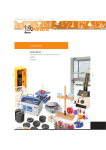
1
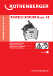
ROWELD ® ROFUSE Sani 160 www.rothenberger.com/manuals 5.4230 DEUTSCH Seite 3 Bedienungsanleitung bitte lesen und aufbewahren! Nicht wegwerfen! Bei Schäden durch Bedienungsfehler erlischt die Garantie! Technische Änderungen vorbehalten! ENGLISH page 16 Please read and retain these directions for use! Do not throw them away! The warranty does not cover damage caused by incorrect use of the equipment! Subject to technical modifications! FRANÇAIS page 29 Lire attentivement le mode d’emploi et le ranger à un endroit sûr! Ne pas le jeter! La garantie est annulée lors de dommages dûs à une manipulation erronée! Sous réserve de modifications techniques! NEDERLANDS bladzjde 42 Lees de handleiding zorgvuldig door en bewaar jaar goed! Niet weggooien! Bij schade door bedieningsfouten komt de garantieverlening te vervallen! Technische wihzigingen voorbehouden! CE-KONFORMITÄTSERKLÄRUNG Wir erklären in alleiniger Verantwortung, dass dieses Produkt mit den angegebenen Normen und Richtlinien übereinstimmt. EC-DECLARATION OF CONFORMITY We declare on our sole accountability that this product conforms to the standards and guidelines stated. DECLARATION CE DE CONFORMITÉ Nous déclarons sous notre propre responsabilité que ce produit est conforme aux normes et directives indiquées. CE-KONFORMITÄT/ CE-CONFORMITY/ CONFORMITÉ/ EC-KONFORMITEIT EG Richtlinie 89/336 EWG EG Niederspannungsrichtlinie 73/23 EWG Andere Normen/ Other Standards/ Autres normes/ Andere standaarden EN 292/1 EN 292/2 EN 60242 EC-KONFORMITEITSVERKLARING Wij verklaren in eigen verantwoordelijkheid dat dit product overeenstemt met de van toepassing zijnde normen en richtlijnen. ppa. Arnd Greding 2 Introduction Dear Customer: Thank you very much for purchasing our product. We are confident that it will meet your expectations. The ROWELD ROFUSE Sani 160 welding unit for electrofusion fittings is designed exclusively for joining PE discharge lines equipped with electrofusion fittings. The ROWELD ROFUSE Sani 160 was manufactured and checked according to state-of-the-art technology and widely recognized safety regulations and is equipped with the appropriate safety features. Before shipment, it was checked for operation reliability and safety. In the event of errors of handling or misuse, however, the following may be exposed to hazards: - the operator’s health, - the ROWELD® ROFUSE Sani 160 and other hardware of the operator, - the efficient work of the ROWELD ROFUSE Sani 160. All persons involved in the installation, operation, maintenance, and service of the ROWELD ROFUSE Sani 160 have to - be properly qualified, - operate the ROWELD ROFUSE Sani 160 only when observed, - read carefully and conform to the User’s Manual before working with the welding unit. Thank you. ENGLISH 17 1 Safety Instructions When using the ROWELD ROFUSE Sani 160 welding unit, comply with the following safety instruction to protect yourself from electrocution, injuries, and fire. Read and respect these instructions entirely before using the unit and keep the safety instructions in good order. 1.1 Keeping Your Work Area Orderly Keep the area you work in orderly and tidy. If you do not have a proper overview or if it is not orderly, this is in itself a potential cause for accidents. 1.2 Paying Attention to Your Work When working, monitor your actions and do not use the unit if you do not feel perfectly well. Pay attention to what you are doing at all time. 1.3 Securing the Pieces to Be Welded Use appropriate clamps to secure the fitting and the joint mechanically. By doing so, you also have your hands free to control the welding unit. 1.4 Ensuring a Compatible Environment Do not use the unit in a humid or wet environment or while it is raining. Do not use it close to flammable materials, such as liquids and gases. Avoid any contact with acids and other corrosive chemicals. 1.5 Cleaning the Welding Unit The ROWELD ROFUSE Sani 160 must not be sprayed with or immersed in water. Use a dry piece of cloth to remove dirt from the unit. 1.6 Checking the Welding Unit for Damage Each time before operating the welding unit, check safety features or possibly existing parts with minor damage for proper function. Make sure that the push-on connection terminals work properly, that contact is fully established, and that the contact surfaces are clean. All parts have to be installed correctly and properly conform to all conditions in order to be sure the unit works as intended. 1.7 Repairing the Unit Damaged safety features or functional parts should be properly repaired or changed by a qualified after-sales service. Therefore, the unit must never be repaired if not by a qualified and licensed specialist. Home-made repairs are strictly prohibited, as they may put you at a high risk of danger. 18 ENGLISH 1.8 Opening the Unit Do not remove the cover from the welding unit. It may be opened only by specialized staff of Rothenberger or another, properly authorized partner company. 1.9 Using Suitable Accessories Use only approved and properly labelled accessories (e.g., extension cables). 1.10 Using Genuine Parts On any rate, use only – if available – genuine and original accessories and spare parts. 1.11 Using the Appropriate Unit Make sure you use the unit that is appropriate for the intended work, and weld only fittings that are intended for this kind of application. The welding unit is suited exclusively for indoor installation applications. Use for buried pipeline construction applications is prohibited. 1.12 Unplugging the Power Supply Cord To avoid unnecessary risk, unplug the power supply cord from the mains socket when the unit is not used. 1.13 Storing the Welding Unit Safely Store the unit in a safe locale. Dry, lockable locales located at some height are particularly suited, the more so if they are out of the reach of children. 1.14 Protecting Yourself from Electrocution Connect the unit only to power supply socket equipped with an equipment grounding contact. In an environment that is humid or otherwise at risk of ground loops, the unit has to be operated with ground-leakage circuit breaker (30 mA false intensity threshold). 1.15 Only Qualified Operators The unit must be operated exclusively by properly trained specialized staff or by trainees if supervised by a competent person entitled to train others. Adolescents younger than 16 years of age may in no event be qualified to operate the unit. 1.16 Avoiding Unwanted Start of Operation Make sure that the unit is switched off before connecting it to the power supply. Carry it in such a way the none of the two buttons can be pressed inadvertently. ENGLISH 19 1.17 Improper Use of the Welding and Power Supply Cables Do not carry the ROWELD ROFUSE Sani 160 by its cord and do not pull the cord to unplug the unit from the socket. Protect cord and cables from heat, oil, and cutting edges. 1.18 Mains Power Supply EVU wiring regulations, VDE provisions, regulations for prevention of accidents, DIN / CE regulations, and applicable national codes have to be respected. Mains power fuse protection should be max. 10 A. Power supply to the unit has to be connected through a leakage current switch (earth-leakage circuit breaker rated at 30 mA false intensity). 1.19 Protecting Yourself from High Temperatures in the Fitting Caution! Be careful not to touch the fitting being welded or its immediate vicinity while welding is in progress and after it was finished. Temperatures in these pieces may be as high as up to 200 °C. 1.20 Protecting Yourself from the Electrical Voltage in the Fitting Caution! The voltage at the contact terminals of the fitting may be as high as up to 230 V during welding. Therefore, ensure at all times that neither the terminals nor the welding cables of the fitting are defective. While welding, never touch the contact terminals and their vicinity, and never remove the welding cable before having completely finished the welding process. 1.21 Keeping Pipes and Fittings Dry Never weld a fitting or pipes that are wet or filled with water. 20 ENGLISH 2 Service and Repair As the unit is used in applications that are sensitive to safety considerations, it may be serviced and repaired only on our premises or by partners who were specifically trained and authorized by us. Thus, constantly high standards of operation quality and safety are maintained. IMPORTANT! Non-compliance with this provision will dispense the manufacturer from any warranty and liability claims for the unit and any consequential damage. When serviced, the unit is automatically upgraded to the technical specifications with which the product is currently shipped, and we grant a threemonth functional warranty on the serviced unit. We recommend having the device serviced at least every twelve months. In Germany, keep in mind the follow-up check under BGV A2! Transport, Storage, Shipment The ROWELD ROFUSE Sani 160 is shipped in a cardboard box. Store the ROWELD ROFUSE Sani 160 in the box dry and protected from humidity. When shipped, the welding unit should be placed into the box at any time. 3 Principle of Operation The ROWELD ROFUSE Sani 160 allows joining with electrofusion fittings, discharge lines made of PE / PP and routed indoor, of the following makes: Geberit, Akatherm-Euro, Coes, Valsir, Wavinduo, and Vulcathene-Euro. The microprocessor-controlled welding unit ROWELD ROFUSE Sani 160 - controls and monitors the welding process in a fully automated fashion, - determines welding duration depending on the ambient temperature, - shows all information with three LEDs and a seven-segment display screen. Further Optional Accessories - Transport Case - Handheld Scraper ENGLISH 21 4 Operation 4.1 General Information on the Applied Procedure Electrofusion welding is characterized by thermal fusion of the outer surface of the pipe and the inner surface of the weld fitting by heating the heater coil incorporated into the fitting. In this process, the weld fitting shrinks and thereby creates the contact pressure needed to carry out the fusion of pipe and fitting surfaces. The automatic welding unit provides the electrical energy needed to perform this and control the energy supply according to certain parameters, such as ambient temperature. 4.2 Preparing the Welding Process In all cases, the relevant information supplied by the manufacturer of the pipes and the fittings have to be respected. First, both pipe butt have to be cut at right angles and level using appropriate tools. Then, using a chamfering and peeling tool or a handheld scraper, chamfer the edge and smoothen the pipe surface up to the length it will be inserted into the fitting. Then, the weld surface that is achieved by this process has to be de-fatted using an appropriate solvent (non-fibrous paper, spirit or suitable alcohol). Make sure nobody touches the cleansed surface and secure pipe and fitting for the welding operation. 4.3 Turning the Welding Unit On After connecting the power supply cord to 230V mains power, turn the welding unit on using the main switch. The unit then performs an autotest. All three LEDs are on briefly simultaneously to indicate that the unit is ready for operation. Furthermore, the seven-segment characters show the welding mode H0 for approximately 1 second. After this, both the LEDs and the screen characters change back to off. 4.4 H0 Connecting the Electro fusion Fitting Connect the connection terminals to the fitting and check for proper contact. The contact surfaces of the connection terminals and the fitting have to be clean. Dirty contacts may lead to improper welding and also to overheated and fused connection terminals. After the fitting was connected, the yellow LED (Fitting connected) is on. At the same time, the screen displays the welding time. By pressing the START key, the welding process can now be started. The welding time is counted down from about 80 s. To determine the welding duration that will be needed, the ambient temperature is taken into consideration to some extent, which may result in a welding time slightly longer or shorter than 80 s. 22 ENGLISH 80 4.5 Welding Process The welding process is monitored for its entire duration applying the welding parameters computed for the fitting. 4.6 End of Welding The welding process was completed successfully if the actual welding time shown on the screen is 0, the green LED (End) is on, and at the same time the audible signal can be heard twice. 4.7 Welding Aborted The welding process has caused errors if the red LED (Fault) is on and the audible signal buzzes intermittently. Additionally, an error code is displayed on the screen. An error has to be reacted to by pressing the STOP key. 4.8 Cooling Time The cooling time as given in the fitting manufacturer’s instructions has to be respected. Note that during that time, no external forces must be applied to the pipe fitting joint which is still warm. 4.9 Returning to the Start of Welding After welding is finished, disconnecting the welded fitting from the welding unit will cause the unit to return to the start of welding. An additional safety feature prevents a given electro fusion fitting from being welded twice inadvertently: after a properly completed or an aborted welding operation, the welding unit first has to be disconnected from the fitting to be ready for the next welding. ENGLISH 23 5 Self-Monitoring Functions Overview 5.1 System Error CAUTION! The welding unit has to be disconnected immediately from the power supply and the fitting. The auto-test has found an error in the system. The unit must no longer be operated and has to be turned in for check and repair. 5.2 Power Supply Failure The last welding is incomplete. The welding unit was disconnected from the power supply. This error has to be acknowledged by pressing the STOP key. 5.3 Overvoltage The input voltage is above 280 V. Adjust generator output voltage. 5.6 If this error is displayed during the unit’s auto-test, the temperature sensor is defective. Emergency Off The welding process has been interrupted by pressing the STOP key. 24 E6 Low or Excess Current The message is displayed if the there is a momentary current failure or if the current regulator is defective. 5.9 E5 Frequency Error The frequency of the input voltage is out of tolerance (40 Hz - 70 Hz). 5.8 E3 E4 Temperature Error or Temperature Sensor Defective The measured ambient temperature is outside the operating range of the welding unit, i.e., below – 5 °C or over + 40 °C. 5.7 E2 Low Voltage The input voltage is below 180 V. Adjust generator output voltage. 5.5 E1 No Contact There is no properly established electric contact between the welding unit and the fitting (check push-on terminal on fitting), or the heater coil is defective. 5.4 E0 ENGLISH E7 E8 5.10 Fitting Already Welded After welding was finished, the fitting was not disconnected from the welding unit, and the user attempted to weld the same fitting a second time. ENGLISH E9 25 6 Troubleshooting 6.1 Nothing happens after unit was turned on, it does not execute the auto-test Possible causes: · The unit is not connected to a mains power outlet. · The switch is defective. · The power supply line is faulty. · The unit is defective. · There is a general problem with the power supply. 6.2 After connecting the fitting, the yellow check LED does not light up, welding is impossible Possible causes: · The contact terminals are not properly connected. · The contact terminals are dirty. · The welding cable is faulty. · The weld fitting is defective. · The weld fitting is unsuitable. · The unit is defective. 26 ENGLISH 7 ROWELD® ROFUSE Sani 160 Technical Specifications Nominal Voltage 230 V Frequency 40 Hz - 70 Hz Power 1200 VA, 80 % ED Protection Index IP 44 Primary Current max. 10 A Ambient Temperature – 5 °C to + 40 °C Max. Output Current 5A Measuring Tolerance: Temperature ±5% Curent ±2% Unit Dimensions L = 120 mm, W = 160 mm, H = 77 mm Welding Cable Length 3m Power Supply Cord Length 2.5 m ENGLISH 27 8 Service and Repair Contact ROTHENBERGER Werkzeuge Productions GmbH Lilienthalstrasse 71 - 87 Phone: +49 (0)5602 9394 0 D 37235 Hess. Lichtenau Fax: +49 (0)5602 9394 36 Germany Web: www.rothenberger.com 9 Accessories and Spares for ROWELD® ROFUSE Sani 160 Aluminium Carrying Case ROWELD® ROFUSE Sani 160 User’s Manual Manual Scraper 10 Disposal Parts of the machine are reusable materials and can be recycled. Approved and certified recycling companies are available for this. For the environmentally friendly disposal of the non-recyclable parts (e.g. electronic scrap) please ask your responsible waste authority. 28 ENGLISH