1
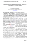
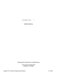
Dual Trace Oscilloscope USER MANUAL CONTENTS PAGE 1.GENERAL ┈ ┈ ┈ ┈┈ ┈┈ ┈┈ ┈ ┈ ┈ ┈┈ ┈┈ ┈ ┈ ┈ ┈ ┈ ┈┈ ┈┈ ┈ ┈ ┈ ┈ ┈ ┈┈ ┈┈ ┈ ┈ ┈ ┈ ┈ ┈┈ ┈┈ ┈1 1.1 Description┈ ┈ ┈ ┈ ┈ ┈ ┈ ┈ ┈ ┈ ┈ ┈ ┈ ┈ ┈ ┈ ┈ ┈ ┈ ┈ ┈ ┈ ┈ ┈ ┈ ┈ ┈ ┈ ┈ ┈ ┈ ┈ ┈ ┈ ┈ ┈ ┈ ┈ ┈ ┈ ┈ ┈1 1. 2 Features ┈ ┈ ┈ ┈ ┈ ┈┈ ┈ ┈ ┈ ┈ ┈ ┈ ┈ ┈┈ ┈ ┈ ┈ ┈ ┈ ┈ ┈ ┈┈ ┈ ┈ ┈ ┈ ┈ ┈ ┈ ┈┈ ┈ ┈ ┈ ┈ ┈ ┈ ┈ ┈┈ ┈1 2.TECHNICAL SPECIFICATIONS ┈ ┈ ┈ ┈ ┈ ┈ ┈ ┈┈ ┈┈ ┈ ┈ ┈ ┈ ┈ ┈┈ ┈ ┈ ┈ ┈ ┈ ┈ ┈ ┈┈ ┈ ┈ ┈ ┈ ┈ ┈┈ ┈ 2 3.PRECAUTIONS BEFORE OPERATING THE OSCILLOSCOPE ┈ ┈ ┈┈ ┈┈ ┈ ┈ ┈ ┈ ┈┈ ┈ ┈┈ ┈ ┈ ┈┈ ┈ ┈ ┈ ┈ 5 3.l Unpacking the Oscil loscope ┈ ┈ ┈ ┈ ┈ ┈ ┈ ┈ ┈ ┈ ┈ ┈ ┈ ┈ ┈ ┈ ┈ ┈ ┈ ┈ ┈ ┈ ┈ ┈ ┈ ┈ ┈ ┈ ┈ ┈ ┈ ┈ ┈ 5 3. 2 Checking t he Line voltage ┈ ┈ ┈ ┈ ┈ ┈ ┈ ┈ ┈ ┈ ┈ ┈ ┈ ┈ ┈ ┈ ┈ ┈ ┈ ┈ ┈ ┈ ┈ ┈ ┈ ┈ ┈ ┈ ┈ ┈ ┈ ┈ ┈ ┈ 5 3.3 Environment┈ ┈ ┈ ┈ ┈ ┈ ┈ ┈ ┈ ┈ ┈ ┈ ┈ ┈ ┈ ┈ ┈ ┈ ┈ ┈ ┈ ┈ ┈ ┈ ┈ ┈ ┈ ┈ ┈ ┈ ┈ ┈ ┈ ┈ ┈ ┈ ┈ ┈ ┈ 6 3. 4 Equipment Inst allation, and Operation┈ ┈ ┈ ┈ ┈ ┈ ┈ ┈ ┈ ┈ ┈ ┈ ┈ ┈ ┈ ┈ ┈ ┈ ┈ ┈ ┈ ┈ ┈ ┈ ┈ ┈ ┈ ┈ ┈ 6 3.5 CRT Intensity┈ ┈ ┈ ┈ ┈ ┈ ┈ ┈ ┈ ┈ ┈ ┈ ┈ ┈ ┈ ┈ ┈ ┈ ┈ ┈ ┈ ┈ ┈ ┈ ┈ ┈ ┈ ┈ ┈ ┈ ┈ ┈ ┈ ┈ ┈ ┈ ┈ ┈ 6 3. 6 Withstanding Voltages of Input Terminals┈ ┈ ┈ ┈ ┈ ┈ ┈ ┈ ┈ ┈ ┈ ┈ ┈ ┈ ┈ ┈ ┈ ┈ ┈ ┈ ┈ ┈ ┈ ┈ ┈ ┈ ┈ ┈ 6 4.OPERATION M ETHOD┈ ┈ ┈┈ ┈┈ ┈ ┈ ┈┈ ┈ ┈ ┈ ┈┈ ┈ ┈ ┈ ┈ ┈ ┈ ┈ ┈┈ ┈ ┈ ┈ ┈ ┈┈ ┈ ┈┈ ┈┈ ┈ ┈ ┈ ┈10 4. 1 Introduction of Front Panel┈ ┈ ┈ ┈ ┈ ┈ ┈ ┈ ┈ ┈ ┈ ┈ ┈ ┈ ┈ ┈ ┈ ┈ ┈ ┈ ┈ ┈┈ ┈ ┈ ┈ ┈ ┈ ┈┈ ┈┈ ┈ ┈ ┈ ┈ 10 4.2 Introduction of R ear Panel┈ ┈ ┈ ┈ ┈ ┈ ┈ ┈ ┈ ┈┈ ┈ ┈ ┈ ┈ ┈ ┈ ┈ ┈ ┈ ┈ ┈ ┈ ┈┈ ┈ ┈ ┈ ┈ ┈ ┈ ┈ ┈ ┈ ┈ ┈ 14 4.3 Basic Operation-Single channel Operat ion┈ ┈┈ ┈ ┈ ┈ ┈ ┈ ┈ ┈ ┈ ┈ ┈ ┈ ┈ ┈ ┈ ┈ ┈ ┈ ┈ ┈ ┈ ┈ ┈┈ ┈ ┈ ┈ ┈ 15 4.4 Dual-Channel Operation┈ ┈ ┈ ┈ ┈ ┈ ┈ ┈ ┈┈ ┈ ┈ ┈ ┈ ┈ ┈ ┈ ┈ ┈ ┈ ┈ ┈ ┈ ┈ ┈ ┈ ┈ ┈ ┈ ┈ ┈ ┈┈ ┈ ┈ ┈ ┈ 16 4.5 ADD Operation┈ ┈ ┈ ┈ ┈ ┈ ┈ ┈ ┈ ┈ ┈ ┈ ┈ ┈ ┈ ┈ ┈ ┈ ┈ ┈ ┈ ┈ ┈ ┈ ┈ ┈ ┈ ┈ ┈ ┈ ┈ ┈ ┈ ┈ ┈ ┈ ┈ ┈ ┈ 17 4. 6 Triggering┈ ┈ ┈ ┈ ┈ ┈ ┈ ┈ ┈ ┈ ┈ ┈ ┈ ┈ ┈ ┈ ┈ ┈ ┈ ┈ ┈ ┈ ┈ ┈ ┈ ┈ ┈ ┈ ┈ ┈ ┈ ┈ ┈ ┈ ┈ ┈ ┈ ┈ ┈ ┈ ┈ 17 4. 7 TIM E/D IV control┈ ┈ ┈ ┈ ┈ ┈ ┈ ┈ ┈ ┈ ┈ ┈ ┈ ┈ ┈ ┈ ┈ ┈ ┈ ┈ ┈ ┈ ┈ ┈ ┈ ┈ ┈ ┈ ┈ ┈ ┈ ┈ ┈ ┈ ┈ ┈ ┈ ┈ ┈ 20 4.8 Sweep Magnification ┈ ┈┈ ┈ ┈┈ ┈ ┈ ┈ ┈ ┈┈ ┈ ┈┈ ┈ ┈ ┈ ┈ ┈┈ ┈ ┈┈ ┈ ┈ ┈ ┈ ┈┈ ┈ ┈┈ ┈ ┈ ┈ ┈ ┈┈ 20 4. 9 X-Y Operat ion┈ ┈┈ ┈ ┈ ┈ ┈ ┈ ┈ ┈ ┈┈ ┈ ┈ ┈ ┈ ┈ ┈ ┈ ┈┈ ┈ ┈ ┈ ┈ ┈ ┈ ┈ ┈ ┈ ┈ ┈ ┈ ┈┈ ┈┈ ┈ ┈ ┈ ┈ 21 4.10 Calibration of Probe ┈ ┈ ┈ ┈ ┈┈ ┈ ┈ ┈ ┈ ┈ ┈┈ ┈┈ ┈ ┈ ┈ ┈ ┈ ┈ ┈ ┈┈ ┈ ┈ ┈ ┈ ┈ ┈ ┈ ┈┈ ┈ ┈ ┈ ┈ ┈ ┈ 22 4.11 DC BAL Adjustments┈ ┈ ┈ ┈ ┈ ┈ ┈ ┈┈ ┈ ┈ ┈ ┈ ┈ ┈┈ ┈ ┈ ┈ ┈ ┈ ┈ ┈ ┈┈ ┈ ┈ ┈ ┈ ┈ ┈┈ ┈ ┈ ┈ ┈ ┈ ┈ 22 5. MAINTENANCE┈ ┈ ┈ ┈ ┈ ┈ ┈ ┈ ┈ ┈ ┈ ┈ ┈ ┈ ┈ ┈ ┈ ┈ ┈ ┈ ┈ ┈ ┈ ┈ ┈ ┈ ┈ ┈ ┈ ┈ ┈ ┈ ┈ ┈ ┈ ┈ ┈ ┈ ┈ 23 5.1 Fuse replacement┈ ┈ ┈ ┈ ┈ ┈ ┈ ┈ ┈ ┈ ┈ ┈ ┈ ┈ ┈ ┈ ┈ ┈ ┈ ┈ ┈ ┈ ┈ ┈ ┈ ┈ ┈ ┈ ┈ ┈ ┈ ┈ ┈ ┈ ┈ ┈ ┈ ┈ ┈ ┈ 23 5.2 Cleaning┈ ┈ ┈ ┈ ┈ ┈ ┈ ┈ ┈ ┈ ┈ ┈ ┈ ┈ ┈ ┈ ┈ ┈ ┈ ┈ ┈ ┈ ┈ ┈ ┈ ┈ ┈ ┈ ┈ ┈ ┈ ┈ ┈ ┈ ┈ ┈ ┈ ┈ ┈ 23 6-9. COMPONENT TEST OPERATION┈┈ ┈┈ ┈┈┈┈┈ ┈┈┈┈┈┈ ┈ ┈┈┈┈ ┈┈ ┈ ┈┈ ┈┈ ┈┈┈ ┈┈ ┈┈ ┈┈┈ ┈┈24 10 . WAVEFORM CHART┈ ┈ ┈ ┈ ┈ ┈ ┈ ┈ ┈ ┈ ┈ ┈ ┈ ┈ ┈ ┈ ┈ ┈ ┈ ┈ ┈ ┈ ┈ ┈ ┈ ┈ ┈ ┈ ┈ ┈ ┈ ┈ ┈ ┈ ┈ ┈ ┈ ┈ ┈ 25 11 . BLOCK DIAGRAM┈ ┈ ┈ ┈ ┈ ┈ ┈ ┈ ┈ ┈ ┈ ┈ ┈ ┈ ┈ ┈ ┈ ┈ ┈ ┈ ┈ ┈ ┈ ┈ ┈ ┈ ┈ ┈ ┈ ┈ ┈ ┈ ┈ ┈ ┈ ┈ ┈ ┈ ┈ 26 I SAFETY TERMS AND SYMBOLS These terms may appear in this manual or on the product: ! WARNING. ! CAUTION . Warning statements identify condition or practices that could result in injury or loss of life . Caution statements i den tify conditions or practices that could result in damage to this product or other property. The following symbols may appear in this manual or on the product: ! DANGER High Voltage II ATTENTION refer to Manual Protective Conductor Terminal Earth(ground) Terminal 1.GENERAL 1.1 Description The 20MHz/ 25MHz/ 3 0MHz/40 MHz/50MHz family oscilloscope are dual-channel oscilloscope with m aximum sensitivi ty of 5mV/D IV. The time base provides a m aximum sweep time of 0.2 uS /DIV. When magnified by 10, the sweep speed is 20nS/DIV. Each of these oscilloscope employs a 6-inch rectangular type cathode-ray t ube with red i nternal graticule. These oscilloscopes are sturdy, easy to operate and exhibits high operational reliability. 1.2 Features 1) High intensity CRT with high acceleration voltage: The CRT is a high beam transmission, high intensity type with a high acceleration voltage of 2KV for 20MHz/25MHz /30MHz and 12KV for 40MHz/50MH z.It displ ays clear readable traces even at high sweep speeds. 2) A trigger level lock function which makes the triggering adjustment unnecessary. 3) Alternate triggering: Even an observation of t wo waveforms of different frequencies, the waveform of the each channel is stably triggered. 4) TV sync triggering: The oscilloscope has a sync separator circuit for triggering of TV-V and TV-H signals. 5) X-Y operat ion: Set the swi tch to X-Y.Then the instrument works as an X -Y oscill oscope. CH l can be applied as horizontal deflection (X-axis) while C H2 provide verti cal deflection(Y-axis). 1 2. TECHNICAL SPECIFICATIONS MODEL SPECIFICATIONS S ensitiv ity Ve rnier Vertical sensit ivity Freque ncy ba ndwidth 20 MHz OSCILLOSCOPE 30MHz OSCILLOSCOPE 40MHz OSCILLOSCOPE 50MHz OSCILLOSCOPE 5mV ~5V/DIV,10 steps in 1-2-5 sequence To l/2.5 o r less of pan el-indicated value. DC~20MHz DC~30MH z DC~4 0MHz DC~50MHz AC coupling: Low limit frequency10Hz. (With reference to 100KHz, 8DIV. Frequency response with-3dB.) Rise tim e Inpu t impe dance DC balance shift Linearity Vertical m odes Appro x.17.5nS Appr ox.11.7 nS Appr ox.8.75 nS Approx .7nS Approx .lM ohm //App rox.25 pF Adjust able on panel ≤ ±0.l D IV of amplitude cha nge wh en wa vef o rm of 2 DIV at grat icule ce nter is move d verti cally. CH1 :CH l single channel. CH2 :CH 2 sing le cha nnel. DUAL :C H1 an d CH2 are displayed. ALT o r CHOP selec table at any sweep ra te. ADD:CH1+CH 2 algeb raic ad dition. Cho pping repetiti on freq uency Inp ut coupling M aximu m inpu t volta ge Approx. 250KH z AC, GND, DC 400V (D C+AC peak),AC:fre quency lKHz or lowe r. When se t probe switch at l:1, the max imum effecti ve read out is 4 0Vpp( 14Vrm s at sin e wave ), Com mon m ode re jection ratio Iso lation between chan nels (At 5m V/DIV range) CH2 INV BAL. 2 or set probe switch at 1 0:1,th e maxim um effective readou t is 40 0Vpp(1 40Vrm s at sin e wave). 50:1 or better a t 50KH z sinu soidal wave. (When sensit ivities of CH 1 and C H 2. a re set e qually ) > 1000:l at 50K Hz >3 0:l at 15M Hz >3 0:1 at 25 MHz >30:1 a t 35 MHz Balance d point variati on: ≤ 1 DIV( Refere nce at c enter graticu le.) >30:1 a t 45 MHz MODEL SPECIFICATIONS 20 MHz OSCILLOSCOPE 30MHz OSCILLOSCOPE 40MHz OSCILLOSCOPE 50MHz OSCILLOSCOPE Triggerin g source CH 1, CH 2, LINE, E XT(CH 1 and CH 2 can be selected only when the vert ical mode is D UAL or ADD ) In ALT mode,i f the TRI G.ALT sw itch is pushed in,i t can be use for al ternate triggering of two different source. C ouplin g Slope Sensi tivity. A C:20Hz to ful l bandwi dth +/20Hz~2MHz:0.5DIV, TRIG-ALT:2 DIV, EXT:200mV 2~20MHz:1.5 DIV 20~30MHz:2.5 DIV 30~40M Hz:3.0 D IV 40~50MHz:3.0 DIV TRIG-ALT:3DIV, E XT: 800m V TV: Sync pulse more than 1 div(EXT:l V) Tr iggerin g mod es AUTO: Sweeps run in the free mode when no triggering input signal i s applied. (Applicable for repetitive signals of frequency 25Hz or over.) NORM: When no triggering signal is applied, the trace is in the ready state and not displayed. TV-V: Thi s set ting is used when observing the entire vertical picture of television si gnal . TV-H : This set ting is used when observing the entire horizontal picture of television signal. (Both TV-V and TV-H synchronize only when the synchronizing signal is negative) EXT tri ggering signa l input Input impedance Max. Input v oltage Sw eep tim e Swee p time accura cy Vern ier swe ep tim e control Swee p magn ification x10MAG sweep time accuracy L ineari ty Position shift caused by xl0MAG Se nsitivi ty X-Y Frequ ency ba ndwid th M ODE X-Y p hase differen ce Approx.: l M ohm/ /approx.25 pF 400V (DC+AC peak), AC:Frequency not higher than lKH z 0.2 uSec ~ 0.5 Sec / DIV, 20steps in 1-2-5 sequence +/-3% (10° C-35° C) ≤1/2.5 of panel-indicated value 10 tim es +/-5% (20nSec~50nSec are uncalibrated) +/-5% , xl0MAG: +/-10%(0.2s and 1 s ) Within 2 D IV.at CRT screen center Same as vertical axis.(X-axis:CH l input signal; Y-axis: CH 2 input si gnal .) DC to at least 500 K H z ≤3 at DC ~50 KH z 3 S PEC IFIC ATI ONS MO DEL Wave f orm Fr eque n cy C ALIB EATIO N Duty ra tio VO LTA GE O ut p u t vo l ta g e Output im pe d a nce Type Phosphor CRT 20MHz OSCILLOSCOPE 30MHz OSCILLOSCOPE 40 MHz OSCILLOSCOPE 50 MHz OSCILLOSCOPE P osit i ve -g oing square w ave Appro x. 1 kHz Wi thi n 48:52 2 Vp- p + /- 2% Approx. 1 K o hm 6- in ch rec tangu la r ty pe, in te rnal grati c u le P 31 Ac c el e ra ti o n volt ag e Approx. 2kV Appro x. 2 kV A pprox. 12 kV Approx. 12 kV Eff ect ive sc r ee n siz e 8x10 D IV( 1 DI V =10mm(0.39i n )) G r a ti c u l e I nt e rnal Tra c e r o tat i o n P rovide d Operating Environment Indoor use Altitud e up to 2000m Ambient temp erature : To satisfy spe cificat ions: l0 to 35 C(50 to 95 F) Maxim um ope rating ranges : 0 to40 C(32 to104 F ) Relativ e humi dity: 7 5%RH( max.)n on Condensin g Installa tion Category II Polluti on degr ee 2 Line Power Requirements Voltage : AC 110V/220V ± 10% Note :AC11 0V nee ds to prearran ge to m y facto ry. Freque ncy:50 Hz or 6 0 Hz Pow er consumptio n : Appro x.40VA,35W (max.) Mechanical Specifications Dim ensions : 310 W x150Hx 455 D(m m) Weight : Approx.8kg(l7.6lbs.) 4 Storage Temperature &Humidity Accessories -10 to 70 C,70%RH(ma ximum ) Po wer c ord┈ ┈ ┈ l User ma nual┈ ┈ ┈ 1 Pr obes┈ ┈ ┈ ┈ ┈ 2 3.PRECAUTIONS BEFORE OPERATING THE OSCILLOSCOPE 3.1 Unpacking the Oscilloscope The oscill oscope is shipped from the factory after being ful1y inspected and tested. Upon receiving the instrument, immediately unpack and inspect it for any dam ages that might have been sustained during transportati on. If any sign of damage is found, immediately notify the bearer and/or the dealer. 3.2 Checking the Line voltage These oscilloscopes wil l operate on AC 230V or 110V set by manufactory. Before connecting the pow er plug to an AC line outlet, make sure the voltage selector is set to the correct position corresponding to the line voltage. Note the oscilloscope may be damaged if it is connected to the wrong AC line voltage. ! WARN ING.To avo id electrical sho ck the p owe r cord protective grounding conductor mu st b e co nnected to ground. Replace the required fuses shown below. Line voltage ! Range Fuse AC 230V 207~253 T 0.5A 250V AC 110V 109~121 T 1.0A 250V WARNING. To avoid personal inju ry, disconnect t he power cord before removing the fuse holder 5 3.3 Environme nt The normal ambient temperature range of this instrument is 0 to 40 C(32 to 104 F).Operation of the instrument above this temperature range may cause damage to the ci rcuits. Do not use the inst rum ent in a place where strong magnetic or electric field exists, such fields may di sturb the measurement. 3.4 Equipm ent Installation, an d Opera tion Ensure there is proper ventilation for the hole vents in the oscilloscope case. If this equipment is used in a manner not specified by the manufacturer, the protect ion provi ded by the equipment may be impaired. 3.5 CRT Intensi ty To prevent permanent damage to the CRT phosphor, do not make the CRT trace excessi vely bright or leave the spot stati onary for an unreasonably l ong time. 3.6 Withstanding voltages of Input Terminals The withstanding voltages of the instrum ent i nput term inals and probe input terminals are as shown in the following table. Do not apply voltages higher than these l imits. When set probe switch at 1:1,the m aximum effective readout is 40Vpp (14Vrms at si ne wave).When set probe switch at10:1,the maximum effective readout is 400Vpp(140Vrm s at sine wave). Input terminal CH1, CH 2,inputs EXT TRLG IN input Probe inputs Maxi mum input voltage 400V (DC+AC peak) 400V (DC+AC peak) 600V (DC+AC peak) CAUTION. To ! avoi d in strumen t damage, do not exceed maximum inp ut voltages. Maximu m in put voltages mu st have frequen cies les s th an 1 KHz. If an AC volt age which is superimposed on a DC voltage is appl ied, the m aximum peak value of CH l and CH2 input voltages must not exceed + or - 300V.So for A C voltages with a mean val ue of zero volt the maximum peak to peak value is 600V. 6 Figure 4-1 34 35 31 37 32 36 30 29 28 27 25 26 24 O SC I LL OSCOP E COM P.T EST TRIGGER OF F ON N OR M C H2 TV - V L IN E TI M E /D IV 20 10 5 T R IG IN LEVEL uS 2 50 - 1 + - + ! 3 0 0V CAT Ⅱ MA X . 4 0 0V pk .5 .1 .2 .2 S .5 POSITION 1MΩ//25pF SL OP E 5 10 20 CAL E XT TV- H 2 1 50 5 1 mS 2 SWP.VAR C H1 A UT O HORIZONTAL X 10 MA G S O UR CE MOD E TR IG.A L T INPUT x10 UNCAL X- Y VERT ICAL V OLTS/D IV .1 .2 VOLT S/ DI V DC BAL 20 mv 2 20 mv 2 M OD E 5 VA R 50 V .5 1 DC BAL 10 5 .1 .2 P O SIT ION P O SI T ION 50 V .5 1 ALT C H OP CAL 10 5 5 VAR C H 2 IN V CH 1 CAL CH 2 CH1 X CH2 Y D UA L AC 1MΩ//25pF AC GN D A DD G ND CAL INTEN FOCUS 2V p-p TRACE ROTATION POWER 1MΩ//25pF DC DC ! ! 300 V CAT Ⅱ MA X. 4 0 0V pk 30 0V C AT Ⅱ MA X . 4 0 0V p k 1 KH z 1 2 3 4 6 8 7 10 9 13 11 12 15 16 17 14 18 19 20 21 22 7 33 34 35 32 OSC I LL OSCOP E 30 31 29 28 27 HORIZONTAL 24 TRIGGE R MOD E TR IG .A L T 8.8.8.8.8.8 S OUR CE C H1 A U TO TIME/DIV SWP.VAR POSITION 25 26 20 10 5 E XT T R IG IN L E VE L mS 1MΩ//25pF SL OP E 2 50 CAL LI NE 5 10 20 X 10 MA G C H2 TV - V TV- H 2 1 50 5 1 mS 2 N OR M - 1 + + - ! .5 .1 .2 3 00V CAT Ⅱ MA X . 4 0 0V pk .2 S .5 x10 UNCAL X- Y VE R TI CA L V OLTS/D IV .1 .2 V .5 1 VOLTS/DI V DC BAL 20 mv 2 DC BAL 20 mv 2 M OD E 5 VA R 50 V .5 1 10 5 .1 .2 P O SIT ION P O S I T ION 50 AL T CH OP CAL 10 5 5 VAR C H 2 IN V CH 1 CAL CH 2 CH1 X AC 1MΩ//25pF CAL INTEN FOCUS 2V p-p TRACE ROTATION C H2 Y DUA L AC GND A DD G ND DC POWER 1MΩ//25pF DC ! ! 300 V CAT Ⅱ MA X. 4 0 0 V pk 30 0V CAT Ⅱ MA X . 4 0 0V p k 1 KH z 1 8 2 3 4 6 7 8 9 10 11 12 13 14 15 16 17 18 19 20 21 22 Figure 4-2 RANGE LINE VOLTAGE SELEC TI ON (50/60Hz) 220V 198~242V 110 V 109~ 121V FUSE T 0 .5A 25 0V T 1A 250V ! WARNING TO AVOID ELECTRIC SHOCK THE POWER CORD PROTECTIVE GROUNDING P OWE R M A X. 35 WAT TS, 40 VA CONDUCTOR MUST B E CONNECTED TO GROUND. FOR CONTINUED FIRE PROTECTION. REPLACE ONLY WITH SPECIFIED TYPE AND RATED FU SE. NO OPERATOR SERVICEABLE COMPONENTS INSIDE. DO NOT REMOVE COVERS. REFER SERVICING TO QUALIFIED PERSONNEL. ~ AC ! ENSURE THE POWER IS REMOVED FROM THE INSTRUM ENT BEFORE REPLACING THE FUSE 38 39 9 4.OPERATION METHOD 4.1 lntroduction of Front Panel CRT:. POWER.... .................... .......(6) Main power switch of the instrument. When this switch is turned on, the LED (5)is also turned on. INTEN................... ..............(2) Controls the brightness of the spot or trace. FOCUS..... .................... .......(3) For focusing the trace to the sharpest im age. TRACE ROTATION............. .(4) Semi-fixed potentiometer for aligning the horizontal trace in paral lel with graticule l ines. FILTER................................(35) Fi lter for ease of waveform viewing. Vertical Axis: CH l (X)input.......................... (8) Vertical input terminal of CH 1. When in X-Y operation, X-axis input termi nal. CH 2(Y )input.......................... (20) Vertical input terminal of CH 2. When in X-Y operati on, Y-axis input terminal. AC-GND-DC..........................(10)(18) Switch for selecting connection mode between input signal and vertical amplifier. AC: AC coupling GND: Vertical am plifier input is grounded and input t erminals are disconnected. DC: DC coupling VOLTS/DIV..... .................... ....(7)(22) Select the vertical axis sensiti vity, from 5mV/DIV t o 5V/DIV in 10 ranges. 10 VARIABLE.......................(9)(21) Fine adjustment of sensitivity, with a factor of ≥1/2.5 of the indicated value. When in the CAL position, sensitivity is calibrated to indicated value. CH1 & CH2 DC BAL. (13)(17) These are used for the attenuator balance adjustment. See page 26 DC BAL adjustments for the details. POSITION.................(11)(19) Vertical positioning control of trace or spot. VERT MODE.....................(14) Select operation modes of CH l and CH 2 amplifiers. CH 1: The oscilloscope operates as a single-channel instrument with CH 1 alone CH 2: The oscilloscope operates as a single-channel instrument with CH 2 alone. DUAL: The oscilloscope operates as a dual-channel instrument both CH1 and CH2. ADD: The oscilloscope displays the algebraic sum (CH l+CH 2) or difference (CH 1 -CH 2)of the two signals. The pushed in state of CH2 INV (16) button is for the difference (CH l-CH 2). ALT/CHOP ...........................(12) When this switch is released in the dual-trace mode, the channel l and channel 2 inputs are alternately displayed (normally used at faster sweep speeds). When this switch is engaged in the dual-trace mode, the channel 1 and channel 2 inputs are chopped and displayed simultaneously (normally used at slower sweep speeds). CH 2 INV................................ (16) Inverts the CH2 input signal when the CH2 INV switch mode is pushed in The channel 2 input signal inADD mode and the channel 2 trigger signal pick off are also inverted. 11 Triggering: EXT TRIG IN input terminal...............(25) Input terminal i s used for external triggering signal. To use this terminal, set SOURCE sw itch(24)to the EXT position. SOURCE.................... (24) Select the internal triggering source si gnal , and the EXT TRIG IN input signal. C H l:When the VERT MODE swi tch (14)is set i n the DUAL or ADD state, select CH l for the internal triggering source signal. C H2:W hen the VERT MODE switch (14)is set i n the DUAL or ADD state, select CH 2 for the internal t riggering source Signal. LINE: To select the AC power line frequency si gnal as the tri ggering signal. EXT: The external signal applied through EXT TRIG IN input terminal(25)is used for t he external tri ggering source signal. TRIG. ALT.............(28) : W hen the V ERT MODE swit ch (14)is set in the DUAL or ADD state, and the SOURCE switch(24) is selected at CH l or C H2,w ith the engagement of the TRIG. ALT switch(28), it will alternately select C H 1 & CH 2 for the int ernal triggering source signal. SLOPE ...................(27) select the triggering slope. "+": Triggering occurs when the triggering signal crosses the triggeri ng level i n positive-going direct ion. " - ": Triggering occurs when the triggering signal crosses the triggering l evel in negative-going direction. 12 LEVEL...................(29) To display a synchronized stationary waveform and set a start point for the waveform. Towards: " + ":The triggeri ng level moves upward on the di splay waveform. Towards: " - ": The triggering level moves downward on the display waveform. TRIGGER MODE............ ....... ....(26) Select the desired trigger mode. AUTO :When no t riggering signal is applied or when triggering signal frequency i s less than 25Hz, sweep runs in the free run mode. NORM :When no triggering signal is applied, sweep is in a ready state and the trace is blanked out. Used primarily for observation of signal 25Hz. TV-V : T his setting is used when observi ng the entire vertical picture of television signal. TV-H: This setting is used when observing the entire horizontal pict ure of televisi on signal. (Both TV-V and TV-H synchroni ze only when the synchroni zing signal is negative.) FAMILY.........(33) Display a synchroninzde si gnal frequency (model s have thi s function onl y) . 13 Time Base TIME/DIV .............................(30) Sweep time ranges are available in 20 steps from 0.2 uS/DIV to 0.5 S/DIV. X-Y:This position is used w hen using the instrument as an X-Y oscilloscope. SW P. VAR ....................... ....... ....(31) Vernier control of sweep time. This cont rol works as CAL and t he sweep time is calibrated to the val ue indicated by TIME/DIV of weep can be varied continuously when Shaft is out of CAL position. Then the control is rotated in the direction of arrow to the full, the CAL state is produced and the sweep time is calibrated to t he value indicated by TIME/DIV. C ounterclockwise rotation t o the full delays the sweep by 2. 5 time or more. X10 MAG...... ............. ....... ........(32) When the button is pushed in, a magnification of l0 occurs. POSITION..........................(34) Horizontal positioning control of the t race or spot. Others CAL................(1) This terminal delivers the cali bration voltage of 2 Vp-p, approx.1 KHz, positive square wave. GND ...............(15) Ground term inal of oscill oscope mainframe. INPUT .............(36) Component test input terminal . O FF/O N.. ....... ...........(37) 4.2 1ntroduction of Rear Panel STUDS...... .................... ........(38) For laying the oscilloscope on its back to operate it in the upw ard posi tion. Also used to take up the pow er cord. AC Power input connect or .........(39) AC Power input socket. Connect the AC pow er cord (suppl ied)to this connector. 14 4.3 Basic Operation--Single-channel Operation Before connecting the power cord to an AC line outlet, make sure that the volt age selector on the rear panel of the i nstrument is correctly set for the AC line voltage. After ensuring the voltage setti ng, Set the switches and control s of the instrument as shown below: Item No Sett ing POWER INTEN (6) (2) FOCUS VERT MODE (3) (14) Mid-posi tion CH l ALT/ CHOP (12) Released (ALT) CH 2 INV (16) POSITION VOLTS/DIV (11)(19) (7)(22) VAR IABLE AC-GND-DC Disengage position (OFF) Mid-position (9)(21) Released Mid-posit ion 0.5V/DIV No (27) Setting + TRIG.ALT (28) Released TRIGG ER MODE (26) AUTO TIME/ DIV SWP.VER (30) (31) 0.5m Sec/DIV CAL position PO SITION Xl0 M AG LEVEL (34) Mid-position (32) (29) Released Locked CAL (clockwise position) (10)(18) GND (24) CH l SOURCE Item SLOPE After setting the switches and controls as mentioned, connect the power cord to the AC line outlet, and then continue as follows: 1) Engage the POWER switch and make sure that the power LED is turned on. In about 20 seconds,a trace will appear on the CRT screen. If no trace appears in about 60 seconds, counter check the switch and control setting. 2) Ad just the trace to an appropriate brightness and image with the INTEN contro1 and FOCUS control respectively. 15 3)Align the trace wit h the hori zont al center line of the graticul e by adjusting the CH1 POSITION control and TRACE ROTATION control (adjustable by screwdriver). 4)Connect the probe to the CH 1 INPUT terminal and apply the 2Vp-p CALIBRATOR signal to be probe tip. 5)Set t he AC-GND - DC switch to t he AC state. A waveform as shown in the figure 4-3 Will be di splayed on the CRT screen. 6)Adjust the FO CUS control so that the trace image appears sharpl y. 7)For signal viewing, set the VOLTS/D IV switch and TIME/DIV switch in appropriate positions so that signal waveform is displ ayed clearly. 8)Adjust the POSITIO N and POSITION controls in appropri ate posit ions so that the displayed waveform is aligned with t he graticule and voltage (Vp-p) and period (T)can be read conveniently. Figure 4-3 The above are the basic operating procedures of the osci lloscope. It is for single-channel operati on w ith Ch1. Singl e-channel operation with CH2 can also be achieved in a simil ar manner. Further operation methods are explained in the subsequent pages. 4.4 Dual-channel Operation Change the VE RT MODE sw itch to the DUAL states so that trace (CH 2) is also displ ayed (The explanation in the proceeding secti on is of CH1).At t his state of Procedure, the CH l trace is the square wave of the calibrator signal and the CH 2 Si gn al o f CH 1 trace is a straight li ne since no signal is applied to this channel yet. Now, apply the calibrator signal to the verti cal input terminal of C H 2 with the Si gn al o f CH 2 probe as is the case for CH 1. Set the AC-GND-DC switch to the AC state. Adjust vertical POSITION knobs (11)and (19)so that both channel signals are displayed as shown in Figure4 -4 16 Figure 4-4 When ALT / CHOP switch is released (A LT MOD E),the input signals applied respectively to CH l and CH2 appears on the screen alternativel y at each sweep. This setting is used when the sweep time is short in 2-channel observation. When ALT/CHOP switch is engaged(CHOP MODE),the input signals applied to CH 1 and CH 2 are switched at about 250KHz independent and at the same time appear on the screen. This setting is used when the sweep time is long in 2-channel observation When in the dual channel operation(DUAL or ADD mode),the CH l or CH2 signal must be selected for the triggering source signal by means of the SOURCE switch. If both CH l and CH 2 signals are in a synchronized relationship, both waveforms can be displayed stationary; if not, only the signal selected by the SOURCE switch can be stationary. If the TRIG. ALT push switch is engaged, both waveforms can be displayed stationary. 4.5 ADD Operation An algebrai c sum of the CH 1 and CH 2 signals can be displayed on the screen by sett ing the VERT MODE switch to t he ADD State. The displayed signal is the difference between CH l and CH 2 signals if the Ch 2 INV push switch is engaged. For accurate addition or subtraction, it is a prerequisite that the sensitivities of the tw o channels are adjusted accurately at the same value by means of the VARIABLE knobs. Vertical positioning can be made with the POSITION knob of eit her channel. In view of the linearity of the vertical amplifiers, it is m ost advantage to set both knobs in their mid-positions. 4.6 Triggering Proper triggering is essential for efficient operation of an oscill oscope. The user must be thoroughly familiar wi th the triggering functions and procedures. (1)Funct ions of M ODE swi tch: AUTO: When the AUTO switch is engaged, automatic sweep operat ion is selected. in automatic sweep operation, the sweep generator free runs to generate a sweep without a trigger signal. However, it automatically switches to triggered sweep operati on if an acceptable trigger source signal is present. The AUTO position is handy when first setting up the scope to observe a w aveform; It provides sweep for waveform observation until other control s can proper1y set. Once the controls are set, operation is often swit ch back to the NORM triggering mode, since i t is more sensitive. Aut omatic sweep must be used for DC measurements an signals of such low amplitude that they will not trigger the sweep. 17 NORM: The NO RM switch provides normal trigge red sweep operation . The sweep remains at rest unti l the selected trigger source signal crosses t he threshold level set by the TRIG LEVEL control . The trigger causes one sweep to be generated. after which sweep again remains at rest until triggered. In the NORM position, there will be no trace unless an adequate trigger signal is present -In t he ALT mode of dual trace operation with NORM sweep selected, there will be trace unless both channel 1and 2 signals are adequate for triggering. TV-V:Setting the MODE switch to the TV-V position permits selection of vertical sync pulses for sweep triggering when viewing composite video waveforms. Vertical sync pulses are select ed as trigger to permit viewing of vertical fields and frames of video. A sweep time of 2 ms/DIV is appropriate for viewing fields of video and 5ms/DIV for com plete frames(two interl aced fields)of video. TV - H:Set ting the MODE switch to the TV-H posit ion permits select ion of horizontal sync pulses for sweep triggering when viewing composite video waveforms. H orizontal sync pulses are selected as trigger to permit viewing of horizontal fields of video . A sweep time of about 10us/DIV is appropriate for di splaying lines of video. The SWP VA R control can be set to display the exact number of waveforms desired. T h is oscilloscope synchronizes with only ( - )polarity, that is, the sync pulses are negative and the video is positive as show n in Figure 4 - 5 (2)Functions of SOURCE switch: The displayed signal itself or a trigger signal which has a time relationship with the di splayed signal is required to be applied to the trigger circuit to display a stationary signal on the CRT screen. The SOURCE switch is used for selecting such a triggering source . Figure 4-5 CHl/CH2: The internal t rigger method which is used most commonly. The signal applied to the vertical input terminal is branched off from the preamplifier and is fed to the trigger circuit through t he VERT MODE switch. Si nce the t riggering signal is the measured signal itself, a stable wavefrom can be readily displayed on the CRT screen. W hen i n the DUAL or ADD operati on, t he signal selected by the SOURCE switch is used as the triggering source signa1. 18 Line: The AC power line frequency signal i s used as the triggering signal. This method i s effective when the measured signal has a relationship with the AC line frequency ,especially for measurements of low level AC noise of audio equipment, thyristor circuits, etc. EXT: The sweep is triggered with an external signal applied to the external trigger input terminal. An external signal which has a periodic relationship with respect to the measured signal is used. Since the measured signal is not used as the triggering signal, the waveforms can be displayed more independent than the measured signal. (3)Functions of TRIG LEVEL control and SLOPE switch: A sweep trigger is developed when the trigger source signal crosses a preset threshold level. Rotation of the TRIG LEVEL control varies the threshold level . In the "+"direction, the triggering threshold shifts to a more positive value ,and in the"-" direction, the triggering threshold shifts to a more negative val ue. When the control is centered, the threshold level is set at the approximate average of the signal used as the triggering source. The TRIG LEVEL control adjusts the start of the sweep to alm ost any desired point on a waveform. On sine wave signals, the phase at which sweep begins is variable. Note that if the TRIG LEVEL control is rotated toward its extreme+or- setting, no sweep will be developed in he NORM trigger mode because triggering threshold exceeds the peak amplitude of the sync signal. When the TRIG SLOPE switch is set to the (+)position(up), the sweep i s developed from the trigger source waveform as it crosses the threshold level in a positive-going direct ion. When the TRIG SLOPE control is set to the(-)position (down),a sweep trigger is developed form the trigger source waveform as it crosses the threshold level in a negative-going direction. This switch selects the slope (polarity) triggering signal as shown in Figure4-6 Slope"-"Range Level Slope"+"Range + - Figure 4--6 19 (4)Function of TRIG ALT switch: The TRIG ALT switch is used to select alternate triggering and alternate display when the DUAL-trace VERT MODE is select ed (the switch has on effect in the CH 1,CH 2, or ADD modes). In the alternate triggering mode (when dual-trace operation is selected),the trigger source alternates between channel l and channel 2 with each sweep. This is convenient for checking amplitudes, wave shape, or waveform period m easurements, and even permits simultaneous observation of two waveforms which are not-related in frequency or period. However, this setting is not suitable for phase or timing comparison measurements. For such measurements, both traces must be triggered by the same sync signal. When the CHOP and the TRIG ALT swit ches are both engaged during dual-trace operation, synchronization of the display is not possible because the chopping signal becomes the t rigger. Use the ALT mode by itself, or sel ect CH 1 or CH 2 as tri gger source. 4.7 TIME/DlV control Set the TIME / DIV control to display the desired number of cycles of th e waveform. If there are too many cycles displayed for good resol ution, switch to a faster sweep speed . If only a line is displayed, try a slower sweep speed. When the sweep speed is faster than the waveform being observed, only part of it will be displayed, which may appear as a straight line for a square wave or pulse waveform. 4.8 Sweep Magnification When a certain part of the displayed waveform is needed to be expanded time wise, a faster sweep speed may be used. However, if the required portion is apart from the starting point of the sweep, the required portion may run off the CRT screen. In such a case, push i n the x1 0 MAG button. When this has been done, the displayed waveform will be expanded 10 times to the right and le f t with the center of screen as the center of e xpansion. The sweep t ime during the magnificati on operation is as foll ows: (Value indicated by TIME/DIV switch)x1/10 Thus, the unmagnified maximum sweep speed(lu S e c/ DI V )c a n be increased wi th the magnification as follows: luSec / DIV x 1/10=100 nSec/DIV 20 10x magni fication Any part c an be covered by means of P OSITION con trol Figur e 4-7 4.9 X-Y Operation Y axis(CH2) Set the TIME/DIV switch to X-Y posi tion. Then the instrument works as an X-Y oscilloscope. Each input is applied to the instrument as follows. X axis (CH1) X-axis signal(horizontal axis signal) :CH 1 INPUT. Y-axis signal(vertical axi s signal) :CH 2 INPUT. Note: When high frequency signals are displayed in the X-Y operation, pay Figure 4-8 attention to the frequency bandwidths and phase difference between X and Y-axis. X-Y operation permits the osci lloscope to perform many measurem ents not possi ble with conventional sweep operation. The CRT display becomes an electronic graph of two instantaneous voltages. The display may be a direct comparison of the two voltages such as a vector scope display of video color bar patterns. How ever, the X-Y mode can be used to graph almost any dynamic characteristic if a transducer is used t o change the characteristic( frequency, temperature, velocity, et c.)into a voltage. One common application is frequency response measurements, where the Y-axis corresponds to signal amplitude and the X-axis corresponds to frequency. 1.Set the TIME/DIV control to the X -Y position (fully counterclockwise). In this mode, channel 1 becomes t he X-axis Input and channel 2 becomes the Y-axis input. 2.The X and Y positions are now adjusted using the horizontal POSITION and C H 2 POSITION controls respectively. 3.Adjust the amount of vertical (Y-axis) defl ection with the CH 2 VOLTS / DIV and VAR controls. 4.Adjust the amount of horizontal (X-axis) deflection wi th the CH 1 VOLTS/DIV and VAR controls. 21 4.10 Calibration of Probe As explained previously, the probe makes up a wide range attenuator. Unless phase compensation is properl y done, the displayed waveform is di stort ed causing measurement errors. Therefore ,the probe must be properly compensated before use. Connect the l0: l probe BNC to the INPUT terminal of CH1 or CH2 and set VOLTS/DIV switch at 50mV .Connect the Probe tip to the calibration voltage output terminal and adjust the compensation trimmer on probe for optimum square wave (minimum overshoot, rounding off and tilt ). Figure 4-9 (a)Correct compensation (b)Over compensat ion (c)Insuffi cient compensation 4.11 DC BAL Adjustments The ATT balance of the vertical axis can be made easily. (1) Set the input coupling switches of CH1 and CH2 to GND and set the TRIG MODE to AUTO. Then position the Base line to the center. (2) Turn the VLOTS/DIV switch to 5mV-10mV and adjust so that the line does not move. 22 5.MAINTENANCE WARNING T he following i nstructio ns are for use by qualified personnel only. To avoid electrica l shock, do not pe rform any servicing other than in the opera ting instructions unless you are quali fied to do so. 5.1 Fuse Replacement If the fuse blows, the power lam p indicators w ill not lig ht and the osci lloscope will n ot operat e. The fuse sho uld n ot normally open unle ss a pro blem h as deve loped i n the unit. Try to determine a nd corr ect the cause o f the bl own fu se. The rep1a ce only with a fuse of the correct ratin g and type (se e page 5) The fuse is l ocated on the rear p ane l (see fig. 4-2). WARNING ! For continued fire protection. Replace fuse onl y with 250V fuse of the specified type and rating, and disconnect power cord before replacing fuse. 5.2 Cleaning To clean the osci llosc ope, use a soft clot h da mpened in a solution of mild dete rgent and water. D o not spray cl eaner directly on to t he os cillo scope because it may l eak i nto t he ca binet and cau se damage. Do not use chemi cals cont aining benzin e, benzene, toluene, xylene, acet one, or si milar sol vent s. Do not use abrasi ve cleaners on any port ion o f the oscilloscope . 23 6.Component Test Operati on(Onl y Type T) The component test board deli vers a sin e volt a ge (50Hz o r 60H z) which i s applied across t he component under t est . The sine volt age across t he tes t object i s used for t he hori zontal defl ect ion(V)and voltage-drop(current th rough the t est object) is used for verti cal defl ect ion (I) of the osci ll oscope. By t hi s V-I characteristi c curve , the good or faul t of component is measured. 7.To set up the osci lloscope(Only Type T) for component test operati on,proceed as fol lows: 1. Turn TIME/DIV swi tch t o the X-Y posi tion and set bot h vert ical coupli ng swit ches to DC positi on as wel l as sett ing up the bot h V OLTS/DIV knob CH 1(X) t o 5V/ DIV,C H2(Y ) to 2V /DI V, then push t he COMP.TEST SW To TEST position. 2. Then horizontal bar graph of about 5~ 6 di v is displ a yed on the screen. 3. The posi ti on of graph is cont rolled with CH2 POSITION and H-POSITION. 4. Componet s may be directly hooked to testi ng code. Then waveform chart is di spl ayed on the screen. 8.Test condi tion 1. Resi tor,ca pacit or,coil, diode, zener or simpl e combinati on of the component s can be tested. 2. Test ing vol tage: approx. 9V ACp-p 3. Test ing frequency: 50/60Hz 4. Test ing current: approx. 0.6m A 9.<CAUTION> 1. Using t he component test functi on, don't appl y the si ngal to theCH1 and CH2 i nput be cause the oscil loscope doesn't operate i n t he component test mode. 2. Don't push X 10 MAG sw it ch because the bar wi ll be fatted. 3. Don't t e st t he l i ve circui t(operati ng t he power si gnal)c omponent . 24 10. WAVEFORM CHART Re r sister Capac itor Coil BIG BIG BIG MID MID MID SM ALL SM ALL Diode Zener SM ALL 25 11.BLOCK DIAGRAM 40/50MHz only +12kv CH 1 SIGNAL ONTPUT CH1 (X) INPUT CH 1 ATT CH 1 PREA MP CH1 TRIG(X-AXIS) PICKUP AMP CH2(Y) IN PUT CH 2 ATT VERT SIGNAL CH2 PREAM P VERTICAL MODE SWITCH V ERTICA L OU TPUT A MP SWITCHING LOGIC CRT CIRCUIT - H.V. CH 2 TRIG PICKUP AMP TRIG SIGNAL TRIG SWITC H H.V.SUPPLY X-AX IS SIGNAL CH 1 CH 2 TRIGGER INPUT AMP TRIGGER G ENERATOR EXT L INE AUTO CIRCUIT LINE TRIG (A)SWEEP GENE RATOR F REE RUN S IGNAL HORIZONTA L SWITCHING T O EACH BLOCK 2V p-p/1KHz HORIZON TAL OUTPUT AMP POW ER SUP PLY AC LINE 50/60H z CALIBRATOR SQUARE-WAVE 26 Specifications are subject to change without notice.