1
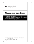
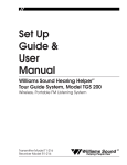
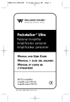
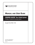
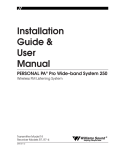
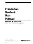
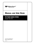
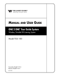
Set Up
Guide &
User
Manual
Hearing Helper ® PERSONAL FM System
Models PFM 300 & PFM 350
Wireless FM Listening System
Transmitter Model T30
Receiver Models R31, R32
MAN 072C
®
Williams
Sound
Helping People Hear
HEARING HELPER® PERSONAL FM SYSTEM, MODELS PFM 300 / PFM 350
INSTALLATION GUIDE & USER MANUAL
Contents
Page
SYSTEM OVERVIEW
4
SYSTEM COMPONENTS
5
USING THE T30 TRANSMITTER
6
USING THE PFM R32 RECEIVER
7
USING THE PFM R31 RECEIVER
8
BATTERY INFORMATION
10
USING YOUR PERSONAL FM SYSTEM WITH A HEARING AID
12
APPLICATIONS FOR VARIOUS HEARING LOSS LEVELS
13
IN CASE OF DIFFICULTY
14
CHANGING FREQUENCIES
15
WARRANTY
17
SYSTEM SPECIFICATIONS
18
ACOUSTIC SPECIFICATIONS
19
Williams
Sound ®
Helping People Hear
3
SYSTEM OVERVIEW
Thank you for purchasing the Hearing Helper® Personal FM System from Williams Sound
Corp. Anyone needing auditory assistance to overcome background noise, reverberation, or
distance from the sound source can benefit from the Personal FM System.
Your PFM System has two principal parts: the Transmitter and the Receiver. Much like a
miniature radio station, the Transmitter and microphone pick up the sounds you want to hear
and broadcast them over an FM radio signal. The receiver and earphone are used to pick up
the broadcast up to 100 feet away.
To avoid difficulties, please read through these instructions as you begin to use the system.
Then save them for questions that arise as you continue to use your Williams Sound Personal
FM System.
If you have problems with the PFM system, don’t hesitate to call us toll-free at
1-800-843-3544.
FIGURE 1: HOW THE PFM SYSTEM WORKS
FM Radio Signal
Speaker Uses Transmitter
With Microphone
Listeners use R31 or R32 Receivers with
Earphones, Headphones, Or Neckloop
The speaker wears the body-pack transmitter and a clip-on microphone. The
speaker’s voice is broadcast as an FM radio signal over a distance of 100-150 feet
(30-45 m). Listeners use the pocket receiver and earphone or headphone to hear the
speaker’s voice directly, with reduced background noise. A neckloop telecoil
coupler allows the system to be used with telecoil (T-Switch) equipped hearing aids.
4
Williams
Sound ®
Helping People Hear
SYSTEM COMPONENTS
Body Pack Transmitter (PFM T30) with (2) AA batteries (BAT 001)
Lavalier microphone (MIC 090)
Mini earphone (EAR 013)
Soft Nylon System Carry Case (CCS 020)
(2) Belt clip cases (CCS 021)
Instructions (MAN 072)
PFM System 300 Only:
Personal FM Receiver (PFM R32) with (2) AA batteries (BAT 001)
PFM System 350 Only:
Personal FM Receiver (PFM R31) with Plug Mount Microphone (MIC 014)
and (2) AA batteries (BAT 001)
FIGURE 2: SYSTEM COMPONENTS
Microphone
Earphone
Earphone
Microphone
Mic
Volume
On/Off &
FM Volume
On/Off Switch
On/Off &
FM Volume
Mic Jack
Williams Sound
Williams
Sound
Hearing Helper
Williams Sound
Williams
Sound
®
Hearing Helper
®
Hearing Helper
Williams Sound
Williams
Sound
®
Hearing Helper
®
Hearing Helper
®
Hearing Helper
®
T30 Transmitter
R32 Receiver
R31 Receiver
(PFM 300 & 350 Systems)
(PFM 300 System)
(PFM 350 System)
Williams
Sound ®
Helping People Hear
5
USING THE T30 TRANSMITTER
1. Make sure there are two charged AA batteries in the transmitter. If batteries are not
installed, see Battery Information on page 10.
2. Plug the microphone cord into the “Mic” jack on top of the Transmitter.
FIG. 3: T30 TRANSMITTER TOP VIEW
Off
Mic
Mic
Jack
On
FM
On/Off
Switch
Williams Sound FM
3. Place the Transmitter in the belt clip case provided.
4. Turn the power switch on top of the Transmitter to “On.”
5. Clip the microphone onto a collar, lapel, or tie. It should be as close to the speaker’s
mouth as is practical. (See Figure 4.)
The transmitter can be placed in a pants pocket, or clipped onto a belt or
waistband. Make sure the Transmitter is turned OFF when not in use.
FIGURE 4: CORRECT MICROPHONE PLACEMENT
Yes
Yes
No
The PFM System 300/350 comes with an omnidirectional, lapel-clip style microphone. It
should be clipped to a collar, lapel, tie, or neckline as close to the mouth as possible and
centered on the body as shown.
Note On The Transmitter Antenna:
The microphone cord is the transmitting antenna. Do not bunch up the cord or wrap it around
the transmitter. For maximum range, the cord should hang as straight as possible.
6
Williams
Sound ®
Helping People Hear
USING THE PFM R32 RECEIVER (PFM 300):
Receiver model PFM R32 has a single volume control and an earphone output jack.
1. Make sure there are two charged AA batteries in the Receiver. If batteries are not
installed, see Battery Information on page 10.
2. Plug the earphone or headphone into the “Ear” jack on top of the Receiver.
FIGURE 5: R32 RECEIVER TOP VIEW
Earphone
Jack
FM Indicator
FM
EAR
FM
Off
On
Indicator
On
Volume
Control
Max
3. Turn the power on by rotating the volume control knob on top of the Receiver.
4. Place the earphone in your ear.
5. Choose the correct channel using the right switch on the R32’s back panel.
Unless you have changed the Transmitter channel, set the receiver to channel 1. If the
Transmitter is on and tuned to channel 1, the FM Indicator light on the R32 will light.
FIGURE 6: RECEIVER TONE & CHANNEL CONTROLS
TONE
Lo Mid Hi
Channel
CH1 CH2
6. Adjust the receiver volume control to a comfortable listening level.
You should be able to hear someone speaking into the Transmitter microphone.
7. Adjust the receiver tone control to your needs. Lo – more low frequencies;
Mid – some low frequency cut; Hi – maximum low frequency cut, emphasizes higher
frequencies. (See Figure 6.)
8. Place the Receiver in the belt clip case provided. The Receiver can be placed in a pants
pocket, or clipped onto a belt, harness, or waistband.
Notes:
The earphone cord is the receiving antenna. Do not bunch up the cord or wrap it around the
receiver. For best reception, the cord should hang as straight as possible. Make sure the
Receiver is turned OFF when not in use. The channel selector can be used to switch between
an individual and a group channel.
Williams
Sound ®
Helping People Hear
7
USING THE PFM R31 RECEIVER (PFM 350):
Receiver model PFM R31 has two volume control knobs (one for the FM signal, one for
environmental sounds), a microphone input jack, and an earphone output jack.
1. Make sure there are two charged AA batteries in the Receiver. If batteries are not
installed, see Battery Information on page 10.
2. Insert the small Plug Mount Microphone (MIC 014) into the “Mic” jack on top of the
R31 Receiver.
FIGURE 7: R31 TOP VIEW
FM Volume
On Indicator
Mic Jack
FM
EAR
FM
Indicator
FM
Off
On
Mic
Max Min
MIC
Max
Mic
Volume
Mic
Jack
3. Plug the earphone or headphone into the “Ear” jack on top of the Receiver.
4. Turn the power on by rotating the taller “FM” volume control on top of the Receiver.
5. Place the earphone in your ear.
FIGURE 8: RECEIVER TONE & CHANNEL CONTROLS
TONE
Lo Mid Hi
Channel
CH1 CH2
6. Choose the correct channel using the right switch on the R31’s back panel. If the
Transmitter is on and tuned to channel 1, the FM Indicator light on the R31 will light.
7. Adjust the receiver tone control to your needs. Lo – more low frequencies;
Mid – some low frequency cut; Hi – maximum low frequency cut, emphasizes higher
frequencies. (See Figure 6.)
8. Place the Receiver in the belt clip case provided. The Receiver can be placed in a pants
pocket, or clipped onto a belt, harness, or waistband.
8
Williams
Sound ®
Helping People Hear
Notes:
The earphone cord is the receiving antenna. Do not bunch up the cord or wrap it around the
receiver. For best reception, the cord should hang as straight as possible. Make sure the
Receiver is turned OFF when not in use. The channel selector can be used to switch between
an individual and a group channel.
Adjusting The R31 Volume Controls
1. Adjust the taller “FM” volume control to a comfortable listening level. You should be
able to hear someone speaking into the Transmitter microphone.
2. Now adjust the shorter “Mic” volume control until you can hear sounds picked up by the
environmental microphone on top of the receiver.
3. Adjust the two volume controls for a comfortable mix of FM and environmental sounds.
You will normally want to have the FM signal louder than the environmental Mic
signal to avoid picking up extra background noise. If no environmental sounds are
desired, turn the “Mic” control fully to “Min”. If you want to hear nearby
conversation or your own voice, turn the “Mic” control up.
Williams
Sound ®
Helping People Hear
9
BATTERY INFORMATION
INSTALLATION
Open the battery compartment using a coin in the slot in the bottom of the receiver. Press the
batteries into place, observing proper battery polarity. Incorrect insertion of the battery is
difficult, and may cause both mechanical and electrical damage to transmitters or receivers
not covered by the 5 year warranty. Units will not work with the battery incorrectly installed.
FIGURE 9:
INSTALLATION OF BATTERIES
Rear of Transmitter
or Receiver
Battery
Compartment
Note Proper
Polarity
–
+
+
–
Pry
Slot
DISPOSABLE BATTERIES
In normal use, two AA 1.5 V alkaline batteries will last about 12 hours in the T30
Transmitter and approximately 80 hours in the R31 and R32 Receivers, respectively.
If the sound becomes weak or distorted, replace the battery. The indicator light may still be
on, even with a battery that is weak. Do not leave dead batteries in the receivers. Battery
corrosion is not covered by the Williams Sound five year warranty.
RECHARGEABLE BATTERIES
The PFM 300 and PFM 350 Systems can use rechargeable AA batteries (BAT 026). On an
overnight charge, these NiMH batteries are designed to operate a T30 Transmitter for
approximately 10 hours, and R31 and R32 Receivers for 50 and 60 hours, respectively.
The battery installed in the receiver may be recharged in the receiver only if it is a Nickel
Cadmium battery, and only if the Williams Sound CHG 200A charger is used. Damage from
improper charging is not covered by the Williams Sound five year warranty. For charging
directions, see figure 9.
!! IMPORTANT WARNINGS !!
DO NOT ATTEMPT TO RECHARGE ZINC CARBON (“HEAVY DUTY”), ALKALINE, OR LITHIUM BATTERIES!
DO NOT ATTEMPT TO RECHARGE DISPOSABLE BATTERIES! These batteries may heat up and
explode, causing possible injury and damage to the equipment.
Avoid shorting the plus and minus battery terminals together with metal objects. Battery damage
and burns can result!
Use only Williams Sound Supplied chargers and batteries!
10
Williams
Sound ®
Helping People Hear
FIGURE 10: USING THE OPTIONAL CHG 200A BATTERY CHARGER TO CHARGE TRANSMITTERS AND RECEIVERS
Step 1:
Plug the CHG 200’s power supply into
the Power Input on the charger’s side and
a standard AC wall outlet.
Step 2:
Route the power cord around the Cord
Hook (see figure at right). This will
minimize strain on the cord and jack and
insure that the power cord is not detached
during charging.
Step 3:
Make sure the receivers/transmitters to be
charged are turned OFF.
Step 4:
Place the receivers/transmitters in the
slots so that the CHG 200’s Charging
Pins and receiver’s side panel contacts
are coupled. Make sure that the charging
contact holes line up with the charging
pins. The receivers should drop easily
into the slots. DO NOT FORCE THEM
IN BACKWARDS.
Step 5:
Charging
Contact Holes
Charging
Indicators
Charging
Pins
The Charging Indicators will light,
indicating that charging is in process.
It takes 14–16 hours to fully charge the
batteries. Remove the receivers when
charging is completed.
Cord Hook
Power Input
FURTHER SUGGESTIONS
Receivers and Transmitters SHOULD NOT be left charging continuously when not in use.
Receivers should always be turned OFF while charging.
It’s best to allow the batteries to fully discharge before charging.
If the batteries are near end of life and the LED turns off while the receiver is operating, this is an
indication to change or recharge your batteries. Approximately one hour of battery life remains.
Repeatedly charging the batteries after short periods of use (1-2 hours) will shorten battery life.
Rechargeable batteries will need to be replaced after 1–2 years of use.
!! WARNING !!
DO NOT ATTEMPT TO RECHARGE DISPOSABLE BATTERIES!
The batteries may heat up and burst, causing possible injury and damage to the equipment.
Avoid shorting the plus and minus battery terminals together with metal objects. Battery damage and
burns can result!
Use only Williams Sound supplied chargers and batteries.
Williams
Sound ®
Helping People Hear
11
USING YOUR PERSONAL FM SYSTEM WITH A HEARING AID
If you have a hearing aid equipped with a Telecoil (T-Switch), you can use a Neckloop
(NKL 003–children’s size, or NKL 001–adult’s size) or Silhouette coil (INC 005 WC) to
magnetically couple the signal from the PFM Receiver into your hearing aid.
The Neckloop plugs into the earphone jack of the receiver. Turn the switch to the “T”
position on your hearing aid and adjust the volume control on the receiver to a comfortable
level. If you have two hearing aids with telecoils, the signal will couple into both hearing aids
(when using INC 006 WC).
Direct Audio Input cords can be used with compatible hearing aids as well as with Cochlear
Implant Processors. If your hearing aid has a direct audio input boot, you can obtain a cord
from your hearing aid manufacturer to plug directly into the PFM receiver. The cord should
have a 3.5 mm plug.
12
Williams
Sound ®
Helping People Hear
APPLICATIONS FOR VARIOUS HEARING LOSS LEVELS
The Personal FM is designed to provide hearing assistance for anyone when background
noise or distance from the sound source make listening difficult. The microphone and
transmitter are placed close to the desired sound source to help minimize background noise
and to effectively eliminate the distance between the listener and the sound source. Because
hearing ability varies, three categories of amplification have been delineated:
NO HEARING LOSS – LOW AMPLIFICATION
Among Low Amplification applications are classroom and similar uses. The PFM System
can be used with headphones or earphones for Central Auditory Processing Disorders,
Learning Disabilities, or Attention Deficit Disorders. The PFM System is used primarily to
boost speech sounds above other background noises, making it easier for the listener to focus
on what is being said. The optional Rugged Headphone (HED 022–children’s size, and HED
021–adult’s size) are recommended for this application. The EAR 013 Single Mini Earphone,
EAR 008 Surround Earphone, or EAR 014 Dual Mini Earphone can also be used.
MILD – MODERATE HEARING LOSS
These applications include the classroom, TV listening, car riding, and one-on-one
conversations. The PFM System can be used with the Single or Dual Mini Earphone
(EAR 013 or EAR 014) for moderate amplification fittings. The Button Receiver Earphone
(EAR 012 WC) is also available for use with a snap-on custom earmold. The PFM System is
also suitable for temporary mild hearing loss due to Otitis Media. The Rugged Headphones
(HED 021) or Surround Earphone (EAR 022 or EAR 008) are recommended since they do
not enter the ear canal.
SEVERE – PROFOUND HEARING LOSS
These applications include the classroom, TV listening, car riding, and one-on-one
conversations. For severe to profound hearing loss, the PERSONAL FM System should be
used in conjunction with a hearing aid. A Neckloop can be used with hearing aids that have a
telecoil. An adaptor cord can be used with hearing aids that have direct audio input.
Williams
Sound ®
Helping People Hear
13
IN CASE OF DIFFICULTY
If your Personal FM System is not working, check the following:
1. Make sure the batteries are fresh or completely charged and that the “plus” and “minus”
terminals are installed correctly.
2. If the rechargeable batteries will only work for a short period of time (less than 1 hour)
even after they are fully charged, they must be regenerated. Leave them in the receiver or
transmitter with the unit turned on, for 5 - 6 hours. Then turn receiver or transmitter off,
place it in the charger, and charge for 14 - 16 hours. This should restore normal battery
life. Rechargeable batteries will gradually lose their capacity over time and should be
replaced every year.
3. Make sure the microphone is plugged into the T30 Transmitter and the earphone is
plugged into the Receiver.
4. If you have the PFM System 350, make sure the R31 Receiver’s plug mount microphone
IS NOT plugged into the Transmitter.
5. If you’re using the PFM System 350 with the PFM R31 Receiver, make sure that the
earphone has been plugged into the earphone jack and not into the R31 Receiver’s
microphone jack.
6. Move the Transmitter and Receiver closer together. You may be out of range. When
using the system indoors, it’s normal for the signal to momentarily disappear in certain
locations. This is called a “drop-out.” Moving a few feet will restore the signal.
7. Make sure that the Transmitter and Receivers are tuned to the same channel. The units
have stickers inside the back cover identifying the channel. Unless the Transmitter
channel has been changed, set the Receiver to channel 1.
8. Do not try to use more than one Transmitter on the same channel in close proximity to
each other. MORE THAN ONE TRANSMITTER ON THE SAME CHANNEL WILL
RESULT IN INTERFERENCE IF THEY ARE CLOSE TOGETHER. Keep the systems
50 - 100 feet apart or use separate channels for each system used.
9. If you are still hearing interference on the Receivers, turn the Transmitter off and listen
with a receiver. If you hear the interference with the Transmitter off, you need to change
to a clear channel. See the re-tuning instructions.
10. If problems remain, contact your dealer for further help. Or call Williams Sound toll-free
at 1-800-843-3544.
14
Williams
Sound ®
Helping People Hear
CHANGING FREQUENCIES
If you experience FM signal interference, you can easily adjust your transmitter and receivers
to a use different frequencies. Your first channel choice should be Channel G (75.7 MHz).
This matches channel 2 on the R31 and R32 Receivers.
CHANGING THE PFM T30 TRANSMITTER FREQUENCY
1. Open the battery compartment using a coin in the slot in the bottom of the transmitter.
Remove the batteries.
2. Lift the flap up and to your left. The back of the Transmitter case will open like a book,
exposing the circuit board.
3. Use the diagram in Figure 11 to locate the channel selector switches.
FIGURE 11: TRANSMITTER FREQUENCY CHANGE INFORMATION
Switches set for 72.9 MHz
1 2 3 4 5 6 7 8
UP (OFF) DOWN (ON)
Switch Settings
Batteries
T30 Transmitter
CH (MHz) 1
2
3
4
5
6
7
A
72.1
DN
UP
DN
UP
DN
DN
DN DN
8
B
72.3
DN
UP
DN
UP
UP
DN
DN DN
C
72.5
DN
UP
DN
UP
DN
DN
UP DN
D
72.7
DN
UP
DN
UP
UP
DN
UP DN
E
72.9
DN
UP
DN
UP
DN
DN
DN UP
F
75.5
UP
UP
DN
UP
UP
DN
DN DN
G
75.7
UP
UP
DN
UP
DN
DN
UP DN
H
75.9
UP
UP
DN
UP
UP
DN
UP DN
I
74.7
UP
DN
DN
UP
UP
DN
DN UP
J
75.3
UP
UP
DN
UP
DN
DN
DN DN
4. Use the tip of a paper clip or a small screwdriver (not a pencil point) to move the
switches to correspond with the switch positions on the programming chart in Figure 11.
Remember, your first choice should be G (75.7 MHz). If you must use another channel,
select a frequency at least two channels away from the one on which you are
experiencing interference. Do not touch any other adjustments.
5. Reinstall the batteries, then close the back of the Transmitter.
6. Plug the microphone in and turn the Transmitter on to provide a tuning signal for the receivers.
7. Change the receivers to channel 2. If you set the transmitter to any channel other than E or G,
you will need to re-tune the receivers. See the next section for receiver tuning instructions.
Note:
Many PFM users reserve Channel 1 on their receivers to match large area FM systems set to
Channel E (72.9 MHz). They set their T30 Transmitter to Channel G (75.7 MHz) to allow
receiver users to switch between channels depending on the listening situation.
Williams
Sound ®
Helping People Hear
15
TUNING THE PFM R31 & R32 RECEIVERS
Tuning for the R31 and R32 Receivers is determined by tuning coils, and is stabilized by
phase-locked-loop circuitry. A plastic tuning wrench (PLT 005) is needed to adjust the
receiver tuning coil.
1. Use the Transmitter as a tuning signal source. Have someone speak into the microphone
so you have something to listen to.
2. Keep the Transmitter and Receiver about 15 - 20 feet apart while tuning. The receiver
must be tuned under weak signal conditions.
3. Open the battery compartment using a coin in the slot in the bottom of the transmitter.
Pull up the receiver battery flap to open the receiver back like a book. This will expose
the circuit board.
4. Move the channel selector switch to channel 2 (right position).
5. Use Figure 12 below to locate the tuning coils. Use the earphone supplied with the
receiver to listen for the transmitter signal while you slowly and gently rotate the tuning
slugs inside the tuning coil with the tuning wrench. Adjust the tuning coil for channel 2
slowly and carefully. Do not press down on the tuning slug. Adjust for maximum signal.
5. Re-tune all the receivers and mark the new frequency inside the case for future reference.
FIGURE 12: LOCATION OF RECEIVER TUNING COILS
Channel 1 Tuning Coil
Channel 2
Tuning Coil
Batteries
Channel Selector Switch
R31/R32 Receiver
16
Williams
Sound ®
Helping People Hear
WARRANTY
The Williams Sound T30 Transmitter, R31 and R32 Receivers are engineered and designed
to provide you with many years of reliable service. Williams Sound warrants it against
defects in materials and workmanship for FIVE (5) years EXCEPT FOR earphones,
headphones, rechargeable batteries, chargers, cables, antennas, carry cases, and all other
accessory products. Accessory products carry a 90 day warranty.
If the product fails within the specified warranty period, Williams Sound will determine
whether to repair or replace the defective equipment. This warranty does not apply to
physical damage, products that have been abused or mis-used, or modified.
If you experience difficulty with your system, call Toll-Free for Customer Assistance:
1-800-843-3544.
If it is necessary to return the system for service, your Customer Service Representative will
give you a Return Authorization Number (RA) and shipping instructions.
Pack the system carefully and send it to:
Williams Sound Corp.
Attn: Repair Dept.
10321 W. 70th St.
Eden Prairie, MN 55344
Your warranty becomes effective the date you purchase your system. Your returned warranty
card is our way of knowing when your warranty begins. It also gives us important
information about your system including the serial number. This information will help us
serve you better in the future. Please take a moment to complete the warranty card. Thank
you.
Williams
Sound ®
Helping People Hear
17
TECHNICAL SPECIFICATIONS
FM TRANSMITTER, MODEL PFM T30
Dimensions:
Weight:
Color:
Battery Type:
Operating Freq’s:
Stability:
Modulation:
RF Output:
FCC ID:
Freq Response:
Signal–Noise Ratio:
Auto Gain Control:
Transmit Antenna:
Microphone:
Controls:
Mic Connector:
3-5/8" L x 2-3/8" W x 7/8" H (92.1 mm x 60.3 mm x 22.2 mm)
4.4 oz (125 g) with battery
Royal blue, shatter-resistant polypropylene
Two (2) AA 1.5 V Non-rechargeable Alkaline batteries
(BAT 001), 70 mA nominal current drain, 12 hours approx. life
(OR)
Two (2) AA 1.5 V NiMH Rechargeable batteries (BAT 026),
70 mA nominal current drain, 10 hours per charge approx., recharges in 14–16
hours, uses CHG 200 Charger
Selectable, 10 channels, 72.1 – 75.9 MHz, internal DIP switch
+ .005%, frequency synthesized, crystal reference, PLL
Wide-band FM, 75 kHz, 75 µS pre-emphasis
8000 µV/m at 30 m, max., 40 mW typical
CNM T30
100 to 10 kHz, + 3 dB at 1% max. THD
55 - 60 dB, with R31 or R32 Receiver
40 dB range, 30 mV threshold
Integral with 40" microphone cord
Omnidirectional condenser, Lavalier-type, 40" cord,
3.5 mm mono phone plug (MIC 090)
On/Off switch, slide-type
3.5 mm mono phone jack
RECEIVER, MODELS PFM R31 & PFM R32
Dimensions and
Weight:
Color:
Battery Type:
FCC ID:
Operating Freq’s:
FM Deviation:
AFC Range:
Sensitivity:
Freq Response:
Signal–Noise Ratio:
Receive Antenna:
Audio Output:
Output Connector:
Squelch:
Carrier Detect Ind:
Controls:
Note:
3-5/8" L x 2-3/8" W x 7/8" H (92.1 mm x 60.3 mm x 22.2 mm)
4.6 oz (130 g) with batteries
Royal blue, shatter-resistant polypropylene
Two (2) AA 1.5 V non-rechargeable Alkaline batteries
(BAT 001), 14 mA nom. current drain, 80 hours approx. life
(OR)
Two (2) AA 1.5 V NiMH rechargeable batteries (BAT 026), 14 mA nominal
current drain, 50 hours per charge approx., recharges in 14–16 hours, uses
CHG 200 Charger
CNM R31
Pre-Tuned, Field–tuneable, 72 MHz - 76 MHz.
Pre-set channels are E (72.9 MHz) and G (75.7 MHz)
Wide-band, 75 kHz, 75 µS de-emphasis
± 120 kHz
4 µV at 12 dB Sinad with squelch defeated,
squelches at 10 µV for min. 50 dB S/N ratio
100 to 10 kHz, + 3 dB
50 dB at 10 uV
Integral with earphone cord
35 mW, max. at 16 Ω
3.5 mm mono phone jack
Set to turn off audio under weak or no signal condition
Red LED, turns on in the presence of a carrier
Volume:
rotary/on/off/volume
Tone:
3-way slide switch; Lo = flat response (20 Hz),
Mid = –3 dB at 235 Hz, Hi = –3 dB at 730 Hz
Channel:
2-way slide switch; Ch 1 = 72.9 MHz, Ch 2 = 75.7 MHz
Indicators: On/off and FM
Specifications are electrical performance
PFM R31 Receiver Only
Mic Connector:
Microphone:
Mic Volume:
18
3.5 mm mono phone jack, supplies positive DC for Williams Sound electret
mics
Plug mount electret, omnidirectional, with windscreen, 3.5mm mono phone
plug (MIC 014)
Rotary control
Williams
Sound ®
Helping People Hear
ACOUSTIC SPECIFICATIONS
ANSI 2.44 TEST
ANSI S3.22–1987 TEST
FM Response (PFM R31, R32)
MINIMUM LOW CUT (TONE SET TO LOW)
Max. SSPL90:
135.8 dB at 500 Hz
HF Avg SSPL90:
127.1 dB
HF Avg Full On Gain:
37.7 dB at 60 dB in
Reference Test Gain:
38.1 dB
Response Limit:
80.1 dB F1=200 Hz, F2=8 kHz
Total Harmonic Dist:
3.6 % at 500 Hz
3.9 % at 800 Hz
2.2 % at 1600 Hz
MEDIUM LOW CUT (TONE SET TO MID)
Max. SSPL90:
135.5 dB at 600 Hz
HF Avg SSPL90:
127.1 dB
HF Avg Full On Gain:
36.8 dB at 60 dB in
Reference Test Gain:
37.3 dB
Response Limit:
79.4 dB F1=200 Hz, F2=8 kHz
Total Harmonic Dist:
3.4 % at 500 Hz
3.4 % at 800 Hz
2.2 % at 1600 Hz
FM Response (PFM R31, R32)
Input:
Device:
Y:
X:
80 dB random noise
KEMAR mannequin with BTK 3550 Tester
80.0 dB 80 db
Main Y: 34.1 dB
100 Hz + 8 OCT LOG
Main X: 4 kHz
MAXIMUM LOW CUT (TONE SET TO HI)
Max. SSPL90:
133.5 dB at 1000 Hz
HF Avg SSPL90:
127.0 dB
HF Avg Full On Gain:
35.4 dB at 60 dB in
Reference Test Gain:
35.8 dB
Response Limit:
78.01 dB F1=200 Hz, F2=8 kHz
Total Harmonic Dist:
1.1 % at 500 Hz
2.7 % at 800 Hz
2.1 % at 1600 Hz
Environmental Mic Response (PFM R31 Only)
NO TONE MODIFICATION
Max. SSPL90:
HF Avg SSPL90:
HF Avg Full On Gain:
Reference Test Gain:
Response Limit:
Total Harmonic Dist:
134.8 dB at 500 Hz
126.4 dB
40.9 dB at 60 dB in
40.8 dB
81.1 dB F1=200 Hz, F2=8 kHz
1.1 % at 500 Hz
1.1 % at 800 Hz
0.3 % at 1600 Hz
Environmental Mic Response (PFM R31 Only)
Input:
Device:
Y:
X:
80 dB random noise
KEMAR mannequin with BTK 3550 Tester
80.0 dB 80 db
Main Y: 50.2 dB
100 Hz + 8 OCT LOG
Main X: 4 kHz
Williams
Sound ®
Helping People Hear
19
Williams Sound Corp.
10321 West 70th St., Eden Prairie, MN 55344
U.S.A. 800-328-6190 / 952-943-2252 / FAX: 952-943-2174
www.williamssound.com
© 2003, Williams Sound Corp.
MAN 072C