1
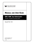
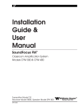
Installation
Guide &
User
Manual
PERSONAL PA System 400
Narrow-Band FM Wireless Listening System
Transmitter Model T17/*
Receiver Model R19/*, R19-4A, or R19-6
MAN 061B
®
Williams
Sound
Helping People Hear
PERSONAL PA SYSTEM 400
Installation Guide & User Manual
Contents
Page
System Overview
4
Narrow-Band Basics
5
System Controls and Features
6
System Set-Up and Operation
Antenna Connection
Power Connection
Audio Connection
Using a Microphone
Using R19/R19-4/R19-6 Receivers
Adjusting Receiver Tone Controls
Battery & Charger Information
7
Receiver Management Suggestions
10
Using a Remote Antenna
11
Troubleshooting Guide
12
Radio Interference / Tuning Instructions
14
Warranty
15
System Specifications
16
Williams
Sound ®
Helping People Hear
3
System Overview
Thank you for purchasing the Personal PA System
400 from Williams Sound Corporation. The PPA
System 400 is a Narrow-Band FM Listening System
which operates in the 72-76 MHz frequency band.
Designed for hearing assistance in places of public
access, the PERSONAL PA System 400 is for those
who need help overcoming background noise,
reverberation, or distance from the sound source.
The versatile PPA 400 is easily integrated with your
existing sound system or can be used with a
microphone as a stand-alone system.
To avoid difficulties, please read through these
instructions as you begin to use the system. Then
save the manual for questions that arise as you
continue to use your PERSONAL PA System 400.
If you have any problems with this Williams Sound
product, don’t hesitate to call us toll-free at
1-800-843-3544.
Your PPA System 400 has two principal parts: the
T17 Transmitter and the R19 Receivers. Much like a
miniature radio station, the transmitter and
microphone pick up the sounds you want to hear and
broadcast them over an FM radio signal. The
receivers are used to pick up the broadcast up to 500
feet away.
Figure 1: Overall System Diagram
Microphones
Sound System Amplifier
Loudspeakers
Line-Level Output
Line-Level Input
R19 / R19-4 / R19-6 Narrow-Band
Receivers w/Earphones
4
T17 Transmitter
Williams
Sound ®
Helping People Hear
Narrow-Band Basics
Less Interference
All FM receivers are tuned to a specific carrier
frequency. The selectivity of the receiver determines
how close nearby radio signals can be to this carrier
frequency before interference occurs. True narrowband receivers like the Williams Sound R19 use
dual-conversion circuitry to achieve a very narrow
“window” of acceptance for radio signals. This
allows them to operate in areas that have a lot of
different radio signals with less likelihood of
receiving interference.
More Simultaneous Channels
This narrow window of acceptance means more
channels can be squeezed into the designated
frequency band. Instead of dividing the Auditory
Assistance Band (72-76MHz) into 10 wide channels
(wide-band), the same band can be divided into 40
closely spaced (narrow-band) channels. The
selectivity of the R19 dual conversion receiver
allows you to operate on these closely-spaced
channels without interference from the next channel.
Greater Operating Range
Another measure of FM receiver performance is
sensitivity, measured by the weakest radio signal that
the receiver can respond to and still operate properly.
All hearing assistance transmitters are limited by
FCC Rules to the same transmitted signal strength,
so you can’t boost transmitter power or antenna
efficiency to get more operating distance. The
farther you move from the transmitting antenna, the
weaker the signal becomes. A very sensitive receiver
like the R19 will allow greater operating distance.
Because of its excellent operating distance, the
PPA System 400 can be used in situations where
maximum coverage area is needed.
Manufacturers often list a minimum signal strength
needed to maintain an acceptable noise level in the
receiver before it “squelches” or goes quiet. The
Williams Sound R19 receiver is designed to offer
maximum sensitivity with minimum noise and a
reasonable squelch action.
Overload Protection
Making a receiver sensitive for greater reception
range of weak signals can create a problem when the
receiver is used in an area that has strong radio
signals. Unless the receiver has an superior dynamic
range, it can be overloaded by the strong signal
and become noisy, distorted, or vulnerable to
interference. The Williams Sound R19 receiver uses
state-of-the-art circuitry for improved RF dynamic
range.
Capture Effect
When an FM receiver is presented with two radio
signals on the same channel, it will “lock on” to
whichever signal is stronger. This is called the
“capture effect.” Because signal strength is related
to distance, this usually means that the closest
transmitter antenna will produce the strongest signal
and “capture” the receiver.
Sound Quality
Narrow-band systems give up some frequency
response (extended highs and lows) and noise
performance compared to wide-band systems.
This is usually not a drawback for spoken word
presentations, but may not be optimal for programs
which are primarily music.
Williams
Sound ®
Helping People Hear
5
System Controls and Features
Figure 2: R19 Receiver Controls
Tone Control
EAR Jack
Volume/On-Off Control
Three-position switch which cuts low
frequencies at certain thresholds:
(Lo: 20 Hz, Mid: 120 Hz, Hi: 700 Hz)
Mono 3.5 mm mini earphone jack
EAR
Combination volume and on-off
rotary control.
Volume Channel
Lo Mid Hi
1
2
2
Tone
Off/On Indicator Light
Red LED which indicates
receiver is “on” when lit.
Off
Max
Channel Slide Switch
2-position slide switch used to
alternate between two pre-set
narrow-band frequencies.
Standard channels are 33 and
53. See page 14 for instruction
on changing system
frequencies.
Figure 3a: T17 Transmitter Front Panel Controls
Audio Indicator Light
Level Control
Flashes when audio signal is
present.
Screwdriver-adjust control used to
set the microphone input level or the
audio input level.
Williams Sound
Auditory Assistance Transmitter
Mic Input
Mic
Level
3.5 mm mini phone jack for use
with Williams Sound condenser
microphones. Supplies +DC power
for condenser microphones.
-
Audio On
+
ON Indicator Light
Glows when power is applied to
the transmitter. There is no
on/off switch. The T17 is
designed to be left on
continuously.
Figure 3b: T17 Transmitter Rear Panel Features
Antenna Mounting Stud
Power Input Jack
(Top Panel)
For use with the “rubber duckie”
type antenna supplied.
Connects to the plug on the wall
transformer power supply.
Antenna Output
Connector
This connector is defeated, as
specified by FCC Rules. To use
the ANT 005 remote antenna,
contact your dealer or Williams
Sound. See installation
procedures on page 11.
6
FM Transmitter Model PPA T17
Williams Sound Corp., Minneapolis, MN, USA
Antenna
Power
12 VAC
100 mA
75 Ohm
Audio In
Hi-Z
Line
Audio Input
An RCA-type jack for
connecting the transmitter to
other sound systems.
Accepts line-level,
unbalanced audio inputs.
Made in U.S.A
Williams
Sound ®
Helping People Hear
System Set-Up & Operation
T17 Transmitter
Step 1:
buzz in the sound system, see the
Troubleshooting section on page 12.
Install the antenna.
The “rubber duckie” whip antenna fits into
the hole on top of the transmitter and
threads onto a mounting stud inside.
Guide the antenna onto the stud and turn it
clockwise to tighten. Do not use excessive
force to tighten the antenna. It only needs
to be “finger-tight.”
Step 3:
Step 3a: (If you will be using the T17 with its own
microphone as a stand-alone system)
Any Williams Sound microphone with a
3.5 mm mini phone plug can be used with
the T17. Plug the microphone into the
“Mic” jack on the front panel of the T17.
If the optional remote antenna (ANT 005)
is most appropriate for your situation,
contact your dealer or Williams Sound
Corp. The remote antenna installation is
detailed on page 11.
Step 2:
The T17 is designed to supply positive
DC voltage to the plug tip of 2-wire,
“barefoot” electret (power condenser)
microphones. If you will be using the
T17 with a non-Williams Sound, Lo-Z
(dynamic) microphone, this DC power
should be turned off. (See Figure 4.)
Connect the transmitter to power.
The T17 is supplied with a wall
transformer power supply. Plug the
transformer into a 120 Volt, 60 Hz wall
outlet. Then plug the power cord into the
“Power” connector on the rear panel of the
T17. The green indicator light on the front
panel of the T17 should glow when the
power is connected.
Make audio connections.
If you use both the Microphone input and
the Audio Input on the T17, the signals
will be mixed together.
Step 3b: (If you will be using the T17 with an
existing sound system)
There is no on/off switch. The T17 is
designed to be continuously on. The wall
transformer can be plugged into a
switched outlet that turns on when the
other sound equipment is turned on. If
turning the T17 on creates a hum or
Refer to the Overall System Diagram on
page 4. Use the audio cable supplied to
connect the T17 “Audio In” jack to an
appropriate audio output jack on the sound
system mixer or amplifier. The T17 is
designed to work with an unbalanced, linelevel audio signal.
Figure 4: Turning Off DC Microphone Power
Step 1:
Unplug the power cord from the T17 and remove its
antenna.
Step 2:
Use a phillips-type screwdriver to loosen the two
screws on the rear of the transmitter. Remove the
cover. Slide the circuit board out of the case.
Step 3:
Use the diagram to locate the HD4 Jumper. This
black jumper is also labeled on the T17 circuit
board.
Step 4:
Pull the HD4 Jumper off the two pins it connects.
DO NOT MAKE ANY OTHER ADJUSTMENTS! For
handy storage, simply turn the jumper sideways
and place it on just one of the two pins.
Step 5:
Front
HD4 Jumper
Re-assemble the transmitter.
Williams
Sound ®
Helping People Hear
7
Suitable connections are:
Step 5:
The T17 Transmitter has a screwdriveradjust input level control located on the
front panel to compensate for different
input signal levels. The yellow audio
indicator light should flash with the signal.
If the sound through the receiver is clear
and loud and the audio indicator light
flashes with the signal, no adjustment is
needed. If the sound through the receiver
is weak and the audio indicator light does
not flash even with the volume control
turned all the way up, turn the T17 input
level control clockwise to increase the
signal. If noise (room noise or electronic
noise) seems to grow after talking stops,
the input level control should be turned
counter-clockwise to decrease the signal.
Step 6:
If you don’t hear the signal in the receiver,
try moving the R19 channel selector
switch to the other channel. The R19-4
features a four-channel selector knob
preset to channels 13, 23, 33, and 53.
R19-6 features a six-channel selector knob
preset to channels 13, 23, 33, 53, 38, and
43. Turn the selector knob until you hear
the desired program.
Choice 1: TAPE OUT or LINE OUT Jack
Choice 2: BOOSTER or BRIDGING Jack
Choice 3: Speaker Terminal, 8 Ohm Tap
If your amplifier or mixer does not have
RCA-type connectors, you can obtain
adapters from your Williams Sound
Authorized Dealer or a local radio parts
store. If the TAPE OUT jack is already in
use, a Y-Cord can be used to connect the
T17 and a second device to the same jack.
Step 4:
Use a receiver to test the system and set
the input level control. The steps in the
next section explain receiver operation.
R19 / R19-4 / R19-6 Receivers
Step 1:
Install the batteries.
Pry open the battery compartment door
with a coin. Press the batteries into place,
observing proper battery polarity. Do not
force the batteries in backwards!
Step 2:
Plug the earphone or headphone into the
earphone jack.
Step 3:
Turn the receiver on by turning the
volume control clockwise. Turning the
knob clockwise will increase the volume.
Turning the knob counter-clockwise will
decrease the volume. To avoid draining
the battery, make sure the receiver is
turned off when not in use.
Step 4:
If you are using the PPA System 400 with
an existing sound system, make sure the
sound system is turned on. Have someone
speak into a microphone while you listen
with the receiver and earphone. You
should be able to hear their voice through
the receiver.
If you are using the PPA System 400 with
its own microphone, have someone speak
into the microphone while you listen with
the receiver and earphone. You should be
able to hear their voice through the
receiver.
8
Adjusting The Receiver Tone Controls
The R19, R19-4, and R19-6 allow adjustments to cut
low frequency sounds. Use the three-position slide
switch on the receiver control panel to make this
adjustment.
Battery & Charger Information
Alkaline Batteries
In normal use, two BAT 001 heavy-duty, AA
alkaline batteries will last 90-100 hours. If the sound
becomes weak or distorted, replace the battery. Do
not leave dead batteries in the receivers.
Rechargeable Batteries
The receivers can also use a rechargeable batteries.
We recommend only the BAT 026 AA Ni-Cad
battery. These batteries will last about 45-50 hrs per
charge. Batteries from other suppliers may provide
shorter operating life.
Williams
Sound ®
Helping People Hear
Figure 5: Using The Optional CHG 200A Battery Charger
Step 1:
Plug the CHG 200’s power supply into
the Power Jack on the back of the unit
and a standard AC wall outlet.
Step 2:
Wrap the power cord around the Cord
Hook (See figure at right.) This will
minimize strain on the cord and jack and
insure that the power cord is not detached
during charging.
Step 3:
Make sure the receivers to be charged are
turned OFF.
Step 4:
Place the receivers in the slots so that the
CHG 200’s Charging Pins and receiver’s
side panel contacts are coupled. Make
sure that the charging contact holes line
up with the charging pins. The receivers
should drop easily into the slots. DO
NOT FORCE THEM IN BACKWARDS.
Step 5:
Charging
Contact Holes
Charging
Indicators
Charging
Pins
The Charging Indicators will light,
indicating that charging is in process.
It takes about 14 hours to fully charge
the batteries. Remove the receivers
when charging is completed.
Further Suggestions
Receivers SHOULD NOT be left charging
continuously when not in use. Receivers should
always be turned OFF while charging.
Cord Hook
Power Input
It’s best to allow the batteries to fully discharge
before charging.
If the batteries are near end of life and the LED
turns off while the receiver is operating, this is an
indication to change or recharge your batteries.
Approximately one hour of battery life remains.
Repeatedly charging the batteries after short periods
of use (1-2 hours) will shorten battery life.
Rechargeable batteries will need to be replaced
after 1–2 years of use.
Williams
Sound ®
Helping People Hear
!! WARNING !!
DO NOT ATTEMPT TO RECHARGE
DISPOSABLE BATTERIES!
The batteries may heat up and burst, causing
possible injury and damage to the equipment.
Avoid shorting the plus and minus battery
terminals together with metal objects. Battery
damage and burns can result!
Use only Williams Sound supplied chargers and
batteries!
9
Suggestions For Receiver Management
Different types of facilities will use different
approaches for receiver management and earphone
sanitation. Below are some options that customers
have used successfully.
1.
Regular users purchase their own receiver and
take care of their own batteries and earphone.
2.
Some facilities label the receiver and earphone
with the names of regular users so each person
uses the same receiver and earphone.
3.
Ushers issue receivers to people who request
them. Earphones are sanitized after use. Foam
ear cushions can be replaced or washed with a
mild detergent, rinsed thoroughly and air
dried. The EAR 022 Surround Earphone can
be sanitized with an alcohol pad.
4.
The receivers can be stored in a multiple
compartment storage case with a credit card or
driver's license left as collateral for the
receiver.
5.
Regular users purchase their own earphone or
headphone and bring them to use with
receivers at the facility.
10
Williams
Sound ®
Helping People Hear
Using A Remote Antenna
The optional ANT 005 Coaxial Antenna is intended
for use with rack-mounted transmitters or in
installation areas where a remote antenna is needed
for maximum operating distance.
Per FCC Rules, only antennas supplied by Williams
Sound may be used with this transmitter.
Do not cut or alter the antenna cable before
reading the instructions below!
The ANT 005 Coaxial Antenna is a length of coaxial
cable with an “F” connector on one end and an
80-inch antenna built onto the other end. The last 80
inches of the antenna make up the active element,
which is covered by nylon braid. The active
element should never be altered. The remainder of
the antenna cable is RG-59 coax feedline. The
feedline can be shortened if you have the tools to
install a new F-connector. If you need a longer
feedline, extension cables are available from
Williams Sound in 50 foot lengths (WCA 008 50).
Never splice coax cables together. Always use
proper connectors.
Installing The Remote Antenna
Step 1:
Remove the “rubber duckie” antenna from
the T17’s top panel by turning it
COUNTER-CLOCKWISE.
Step 2:
Use a pliers to remove the cap on the
antenna connector. Be sure to turn
COUNTER-CLOCKWISE to remove the
cap.
Step 3:
The ANT 005 Coaxial Antenna connects
to the “Antenna” connector on the rear
panel of the T17 Transmitter. Attach the
cable, making sure the center wire on the
cable enters the hole in the center of the
receptacle. The connectors screw together
and need only be “finger-tight.”
Williams
Sound ®
Helping People Hear
Remote Antenna Location Guidelines
For maximum signal strength, it is best to select an
antenna location somewhere within the listening
area. The preferred location is towards the front of
the listening area and above the seats. The active
element (nylon braid covered portion) should be
kept straight, not coiled, and must be vertical.
Radio signals will generally pass through non-metal
structures. The antenna can be mounted on a wall, in
a corner, or behind a wooden beam. It may also be
hung vertically from the ceiling, with a small weight
attached to the end to make it hang freely. If you
need to run the feedline through a wall, a 1/2" hole is
necessary to pass the connector through.
Avoid placing the antenna within four feet of steel
beams or near structural steel elements. Metal
studs, ductwork, and foil-backed insulation can
absorb radio energy, greatly reducing the range
of the system. DO NOT put the active element
(last 80 inches) inside a metal conduit. The
feedline is categorized as Class II wiring. Thus, it
may be (but is not required to be) routed through
metal conduit, but NOT with microphone cables
or AC power wiring.
Nylon clamps and screws are provided to attach the
Coax Antenna to a wall. Locate the clamps every 3 4 feet. DO NOT bend the cable sharply at any point.
Allow at least a 3" radius for turns. DO NOT staple
the cable in place. Use the cable clamps provided or
hang the antenna from the excess nylon braid at the
end of the antenna element.
11
Troubleshooting Guide
Transmitter “Power” light not on.
1.
Make sure the wall transformer is plugged into
the transmitter.
Sound through receivers is loud, but distorted.
Noise (room noise or electronic noise) seems to
grow after talking stops. Audio Indicator Light is
continuously on.
2.
Make sure the electrical outlet is on.
1.
No sound through receivers.
1.
Try switching to the other channel on the R19.
2.
If some of the receivers work, but others don't,
check for bad batteries or earphones on the
receivers that aren't working. Check to see that
those receivers’ frequencies match the
transmitter’s frequency. The R19 is preset for
channels 33 and 53.
3.
If none of the receivers work, check to see if
the power is connected to the transmitter and
the “Power” light is on. Check to see if the
transmitter and receivers are set on the same
frequency. The frequency sticker is on the
bottom of the transmitter and inside the back
cover of the receiver. If they don’t match, see
the Tuning Instructions on page 14.
4.
Check to see if the transmitter is connected
properly to the sound system. See page 7.
5.
Turn the screwdriver-adjust input level control
located on the T17 front panel clockwise to
increase the input signal strength. Check to see
that the audio light is flashing occasionally but
not continuously.
6.
If you are not using an input signal from a
sound system, make sure the Williams Sound
microphone is plugged into the “Mic” jack on
the front of the T17 transmitter.
7.
Make sure the antenna is installed and
connected properly. See pages 7 and 11.
12
Turn the screwdriver-adjust input level control
located on the T17 front panel counterclockwise to decrease the input signal
strength. The audio indicator light should
flash, not be lit continuously.
Sound through the receivers is weak and noisy.
Audio Indicator Light is not lit.
1.
Turn the screwdriver-adjust input level control
located on the T17 front panel clockwise to
increase the input signal strength. The audio
indicator light should be flashing
2.
Increase the input signal level from the sound
system.
Buzzing or humming noise in sound system.
1.
Most likely, there is nothing wrong with the
T17 Transmitter. One or more pieces of
equipment in the sound system are being
disturbed by RF (Radio Frequency) signals
produced by the T17. The most likely suspects
are your amplifier, mixer, or tape deck. The
RF gets into the other equipment primarily
through the power cord, speaker wires, or
unshielded inputs, all of which can act as
antennas. Try moving the transmitter away
from the other sound equipment.
2.
If remedy one does not solve the problem, we
recommend using the optional Coax Antenna
(ANT 005), which should be located 15-20
feet away from the other sound equipment.
You may add additional RG-59 feedline as
needed.
Williams
Sound ®
Helping People Hear
3.
If changing to the Coax Antenna doesn’t help,
it’s time to dig deeper into the problem.
This involves a slight modification to the
equipment causing the problem. Unless you
have the necessary technical skills, this is best
left to a qualified electronics repair technician.
Call your Authorized Dealer or Williams
Sound for more information. Ask for the Buzz
Paper.
Williams
Sound ®
Helping People Hear
13
Radio Interference / Tuning Instructions
The PERSONAL PA System 400 is usually not
disturbed by other radio services. However, there are
no exclusive channels for this radio service. If you
experience interference, follow the directions below.
Frequency Change Instructions
Step 1:
Unplug the power cord from the
transmitter and remove the antenna.
Step 2:
Use a phillips-type screwdriver to loosen
the two screws on the rear of the
transmitter. Remove the cover. Slide the
circuit board out of the case.
Step 3:
Use the diagram in Figure 6 to locate the
frequency selector switches on the circuit
board. You will also find the Switch
Settings Table in Figure 6.
Step 4:
Use a paper clip or small screwdriver (not
a pencil point) to move the switches to
correspond with the switch positions for
channel 53 on the programming chart.
DO NOT TOUCH ANY OF THE OTHER
ADJUSTMENTS!
Step 5:
Re-assemble the transmitter and plug it in.
Connect a tape player or radio to the
transmitter to provide a tuning signal for
the receivers.
Step 6:
Change all receiver frequencies to receiver
channel 53. For the R19, move the slide
switch on the control panel to channel 2
Receiver Frequencies
The R19, R19-4, and R19-6 operate on fixed
crystals. Because of the nature of these crystals,
frequency tuning is highly stable over the life of the
receiver.
Crystals are not tunable. if alternate frequencies
are needed, return the receivers to your dealer for
new crystals. There are 10 standard frequencies
available.
The R19 has a slide switch to select from channels 1
or 2 (channels 33 and 53).
The R19-4’s rotary switch allows you to select
between channels 1-4, (channels 13, 23, 33, and 53).
The R19-6’s rotary switch allows you to select
between channels 1-6, (channels 13, 23, 33, 53, 38,
and 43).
For the R19-4 and R19-6, turn the rotary
switch on the control panel to channel 4.
Step 7:
Listen for the signal through the receivers.
Step 8:
If you are using R19 Receivers and are
still experiencing interference, you must
return the receivers to your dealer for the
installation of new crystals.
If you are using R19-4 or R19-6
Receivers, repeat the steps above for
channels 13 or 23.
14
Williams
Sound ®
Helping People Hear
Warranty
The Williams Sound T17 Transmitter and R19/
R19-4/R19-6 Receivers are warranted against
defects in workmanship and materials for FIVE
YEARS.
Fig. 6: Frequency Change Diagrams
Frequency Selector Switches
Microphones, earphones, cables, carry cases,
rechargeable batteries and chargers are warranted
against defects in workmanship and materials for 90
DAYS.
Front
This warranty does not extend to intentional or
accidental physical damage.
Location of T17 Selector Switches
This warranty applies only to products returned to
Williams Sound for service. To return a product for
service, call 1-800-843-3544 and request a Return
Authorization (RA) number.
OFF
ON
1 2 3 4 5 6 7 8
Switches set for 72.9 MHz
T17 Selector Switches
CH
NO.
FREQ
(MHz)
1
2
Switch Settings
3
4
5
6
7
8
CH 13 72.100 DN
UP
DN
UP
DN DN
DN DN
CH 18 72.300 DN
UP
DN
UP
UP
DN
DN DN
CH 23 72.500 DN
UP
DN
UP
DN DN
UP DN
CH 28 72.700 DN
UP
DN
UP
UP
DN
UP DN
CH 33 72.900 DN
UP
DN
UP
DN DN
DN UP
CH 38 74.700 UP
DN
DN
UP
UP
DN
DN UP
CH 43 75.300 UP
UP
DN
UP
DN DN
DN DN
CH 48 75.500 UP
UP
DN
UP
UP
DN
DN DN
CH 53 75.700 UP
UP
DN
UP
DN DN
UP DN
CH 58 75.900 UP
UP
DN
UP
UP
UP DN
DN
T17 Switch Settings Table
Williams
Sound ®
Helping People Hear
15
PERSONAL PA SYSTEM 400 SPECIFICATIONS
PERSONAL PA Transmitter Model T17/*
Dimensions & Weight:
3.25" W x 6.875" L x 1.75" H (82.5mm x
174.6mm x 44.5mm); 13 oz., 368.5 g
Color:
Black
Power (U.S./Canada): 105-130 VAC, 50-60Hz, .5W
Operating Frequencies: CH 13 (72.100 MHz), CH 18 (72.300MHz),
CH 23 (72.500MHz), CH 28 (72.700MHz),
CH 33 (72.900MHz), CH 38 (74.700MHz)
CH 43 (75.300 MHz), CH 48 (75.500MHz),
CH 53 (75.700MHz), CH 58 (75.900MHz),
CH 33 (72.900MHz) is standard
Frequency Selector:
Internal switches, 10 channels
RF Field Strength:
8000 µV/m at 30 m Max., 20mW typical
Nominal Range:
300–500 feet, 90–150m
Modulation:
5 kHz (narrow–band)
Stability:
± .005% over 0-50˚C
FCC ID:
CNMT17
*NOTE:
Pre-Emphasis:
Frequency Response:
Distortion:
Signal to Noise Ratio:
Microphone Input:
Mic Input Level:
Line-Level Input:
Line Input Level:
Input Attenuator:
Antenna Outputs:
300 µS
100 Hz - 5 kHz ±3dB
1 % Max. THD
50–55 dB with R19 Receiver
3.5mm mini phone jack, supplies +DC
for electret mics
1 - 10 mV, nominal
RCA Jack, Hi Z, unbal.
.1 - 1 Vrms, nominal
Pot, screwdriver-adjust
Thread Mount for "rubber duckie" flexible
whip antenna, optional hard-wired 75Ω
Coaxial Antenna (ANT 005) uses RG-59
cable, 400ft. (140m) max. cable length
The T17 Transmitter is field-tunable to any of 10 narrow-band channels. Specific transmitter model names
contain a frequency code. For example, Model T17/33 is preset to channel 33.
PERSONAL PA Receivers: Model R19/*, Model R19-4A, Model R19-6
Model PPA R19:
Model PPA R19–4:
Model PPA R19–6:
Dimensions:
Weight:
Color:
Battery Type:
Battery Drain:
Battery Life:
Operating Freq:
Intermediate Freqs:
*NOTE:
2-Channel, Pre-Tuned, Selectable
CH 33 (72.9 MHz), CH 53 (75.7 MHz)
standard
10 Channels Available (72.1-75.9 MHz)
4-Channel, Pre-Tuned, Selectable
CH 13 (72.1 MHz), CH 23 (72.5 MHz),
CH 33 (72.9 MHz), CH 53 (75.7 MHz)
6-Channel, Pre-Tuned, Selectable
CH 13 (72.1 MHz), CH 23 (72.5 MHz),
CH 33 (72.9 MHz), CH 53 (75.7 MHz)
CH 38 (74.7 MHz), CH 43 (75.3 MHz)
3-5/8" L x 2-3/8" W x 7/8" H
(92.1 mm x 60.3 mm x 22.2 mm)
3.2 oz (90 g) with battery
Neptune Blue
(2) BAT 001 AA Alkaline
or (2) BAT 026 Ni-Cad
20 mA, nominal
90–100 hrs with 2 AA Alkaline
45-50 hrs/charge with BAT 026
Crystal controlled. See factory for
frequency changing instructions.
10.7 MHz, 455 kHz
FCC ID:
Earphone:
Output Connector:
FM Deviation:
De-Emphasis:
Sensitivity:
Squelch Level:
Frequency Response:
Receiver Antenna:
Signal-to-Noise Ratio:
Audio Output:
Acoustic Output:
CONTROLS
Tone:
Volume & On/Off:
Channel Selector:
CNMR19
Earbud-type with foam cushion,
3.5 mm plug, 32 Ω
3.5 mm mono mini phone jack
Narrow–band, 5 kHz
300 µS
0.7 µV at 12 dB Sinad
4 µV for minimum 40 dB S/N ratio
100 – 5 kHz, ± 3 dB (Tone: Lo)
Integral with earphone cord
50dB
35 mW, max. at 16 Ω
(Tone: Lo; 3 VDC Bat.)
125 dB Max SSPL90 with EAR 013
Switched Low-Cut
Lo: 20 Hz / Mid: 120 Hz / Hi: 700 Hz
Combination, integral
PPA R19: 2-position, slide switch
PPA R19-4: 4-position, rotary switch
PPA R19-6: 6-position, rotary switch
Specific receiver model numbers contain a frequency code. For example, Model R19/33/53 is preset to
channels 33 and 53. The R19 and R19-4 Receivers are crystal-controlled for optimal stability. If the standard
R19 or R19-4 channels cannot be used, the receiver must be returned to the factory for alternate crystals.
Williams Sound Corp.
10399 West 70th St., Eden Prairie, MN 55344-3459
U.S.A. 800-328-6190 / 612-943-2252 / FAX: 612-943-2174
© 1996, Williams Sound Corp.
MAN 061B