1
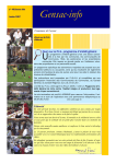
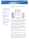
AALogic D-105 USER MANUAL VERSION 1.0.4 Allied Analogic, Inc. 132 Redtail Ct. Weatherford, TX 76088 (817) 599-0272 www.aalogic.com Copyright 2015, All rights reserved ii D -105 User Manual 1.0.4 TABLE OF CONTENTS 1 Introduction ............................................................................................................................. 1 2 D-105 Power ........................................................................................................................... 1 3 Front Cover ............................................................................................................................. 1 4 Cautions .................................................................................................................................. 2 4.1 Ground Connection....................................................................................................... 2 4.2 Water Damage .............................................................................................................. 2 4.3 Noise and Leakage Measurements ............................................................................... 2 5 Front Panel .............................................................................................................................. 3 6 Cord Connections.................................................................................................................... 4 7 Configuration – CFG .............................................................................................................. 4 7.1 VOP – CFG-F1 ............................................................................................................. 4 7.2 TM OUT – F2 ............................................................................................................... 5 7.3 SYS – F3 – Display and Volume.................................................................................. 5 7.3.1 BCKLTE – Backlight ............................................................................................... 5 7.3.2 CONTRST – Contrast ............................................................................................... 5 7.3.3 VOLUME ................................................................................................................. 6 8 Reading Meter Measurements ................................................................................................ 6 9 DC Voltage Measurement – Working Pairs or Foreign Battery ............................................. 7 10 OHMS Measurement – Grounds and Shorts .......................................................................... 7 11 Capacitance Measurements – Pair Length, Balance, and Faults ............................................ 8 12 TEST ....................................................................................................................................... 8 12.1 OPN MTR – Pair Fault Detection ......................................................................... 9 12.2 Noise...................................................................................................................... 9 12.3 Leakage ............................................................................................................... 10 D -105 User Manual 1.0.4 i 13 SCAN .................................................................................................................................... 10 13.1 Loads ................................................................................................................... 10 13.2 BALANCE .......................................................................................................... 11 13.3 FREQ – Frequency Detection ............................................................................. 11 14 AUTO TEST ......................................................................................................................... 12 15 SPL FUNC – Special Functions ........................................................................................... 12 16 15.1 TDR – Time Domain Reflectometer ................................................................... 12 15.2 CKT ID – Circuit ID ........................................................................................... 13 15.3 LISTEN ............................................................................................................... 14 15.3.1 MONITOR....................................................................................................... 14 15.3.2 PROBE ............................................................................................................ 14 TONE .................................................................................................................................... 15 16.1 F1 – SPLX ........................................................................................................... 15 16.2 F2 – TRIPLEX .................................................................................................... 15 16.3 T/R/MET – TG, RG, and TR (Metallic) ............................................................. 15 16.4 Using Tone .......................................................................................................... 15 16.5 Confirming Pair Identification ............................................................................ 16 16.6 Confirming Pairs With Impairments ................................................................... 16 17 Talk Battery .......................................................................................................................... 16 18 Warranty ............................................................................................................................... 17 19 Specifications ........................................................................................................................ 18 ii D -105 User Manual 1.0.4 1 INTRODUCTION The AALogic D-105 digital test set offers features for Cable Transfers, Restoration, Troubleshooting and a variety of tests to help qualify pairs for DSL provisioning. The D-105 main features include: TDR, Step or Pulse “Z Stress” DSL Balance Leakage Tests Automatic Digital Metering Automated Fault Testing 2 Tone Generator Special Circuit ID Frequency Scanning Load Coil Detection Expanded Talk Battery Support D-105 POWER The D-105 uses an internal, rechargeable lithium ion battery. This eliminates the need to replace batteries. The D-105 can be operated indefinitely if connected to an AC power source using the included power supply. NOTE: The D-105 should not be used for leakage or noise measurements while the power supply is connected. The D-105 should be charged at least three hours prior to use on battery power for maximum operating time. A battery charge indicator is displayed at the top left of all displays. The D-105 should be charged soon when only one segment is displayed. A green light is visible at the TALK connector on the bottom panel when the power supply is connected to the D-105 and a suitable AC power source. A red light is visible while the D-105 is charging. The red light will turn off when charging is complete. NOTE: Recommended Ambient Charge Temperature 0-45 C (32-112 F) 3 FRONT COVER The front cover of the D-105 can be removed for convenience. Retract the two spring-loaded pins holding the lid to the case and remove the lid. D -105 User Manual 1.0.4 1 4 4.1 CAUTIONS GROUND CONNECTION For all tests and measurements, a good cable ground is required. The D-105 has a ground cable permanently attached. The clip is a battery style clip with a green boot. Position the D-105 in a location that allows the clip to attach firmly to the cable or frame ground as appropriate. The ground can be extended by using several cable pairs tied to a good ground. This should be considered only if the D-105 cannot be connected directly to the ground. A GROUND STRAP, CABLE SHEATH, OR GROUND BAR MAY NOT BE PROPERLY CONNECTED TO GROUND THE FIRST TROUBLE SHOOTING STEP SHOULD ALWAYS BE CONFIRMING THAT THE TEST SET HAS A GOOD GROUND CONNECTION. 4.2 WATER DAMAGE The D-105 case is not water proof and may be damaged if left in the rain or submerged in water. 4.3 NOISE AND LEAKAGE MEASUREMENTS The D-105 should not be connected to the AC charger when Noise or Leakage measurements are being made. The AC power noise can introduce errors into these measurements. THE NOISE AND LEAKAGE TEST OPTIONS WILL BE HIDDEN WHEN THE TEST KEY IS PRESSED AND THE POWER SUPPLY IS CONNECTED. 4.4 CHARGE TEMPERATURE The D-105 uses an internal high energy Li-ion battery. Although the system can operate in a wide range of temperatures; to obtain full battery life the unit should only be charged when ambient temperatures are between 0-45 degrees C (32-112F). 2 D -105 User Manual 1.0.4 5 FRONT PANEL The front panel of the D-105 provides easy access to the test and measurement features. The digital display provides prompts and measurement data. The display is backlight and contrast adjustable to make it easy to read in a variety of lighting conditions. Key PWR/CLR TEST SCAN AUTO TEST CFG SPL FUNC TONE TALK F1,F2,F3 Function Turns the power on and off and exiting menus and tests. Selects the open meter, noise, or leakage tests. Selects the loads, balance, or frequency scans. Selects the automatic test Allows setting the VOP (TDR), change the timeout (TM OUT), adjust the display and volume (SYS). Selects the TDR, Circuit ID, or Monitor Selects on of the tone modes: SIMPLEX, TRIPLEX, or Tip/Ring/Metallic. Turns the talk battery feature ON and OFF (requires the talk cord). Function keys change. The function is shown on the display above the keys. D -105 User Manual 1.0.4 3 6 CORD CONNECTIONS 1 2 3 4 5 The bottom panel of the D-105 has the connections for the cords and the speaker output grid. The cords are connected according to the labels on the front panel. The cords are identified in the following table. Item Number 1 2 3 4 5 Function Pair Test cord - Used for all test connections to cable pairs. Ground cord - Connected to cable ground for all tests and measurements. Speaker Outlet - Keep this area clear for the best volume. Talk Cord - Only required when using the internal talk battery feature. Power supply - Used to charge the internal battery and operate the unit for long periods. CONFIGURATION – CFG 7 Some configuration options are available on the D -105. These options either adjust measurements or operating features of the D -105. To access the configurable options, press the CFG key from any screen. The configurable options are described below. Configuration settings are stored in the D-105 memory and it is not necessary to reset them each time the D-105 is turned on. 7.1 VOP – CFG-F1 The VOP configuration option allows the user to set the velocity of propagation (VOP) for the time domain reflectometer (TDR). This is necessary to allow the TDR to determine the distance to the fault. 4 From any screen, press CFG key – F1 VOP. Use the F1 and F3 keys to highlight the cable type and gauge. D -105 User Manual 1.0.4 Press F2 to SET the value. If a different VOP value is needed, select the CUSTOM option. o Highlight CUSTOM. o Press F2 SET. o Use the F1and F3 keys to change the VOP value. o Press F2 - SET The D-105 returns to the main screen. Note: For convenience, the VOP configuration can be accessed by pressing the CFG key while using the TDR function. Make and changes and press the F2 – SET to return to the TDR. 7.2 TM OUT – F2 The D-105 has a power off timeout option. This time out conserves battery power if the user does not press a key within the timeout period. The timeout can be adjusted or turned off completely. The default timeout is 30 minutes. 7.3 From any screen, press CFG key – F2 TM OUT. Use the F1 and F3 keys to select 15, 30, 45, or OFF. Values are in minutes. Press F2 to SET the value. The D-105 returns to the main screen. SYS – F3 – DISPLAY AND VOLUME The display backlight and contrast can be adjusted for the best visibility in all lighting and temperature conditions. The speaker volume can also be adjusted for noisy areas or when the sound would be undesirable. From any screen, press CFG key – F3 SYS. Press the keys and follow the steps below. 7.3.1 BCKLTE – BACKLIGHT Press F1 – BCKLTE Use the F1 and F3 keys to adjust the backlight level. The screen will adjust to the selected value. Adjust the backlight for the best view. Press F2 to SET the value. The D-105 returns to the main screen. 7.3.2 CONTRST – CONTRAST Press F2 – CONTRST D -105 User Manual 1.0.4 5 7.3.3 8 Use the F1 and F3 keys to adjust the screen contrast. The screen will adjust to the selected value. Adjust the contrast for the best view. Press F2 to SET the value. The D-105 returns to the main screen. VOLUME Press F3 – VOLUME Use the F1 and F3 keys to adjust the volume. A key beep indicates the current volume level. Adjust the setting for the desired volume. Press F2 to SET the value. The D-105 returns to the main screen. READING METER MEASUREMENTS The meter display is designed to show three measurements at the same time, TR, TG, and RG. Depending on the test or measurement mode selected, each reading may be voltage, resistance, or capacitive length. The picture below illustrates a typical meter display. In the image above, the Open Meter is displayed. 6 The TR measurement is 12.71KF. This reading indicates the length of the pair. There is a problem on the pair so the TR length may be incorrect. The TG measurement is 69Ω. The measurement is shown on a black background to indicate a problem. This is a resistance reading indicating a GROUND on the tip side of the pair. The RG reading is 9.91KF. This is length reading. This reading may also be affected by the ground fault on the TG. D -105 User Manual 1.0.4 9 A small square is displayed at the upper left corner of the measurement window each time a measurement is updated (see the TR window in the image). Wait until this square is displayed for a window before taking a reading any time the cable clips are moved or a change in the pair is made. It may take up to 6 seconds for all the measurements to be updated depending on the condition of the pair. DC VOLTAGE MEASUREMENT – WORKING PAIRS OR FOREIGN BATTERY The D-105 measures DC voltage Tip to Ring, Ring to Ground, and Tip to Ground and displays the results on one screen. The measurements are continuous allowing observation of changes in the pair voltage over time. Connect the green ground clip to the best ground available. Connect the red pair test cord to the D -105. Connect the test clips to the pair to be tested. From the main screen, press F1 key – VOLTS. (Press CLR key, if necessary, to return to the main screen.) Read the TR, TG and RG measurements in VOLTS. Press CLR or other function button to exit the VOLTS function. 10 OHMS MEASUREMENT – GROUNDS AND SHORTS The D-105 measures OHMs resistance Tip to Ring, Ring to Ground, and Tip to Ground and displays the results on one screen. The measurements are continuous allowing observation of changes in the pair resistance over time. This also allows the user to see when a ground or short is cleared. The OHMS function reads grounds and shorts up to 1 MΩ. For resistances greater than 1MΩ use the leakage TEST. Connect the green ground clip to the best ground available. Connect the red pair test cord to the D -105. Connect the test clips to the pair to be tested. From the main screen, press F2 key – OHMS. (Press CLR key, if necessary, to return to the main screen.) Read the TR, TG and RG measurements in OHMS. This function will also show voltage TR/TG/RG, if ± 2.5 VDC or more is present on the pair, with a black background. It is not necessary to use the VOLTS feature before using the OHMS feature. TR measurements indicate a SHORT. TG or RG measurements indicate a GROUND. o 100 Ω D -105 User Manual 1.0.4 = 100 OHMS 7 o 1.00 KΩ = 1,000 OHMS o > 1 MΩ = greater than 1,000,000 OHMS Press CLR or other function button to exit the OHMS function. 11 CAPACITANCE MEASUREMENTS – PAIR LENGTH, BALANCE, AND FAULTS The D-105 measures capacitance Tip to Ring, Ring to Ground, and Tip to Ground and displays the results on one screen. The measurements are continuous allowing observation of changes in the pair capacitance over time. The CAPMTR shows capacitive pair length in KF, 1000’s of feet. The pair length is indicated Tip to Ring. The Ring to Ground and Tip to Ground measurements are used to indicate an unbalanced pair. This may be due to an open splice or bridge tap on one side of the pair. The CAPMTR function reads distance up to 100KF. Connect the green ground clip to the best ground available. Connect the red pair test cord to the D -105. Connect the test clips to the pair to be tested. From the main screen, press F3 key – CAPMTR. (Press CLR key, if necessary, to return to the main screen.) Read the TR, TG and RG measurements in DISTANCE - KF. This function will also show voltage or resistance TR, TG and RG if present on the pair, with a black background. The voltage is displayed if it is greater than ± 2.5 VDC. Resistance is displayed if it is less than 100KΩ. It is not necessary to use the VOLTS or OHMS features before using the CAPMTR feature. TR measurements indicate the distance of the pair, including bridge tap if present. TG or RG measurements should be close to each other if the pair is balanced. Large differences between the TG and RG indicate an unbalanced condition. Press CLR or other function button to exit the CAPMTR function. 12 TEST The TEST functions allow the user to look at typical DC faults on a pair, measure metallic and power influence noise, and check for leakage. These diagnostic tests rapidly identify a majority of the typical pair faults. From any screen, press the TEST key 8 D -105 User Manual 1.0.4 12.1 OPN MTR – PAIR FAULT DETECTION The OPN MTR test function examines the pair for DC voltage, resistance faults, and capacitive condition of the pair on a single, continuously updated screen. The test automatically checks for voltage then resistance and finally capacitance between the TR, TG, and RG. The following conditions may be detected: Working Battery On Pairs Special Circuits (applied voltage) Shorts Grounds Vacant Pair Length Capacitive Balance (TG is longer or shorter than RG) Connect the green ground clip to the best ground available. Connect the red pair test cord to the D -105. Connect the test clips to the pair to be tested. From any screen, press TEST key – F1 OPN MTR. Allow the screen to update the TR. TG, and RG readings. Read the displayed conditions. The meter continues to update the readings. Any changes in the pair will be displayed the next time the reading is updated. All readings are updated each 5 seconds or less. Poor Grounding (TG and RG capacitance varies from the TR capacitance) Bridge Tap or Drop Wires (pair is longer than expected) Splits (TR capacitance is shorter than TG and TG) 12.2 NOISE Noise measurements are made TR and TR to ground (GND). The TR, or metallic, noise is an indication of imbalances in the pair. The noise to GND is a result of poor cable grounding or bonding. The meter measures to -70 dbm. Local practices should be consulted to determine acceptable noise levels. Connect the green ground clip to the best ground available. Connect the red pair test cord to the D -105. Connect the test clips to the pair to be tested. From any screen, press TEST key – F2 NOISE. Allow the screen to update the readings. Read the displayed conditions for TR (metallic) and GND. The meter continues to update the readings. Any changes in the pair will be displayed the next time the reading is updated. D -105 User Manual 1.0.4 9 12.3 LEAKAGE The leakage test reveals problems in pair insulation also known as high-resistive faults. These faults can also result problems such as noisy pairs, crosstalk, low data rates, foreign battery. The meter can read a maximum of 100MΩ. Local practices should be consulted to determine acceptable leakage levels. Connect the green ground clip to the best ground available. Connect the red pair test cord to the D -105. Connect the test clips to the pair to be tested. From any screen, press TEST key – F3 LEAKAGE. Allow the screen to update. The initial measurement will be TR. Read the displayed conditions for TR (metallic) and GND. Leakage TG can be selected by pressing F2 and RG measurement by pressing F3. The meter continues to update the reading. Any changes in the pair will be displayed the next time the reading is updated. 13 SCAN Scan features test the pair for AC parameters including LOAD coils, DSL Freq BALANCE, and frequency signals for ADSL, ADSL2, and XDSL. These tests should be completed after testing to ensure there are no DC faults on the pair. 13.1 LOADS The LOADS function sweeps the pair with an AC signal and determines if load coils are present on the pair. The display shows the frequency response on the pair and displays the number of load coils detected at the end of the test. The LOADS test makes a single pass and displays the results. If the D-105 detects DC faults on the pair, the test will be stopped and an error message is displayed. Additional tests can be made by pressing the RETEST key. 10 Connect the green ground clip to the best ground available. Connect the red pair test cord to the D -105. Connect the test clips to the pair to be tested. From any screen, press SCAN key – F1 LOADS. Allow the screen to update. Read the number of loads detected at the top of the screen. The D-105 can detect up to five loads ± 1 load. To test another pair, move the clips to the next pair and press F3 – RETEST. Press any other key to leave the LOAD screen. D -105 User Manual 1.0.4 13.2 BALANCE The BALANCE function sweeps the pair with an AC signal and measures the impedance TG and RG. The signal should be the same if the pair is balanced. The display shows the impedance measurement difference and indicates which side, TG or RG, has the higher impedance. Local practices should be consulted to determine acceptable levels. Connect the green ground clip to the best ground available. Connect the red pair test cord to the D -105. Connect the test clips to the pair to be tested. From any screen, press SCAN key – F2 BALANCE. Allow the screen to update. The test will check to ensure a pair is connected and it does not have DC faults and then complete the scan. Analyze the displayed graph. Ideally, the graph will be a straight line at 0 Ω. To test another pair, move the clips to the next pair and press F3 – RETEST. Press any other key to leave the BALANCE screen. 13.3 FREQ – FREQUENCY DETECTION The FREQ function sweeps the pair and measures the AC signals within the selected frequency range. This is used to observe the presence and possible impairment of signals on working data pairs. Connect the green ground clip to the best ground available. Connect the red pair test cord to the D -105. Connect the test clips to the pair to be tested. From any screen, press SCAN key – F3 FREQ. Select one of the test modes: F1 ADSL, F2 DSL2, OR F3 XDSL. Allow the screen to update. Analyze the displayed graph. The line shows the signal level at the frequencies scanned. Low signals and drop outs should be investigated further. Use the F2 CURSOR to read the frequency at any point on the line. The F1 and F3 keys can then be used to move left or right. Press F2 again to leave the CURSOR mode. To test another pair, move the clips to the next pair and press F3 – RETEST. To test another mode on the same pair, press F1 to toggle ADSL ADSL2 XDSL. The new test will start automatically. Press any other key to leave the BALANCE screen. D -105 User Manual 1.0.4 11 14 AUTO TEST Auto Test incorporates several tests into a single step. The test stops on the first condition that prevents following tests to be completed properly as follows. Measurement DCV TR, TG, or RG OHMS CAPACITANCE LOADS AUTO TR BALANCE Auto Noise Auto TDR Auto Leakage Connect the green ground clip to the best ground available. Connect the red pair test cord to the D -105. Connect the test clips to the pair to be tested. From any screen, press AUTO TEST key. The screen will update as it progresses through the sequence of tests. The test will stop if any of the above conditions are found and an error message is displayed in the bottom left corner of the screen. To test another pair, move the clips to the next pair and press F3 – RETEST. Press any other key to leave the AUTO TEST screen. Fail Criteria Any battery > ± 2.5VDC Any short or ground less than 100KΩ Unbalanced or less than 60 feet long. > 0 LOADS Pair Unbalanced Metallic > -60dbm Power Influence > -10dbm Z FAULT (Impedance fault detected) Leakage < 10MΩ 15 SPL FUNC – SPECIAL FUNCTIONS The special functions (SPL FUNC) include the TDR, CKT ID, and MONITOR functions. To access SPL FUNC, press the SPL FUNC key from any screen other than a TDR screen. 15.1 TDR – TIME DOMAIN REFLECTOMETER The TDR is used to locate cable faults by analysis of the impedance of the line. The D-105 uses a STEP method for the 0 to 1KF range and a PULSE method for all other ranges. The STEP method provides better resolution for near faults. This function requires the user to enter the velocity of propagation (VOP). The distance indication will be in error if this value is incorrect. The VOP can be set using the CFG key, refer to 7.1 above, or by pressing the CFG key from the TDR screen. The measurements are continuous allowing observation of changes in the pair over time. 12 Connect the green ground clip to the best ground available. D -105 User Manual 1.0.4 Connect the red pair test cord to the D -105. Connect the test clips to the pair to be tested. From the SPL FUNC screen, press F1 – TDR key. The TDR screen displays and prompts for a distance range. Select the shortest range that includes the fault for the best resolution. If the distance is unknown, select the largest range, F3. The D-105 automatically selects the mode. The result screen is a graph of the TDR response. o The AMP (amplitude) can be adjusted to help identify cable faults by using the F1 – AMP or F3 – AMP keys. o The distance can be read more accurately by pressing the F2 – CURSOR key and then using F1 - < and F3 - > keys to position the cursor at the cable fault. Press the F2 key again to exit the CURSOR mode. o Changing Range The range can be changed by pressing the SPL FUNC key from any TDR screen. The range will cycle for each press of the key. The mode will also change to STEP for the shortest range and PULSE for other ranges. o Changing the VOP Press the CFG key from the TDR display to change the VOP. Press the F2 – SET key after changing the VOP to return to the TDR. o TDRzoom (0-8KFT range only) Press the SCAN key from the TDR display to step through high resolution segments. To test another pair, move the clips to the next pair. It is not necessary to press a key. Press any key other than SCAN, CFG, or SPL FUNC to leave the TDR function. 15.2 CKT ID – CIRCUIT ID The CKT ID function identifies the presence of a working special circuit on the pair. The test can identify HDSL, T1, and XDSL circuits on the pair. Connect the green ground clip to the best ground available. Connect the red pair test cord to the D -105. Connect the test clips to the pair to be tested. From the SPL FUNC screen, press F2 – CKT ID key. The test runs and displays one of the identifiable circuits or displays VACANT indicating it did not find a HDSL, T1, and XDSL circuit on the pair. D -105 User Manual 1.0.4 13 Press the F3 – RETEST key retest the same pair or move the clips to another pair and press F3. Press any key to exit the CKT ID function. 15.3 LISTEN There are two operational modes available. The MONITOR mode will allow listening to the DSL signal on the speaker. The PROBE mode requires an optional DAP (Differentially Amplified Probe) to listen to signals without physically connecting to the cable pair. 15.3.1 MONITOR The MONITOR Function allows the signals on the line to be heard through the speaker. The modes include AUDIO and three special options for HDSL, T1, and ADSL. Connect the green ground clip to the best ground available. Connect the red pair test cord to the D -105. Connect the test clips to the pair to be tested. From the SPL FUNC screen, press F3 - MONITOR key. The audio from the pair, if any, is sent to the speaker. The default mode is AUDIO. The F1- and F3 - keys are used to decrease or increase the volume. Press the F2 key to change the mode. The function cycles through the options from AUDIO HDSL T1 ADSL. Press any key to exit the CKT ID function. 15.3.2 PROBE The DAP105 is a Differentially Amplified Probe used to pick up 577 or 987 Hz tones. Unlike most amplified tone probes the DAP incorporates a two sided paddle capable of amplifying signal differences between sides. When using a TriPlex tone generator, another D105 or a TriTone, positive identification is possible without shorting the pair. 14 Connect the green ground clip to the best ground available. Connect the DAP to the D105 Test Port. From the SPL FUNC screen, press F3 – LISTEN, and F1 – PROBE key. Select the frequency of the sending device. The display graph indicates received tone level. Below the graph is the numerical value of tone amplitude in percent. Bottom left indicates the “A” amplified settings with range of 1 through 32. The functions keys allow gain changes to accommodate various signal levels. The optimum setting will result in mid-range indication. When in this mode use the SPL FUNC key to toggle between frequencies. D -105 User Manual 1.0.4 Holding the paddle against a low level tone and pressing SET SQL will mute all speaker tones until the tone level rises above the down caret indicator in the bar graph window. For complete details refer to the DAP User Guide and associated application notes. 16 TONE The tone modes are used to identify pairs by the application of a 577 HZ to the pair. The D-105 incorporates short detection to aid the users in verifying that the pair identified is the correct pair. This capability speeds up the process of pair identification for both section and half-tapped transfers. The D-105 provides SIMPLEX, TRIPLEX, TG, RG, and TR (METALLIC) tone options. 16.1 F1 – SPLX Simplex mode is also called “quiet” tone. Tone is applied to the pair on the TG and RG. This tone is applied in a way that a user will not hear the tone if the pair does not have impairments. 16.2 F2 – TRIPLEX Triplex tone is useful when the cable has a lot of bleed over between pairs. The tone is applied TG, RG, and TR using a technique that significantly reduces signals on adjacent pairs. 16.3 T/R/MET – TG, RG, AND TR (METALLIC) This mode allows tone to be sent TG or RG or TR. This may be necessary to identify pairs with impairments that prevent the effective use of other modes. The F1 key is used to change the applied tone in this mode. 16.4 USING TONE Connect the green ground clip to the best ground available. Connect the red pair test cord to the D -105. Connect the test clips to the pair to be tested. From any screen, press TONE key. Select the tone mode. o F1 – SPLX Simplex mode is also called “quiet” tone. Tone is applied to the pair on the TG and RG. This tone is applied in a way that a user will not hear the tone if the pair does not have impairments. D -105 User Manual 1.0.4 15 o F2 – TRIPLEX Triplex tone is useful when the cable has a lot of bleed over between pairs. The tone is applied TG, RG, and TR using a technique that significantly reduces signals on adjacent pairs. o T/R/MET This mode allows tone to be sent TG or RG or TR. This may be necessary to identify pairs with impairments that prevent the effective use of other modes. The F1 key is used to change the applied tone in this mode. The TONE mode operates continuously. Just move the clips to the next pair as needed. Press any key to exit the TONE function. 16.5 CONFIRMING PAIR IDENTIFICATION The D-105 has a visual and audible indication when a short is placed on a pair. The D-105 beeps when a short is detected on the pair. The TR display briefly shows the word BUZZ, and The TR display box has a black background. This notification alerts the user that the pair has been identified. In addition to the alerts provided at the D-105, the tone pattern is also changed to a double-beep on the pair to alert the far end technician that the pair has been confirmed by the D105. 16.6 CONFIRMING PAIRS WITH IMPAIRMENTS Impairments on the pair may make confirming the pair identification difficult. The D-105 monitors the TR in an attempt to see a short on the pair. It also monitors the TG and RG for grounds. This is useful when the pair has one side open or the pair is split. Grounding one or both sides of the pair can also allow the D-105 to confirm the identification. The D-105 may not be able to confirm the pair in all cases. The display shows the DC voltage TR and the AC voltage TG and RG. The user can use these readings to look for changes when the pair is shorted and/or grounded in the same way analog meters have been used in the past. NOTE: Only ground can be used to confirm the identification when using TG or RG tone modes. 17 TALK BATTERY The D-105 includes an internal, constant current talk battery source. This talk battery is compatible with digital butt sets and adjusts the applied voltage to maintain a constant 10 mA current on the talk pair for long and short loops. Connect the black talk cord to the D-105. From any screen, press the TALK key. The TALK indicator appears in the upper right corner of the display. The talk battery remains on until the D-105 is turned off. 16 D -105 User Manual 1.0.4 Use TONE if needed to identify the talk pair between the two work locations. Connect the talk pair clips to the pair. At the D-105 end, connect a headset or butt set the two clips on the talk cord near the D105. These are located on the cord and are not the clips attached to the talk pair. At the far-end, connect a headset or butt set to the talk pair. The D-105 signals with three short beeps when the far-end connects or disconnects on the pair. Turn the talk battery off by pressing the TALK key when the talk battery is not in use to conserve battery power. The talk battery is automatically turned off when the D-105 is turned off. 18 WARRANTY The D-105 is warranted against defects in materials and workmanship for a period of one year from the date of purchase. Contact your local sales representative or the manufacturer for a Return Authorization (RA) number and instructions on returning the product for service. Products cannot be processed unless accompanied by an RA number. The user is responsible for determining the applicability of the product for any application. The manufacturer is not responsible for any damages, direct or consequential, resulting from the use of its products. Users are required to follow all work safety procedures when using this product. Damages due to impact, battery failure, flooding, or normal wear are excluded. The manufacturer will determine, exclusively at its own discretion, where repairs or replacement of the product is required for any warranty claim. In no case will the liability of the manufacturer exceed the original purchase price of the product. D -105 User Manual 1.0.4 17 19 SPECIFICATIONS The following specifications are subject to change without notice. 8” x 4.75” x 5.25” 4.5 pounds including cords Dimensions: Weight: Power: Single Li-ion 18650, 2600mAh 10-15 Hour usage between charges 2-3 Hour Charge Interval Operating Temperature: -20º to 50º C, non-condensing NOTE: Recommended Ambient Charge Temperature 0-45 C (32-112 F) TONE o Frequency: o Simplex Output: o TriPlex Output: 577Hz 10-12Vpp 20-24Vpp TALK Battery: 10-35Vdc, 10mA current regulated, isolated SCAN o Load(s): o Balance: o Frequency: ADSL: ADSL2: VDSL: 300Hz to 7.5KHz (1 to 5 loads +/-1) 10KHz to 120KHz 30KHz to 1.1MHz 1MHz to 2.2MHz 2MHz to 3.1MHz Level Simplex TriPlex* Metallic TEST o Meter Volts: Ohms: 0-250VDC 1 ohm to 5K ohms 5K to100K ohms 100K to1M ohm Capacitance (15.7pF/FT) 0 to 60 Feet 60 FT to 25KFt o Noise Metallic: Ground (PI) o Leakage 18 2% 2% (+/- 2 ohms) 5% 10% OPEN 6% (+/- 20FT) -70dbm to 0dbm -70dbm to 10dbm +/- 2db +/- 4db < 10 K ohms 100K to 100Meg LOW RES +/- 10% D -105 User Manual 1.0.4 AUTO-TEST, Vacant Limits (fail) o Battery Detect o Short Detect o Length Error, TR to TG/RG o GND Error o UNBalance TG/RG o Load Detection o Spectral Balance o Noise TR (Metallic) o Noise PI (Ground) o Leakage SPL FUNC o TDR Step Pulse o CKT ID HDSL T1 XDSL o LISTEN PROBE o 577 Filter o 987 Filter MONITOR o AUDIO o HDSL o T1 o ADSL > 2.1Vdc < 1 Meg Ohm > 5% Differential Open TG/RG > 5% >0 > 5% Impedance Differential > -60dbm > -10dbm < 10 Meg Ohms 50FT to 1.1 KFT 2%, +/-10 FT 250 FT to 4.3 KFT 2%, +/-40 FT 250 FT to 8.6 KFT 2%, +/- 100 FT 300Hz to 3kHz 30kHz 772kHz 276kHz CFG o VoP Settings Gauge Table for GEL/AIR 19, 22, 24, 26 Custom o IDLE TM OUT 15 Min to 45 Min, OFF o SYS Backlight Contrast Volume D -105 User Manual 1.0.4 19 20 D -105 User Manual 1.0.4