
1
LASER PRINTER
ML-2250 Series
ML-2250/XAA, ML-2251N/XAA, ML-2252W/XAA
Basic Model : ML-2210/ML-2251N
SERVICE
LASER PRINTER
Manual
CONTENTS
1. Precautions
2. Reference Information
3. Specifications
4. Summary of product
5. Disassembly and Reassembly
6. Alignment and Adjustments
7. Troubleshooting
8. Exploded Views and Parts List
9. Block Diagram
10. Connection Diagram
11. Schematic Diagram
Precautions
1
1. Precautions
In order to prevent accidents and to prevent damage to the equipment please read the precautions listed
below carefully before servicing the printer and follow them closely.
1.1 Safety Warning
(1) Only to be serviced by appropriately qualified service engineers.
High voltages and lasers inside this product are dangerous. This printer should only be serviced by a suitably
trained and qualified service engineer.
(2) Use only Samsung replacement parts
There are no user serviceable parts inside the printer. Do not make any unauthorized changes or
additions to the printer, these could cause the printer to malfunction and create electric shock or fire haz-ards.
(3) Laser Safety Statement
The Printer is certified in the U.S. to conform to the requirements of DHHS 21 CFR, chapter 1 Subchapter J for
Class 1(1) laser products, and elsewhere, it is certified as a Class I laser product
con-forming to the requirements of IEC 825. Class I laser products are not considered to be hazardous. The
laser system and printer are designed so there is never any human access to laser radiation above a Class I
level during normal operation, user maintenance, or prescribed service condition.
Warning >> Never operate or service the printer with the protective cover removed from Laser/Scanner assembly. The
reflected beam, although invisible, can damage your eyes. When using this product, these basic safety
pre-cautions should always be followed to reduce risk of fire, electric shock, and injury to persons.
CAUTION - INVISIBLE LASER RADIATION
WHEN THIS COVER OPEN.
DO NOT OPEN THIS COVER.
VORSICHT - UNSICHTBARE LASERSTRAHLUNG,
WENN ABDECKUNG GE FFNET.
NICHT DEM STRAHL AUSSETZEN.
ATTENTION - RAYONNEMENT LASER INVISIBLE EN CAS
D OUVERTURE. EXPOSITION DANGEREUSE
AU FAISCEAU.
ATTENZIONE - RADIAZIONE LASER INVISIBILE IN CASO DI
APERTURA. EVITARE L ESPOSIZIONE AL
FASCIO.
PRECAUCION - RADIACION LASER IVISIBLE CUANDO SE ABRE.
EVITAR EXPONERSE AL RAYO.
ADVARSEL. - USYNLIG LASERSTR LNING VED BNING, N R
SIKKERHEDSBRYDERE ER UDE AF FUNKTION.
UNDG UDSAETTELSE FOR STR LNING.
ADVARSEL. - USYNLIG LASERSTR LNING N R DEKSEL
PNES. STIRR IKKE INN I STR LEN.
UNNG EKSPONERING FOR STR LEN.
VARNING - OSYNLIG LASERSTR LNING N R DENNA DEL
R PPNAD OCH SP RREN R URKOPPLAD.
BETRAKTA EJ STR LEN. STR LEN R FARLIG.
VARO! - AVATTAESSA JA SUOJALUKITUS OHITETTAESSA
OLET ALTTIINA N KYM TT M LLE LASERS TEILYLLE L KATSO S TEESEEN.
Service Manual
1-1
Precautions
1.2 Caution for safety
1.2.1 Toxic material
This product contains toxic materials that could cause illness if ingested.
(1) If the LCD control panel is damaged it is possible for the liquid inside to leak. This liquid is toxic. Contact with the skin
should be avoided, wash any splashes from eyes or skin immediately and contact your doctor. If the liquid gets into
the mouth or is swallowed see a doctor immediately.
(2) Please keep toner cartridges away from children. The toner powder contained in the toner cartridge may be harmful
and if swallowed you should contact a doctor.
1.2.2 Electric Shock and Fire Safety Precautions
Failure to follow the following instructions could cause electric shock or potentially cause a fire.
(1) Use only the correct voltage, failure to do so could damage the printer and potentially cause a fire or electric
shock.
(2) Use only the power cable supplied with the printer. Use of an incorrectly specified cable could cause the cable
to overheat and potentially cause a fire.
(3) Do not overload the power socket, this could lead to overheating of the cables inside the wall and could lead to
a fire.
(4) Do not allow water or other liquids to spill into the printer, this can cause electric shock. Do not allow paper
clips, pins or other foreign objects to fall into the printer these could cause a short circuit leading to an electric
shock or fire hazard..
(5) Never touch the plugs on either end of the power cable with wet hands, this can cause electric shock. When
servicing the printer remove the power plug from the wall socket.
(6) Use caution when inserting or removing the power connector. The power connector must be inserted completely otherwise a poor contact could cause overheating possibly leading to a fire. When removing the power
connector grip it firmly and pull.
(7) Take care of the power cable. Do not allow it to become twisted, bent sharply round corners or other wise
damaged. Do not place objects on top of the power cable. If the power cable is damaged it could overheat and
cause a fire or exposed cables could cause an electric shock. Replace a damaged power cable immediately,
do not reuse or repair the damaged cable. Some chemicals can attack the coating on the power cable,
weakening the cover or exposing cables causing fire and shock risks.
(8) Ensure that the power sockets and plugs are not cracked or broken in any way. Any such defects should be
repaired immediately. Take care not to cut or damage the power cable or plugs when moving the machine.
(9) Use caution during thunder or lightening storms. Samsung recommend that this machine be disconnected from
the power source when such weather conditions are expected. Do not touch the machine or the power cord if it
is still connected to the wall socket in these weather conditions.
(10) Avoid damp or dusty areas, install the printer in a clean well ventilated location. Do not position the machine
near a humidifier. Damp and dust build up inside the machine can lead to overheating and cause a fire.
(11) Do not position the printer in direct sunlight. This will cause the temperature inside the printer to rise possibly
leading to the printer failing to work properly and in extreme conditions could lead to a fire.
(12) Do not insert any metal objects into the machine through the ventilator fan or other part of the casing, it could
make contact with a high voltage conductor inside the machine and cause an electric shock.
1-2
Service Manual
Precautions
1.2.3 Handling Precautions
The following instructions are for your own personal safety, to avoid injury and so as not to damage the printer
(1) Ensure the printer is installed on a level surface, capable of supporting its weight. Failure to do so could cause
the printer to tip or fall.
(2) The printer contains many rollers, gears and fans. Take great care to ensure that you do not catch your fingers,
hair or clothing in any of these rotating devices.
(3) Do not place any small metal objects, containers of water, chemicals or other liquids close to the printer which if
spilled could get into the machine and cause damage or a shock or fire hazard.
(4) Do not install the machine in areas with high dust or moisture levels, beside on open window or close to a
humidifier or heater. Damage could be caused to the printer in such areas.
(5) Do not place candles, burning cigarettes, etc on the printer, These could cause a fire.
1.2.4 Assembly / Disassembly Precautions
Replace parts carefully, always use Samsung parts. Take care to note the exact location of parts and also
cable routing before dismantling any part of the machine. Ensure all parts and cables are replaced correctly.
Please carry out the following procedures before dismantling the printer or replacing any parts.
(1) Check the contents of the machine memory and make a note of any user settings. These will be erased if the
mainboard or network card is replaced.
(2) Ensure that power is disconnected before servicing or
replacing any electrical parts.
(3) Disconnect printer interface cables and power cables.
(4) Only use approved spare parts. Ensure that part number,
product name, any voltage, current or temperature rating
are correct.
(5) When removing or re-fitting any parts do not use
"HOT CAUTION" LABEL
excessive force, especially when fitting screws into plastic.
(6) Take care not to drop any small parts into the machine.
(7) Handling of the OPC Drum
- The OPC Drum can be irreparably damaged if it
<ELA HOU-FRAME>
exposed to light.
Take care not to expose the OPC Drum either to direct
sunlight or to fluorescent or incandescent room
lighting. Exposure for as little as 5 mins can damage
the surface’s photoconductive properties and will result
in print quality degradation. Take extra care when
servicing the printer. Remove the OPC Drum and store
it in a black bag or other lightproof container. Take care
when working with the covers(especially the top cover)
open as light is admitted to the OPC area and can
110V
"HOT CAUTION" LABEL
damage the OPC Drum.
- Take care not to scratch the green surface of OPC
Drum Unit.
220V
If the green surface of the Drum Cartridge is scratched
or touched the print quality will be compromised.
<ELA HOU-FUSER LV>
Service Manual
1-3
Precautions
1.2.5 Disregarding this warning may cause bodily injury
(1) Be careful with the high temperature part.
The fuser unit works at a high temperature. Use caution when working on the printer. Wait for the fuser to cool
down before disassembly.
(2) Do not put finger or hair into the rotating parts.
When operating a printer, do not put hand or hair into the rotating parts (Paper feeding entrance, motor, fan,
etc.). If do, you can get harm.
(3) When you move the printer.
This printer weighs 12.7kg including toner cartridge and cassette. Use safe lifting and handling techniques. Use
the lifting handles located on each side of the machine. Back injury could be caused if you do not lift carefully.
(4) Ensure the printer is installed safely.
The printer weighs 12.7Kg, ensure the printer is installed on a level surface, capable of supporting its weight.
Failure to do so could cause the printer to tip or fall possibly causing personal injury or damaging the printer.
(5) Do not install the printer on a sloping or unstable surface. After installation, double check that the printer is stable.
1-4
Service Manual
Precautions
1.3 ESD Precautions
Certain semiconductor devices can be easily damaged by static electricity. Such components are commonly called
“Electrostatically Sensitive (ES) Devices”, or ESDs. Examples of typical ESDs are: integrated circuits, some field
effect transistors, and semiconductor “chip” components.
The techniques outlined below should be followed to help reduce the incidence of component damage caused by
static electricity.
Caution >>Be sure no power is applied to the chassis or circuit, and observe all other safety precautions.
1. Immediately before handling a semiconductor component or semiconductor-equipped assembly, drain off any
electrostatic charge on your body by touching a known earth ground. Alternatively, employ a commercially available wrist strap device, which should be removed for your personal safety reasons prior to applying power to the
unit under test.
2. After removing an electrical assembly equipped with ESDs, place the assembly on a conductive surface, such as
aluminum or copper foil, or conductive foam, to prevent electrostatic charge buildup in the vicinity of the assembly.
3. Use only a grounded tip soldering iron to solder or desolder ESDs.
4. Use only an “anti-static” solder removal device. Some solder removal devices not classified as “anti-static” can
generate electrical charges sufficient to damage ESDs.
5. Do not use Freon-propelled chemicals. When sprayed, these can generate electrical charges sufficient to damage ESDs.
6. Do not remove a replacement ESD from its protective packaging until immediately before installing it. Most
replacement ESDs are packaged with all leads shorted together by conductive foam, aluminum foil, or a comparable conductive material.
7. Immediately before removing the protective shorting material from the leads of a replacement ESD, touch the protective material to the chassis or circuit assembly into which the device will be installed.
8. Maintain continuous electrical contact between the ESD and the assembly into which it will be installed, until completely plugged or soldered into the circuit.
9. Minimize bodily motions when handling unpackaged replacement ESDs. Normal motions, such as the brushing
together of clothing fabric and lifting one’s foot from a carpeted floor, can generate static electricity sufficient to
damage an ESD.
Service Manual
1-5
REFERENCE INFORMATION
2
2. Reference Information
This chapter contains the tools list, list of abbreviations used in this manual, and a guide to the
location space required when installing the printer. A definition of tests pages and Wireless
Network information definition is also included.
2.1 Tool for Troubleshooting
The following tools are recommended safe and easy troubleshooting as described in this service manual.
• DCU(Diagnostic Control Unit)
Standard : Test equipment to diagnose the Laser
printer supplied by Samsung Electronics.
• Cotton Swab
Standard : For general home use, for medical service.
• Cleaning Equipments
Standard : An IPA(Isopropyl Alcohol)dry wipe tissue or
a gentle neutral detergent and lint-free cloth.
• DVM(Digital Volt Meter)
Standard : Indicates more than 3 digits.
• Vacuum Cleaner
• Driver
Standard : "-" type, "+" type (M3 long, M3 short, M2
long, M2 short).
• Spring Hook
Standard : For general use
• Software (Driver) installation CD ROM
• Tweezers
Standard : For general home use, small type.
Traninung Manual
Samsung Electronics
2-1
REFERENCE INFORMATION
2.2 Acronyms and Abbreviations
The table below explains the abbreviations and acronyms used in this service manual. Where abbreviations
or acronyms are used in the text please refer to this table.
2-2
ADC
Analog-to-Digital-Conversion
EPP
Enhanced Parallel Port
AP
Access Point
F/W
Firmware
AC
Alternating Current
FCF/FCT
ASIC
Circuit
Application Specific Integrated
First Cassette Feeder/First
Cassette Tray
FISO
Front-In, Side-Out
ASSY
Assembly
FPOT
First Print out Time
BIOS
Basic Input Output System
GDI
Windows Graphic Device Interface
BLDC Motor
Brushless DC Motor
GIF
Graphic Interchange Format
CMOS
Complementary Metal Oxide
Semiconductor
GND
Ground
HBP
Host Based Printing
CMYK
Cyan, Magenta, Yellow, Black
HDD
Hard Disk Drive
CN
Connector
HTML
Hyper Text Transfer Protocol
CON
Connector
HV
High Voltage
CPU
Central Processing Unit
HVPS
High Voltage Power Supply
CTD Sensor
Color Toner Density Sensor
I/F
Interface
dB
Decibel
I/O
Input and Output
dBA
A-Weighted decibel
lb
Pound(s)
dBm
Decibel milliwatt
IC
Integrated Circuit
DC
Direct Current
ICC
International Color Consortium
DCU
Diagnostic Control Unit
IDE
DIMM
Dual In-line Memory Module
Intelligent Drive Electronics or
Integrated Drive Electronics
DPI
Dot Per Inch
IEEE
DRAM
Dynamic Random Access Memory
Institute of Electrical and
Electronics Engineers. Inc
DVM
Digital Voltmeter
IOT
Image Output Terminal (Color printer, Copier)
ECP
Enhanced Capability Port
IPA
Isopropy Alcohol
ECU
Engine Control Unit
IPC
EEPROM
Electronically Erasable
Programmable Read Only Memory
Inter Process CommunicationEPP
Enhanced parallel Port
IPM
Images Per Minute
EMI
Electro Magnetic Interference
ITB
Image Transfer Belt
EP
Electro photographic
LAN
local area network
Traninung Manual
Samsung Electronics
REFERENCE INFORMATION
LBP
Laser Beam Printer
RAM
Random Access Memory
LCD
Liquid Crystal Display
ROM
Read Only Memory
LED
Light Emitting Diode
SCF/SCT
LSU
Laser Scanning Unit
Second Cassette Feeder/Second
Cassette Tray
MB
Megabyte
SMPS
Switching Mode Power Supply
MHz
Megahertz
SPGP
Samsung Printer Graphic
Processor
MPBF
Mean Prints Between Failure
SPL
Samsung Printer Language
MPF/MPT
Multi Purpose Feeder/Multi
Purpose Tray
Spool
Simultaneous Peripheral Operation
Online
NIC
Network Interface Card
SURF
Surface Rapid Fusing
NPC
Network Printer Card
SW
Switch
NVRAM
Nonvolatile Random Access
Memory
sync
Synchronous or Synchronization
OPC
Organic Photo Conductor
T1
ITB
PBA
Printed Board Assembly
T2
Transfer Roller
PCL
Printer Command Language ,
Printer Control Language
TRC
Toner Reproduction Curve
PnP
Universal Plug and Play
URL
Uniform Resource Locator
USB
Universal Serial Bus
VCCI
Voluntary Control Council for
Interference Information
Technology Equipment
PCI
Peripheral Component
Interconnect by Intel 1992/6/22, is
a local bus standard developed by
Intel and introduced in April, 1993 :
A60, B60 Pins
PDF
Portable Document Format
PDL
Page Description Language
WECA
Alliance
Wireless Ethernet Compatibility
Ping
Packet internet or Inter-Network
Groper
Wi-Fi
Wireless Fidelity
PPD
Postscript Printer Discription
PPM
Page Per Minute
PS
Post Script
PTL
Pre-Transfer Lamp
PWM
Pulse Width Moduration
Q’ty
Quantity
Traninung Manual
Samsung Electronics
2-3
REFERENCE INFORMATION
2.3 Select a location for the printer
• Leave enough room to open the printer trays, covers, and allow for proper ventilation. (see diagram
below)
100 mm
(3.9 in.)
(3.9 in.)
482.6 mm(18.8 in.)
100 mm
954.6 mm(37.5 in.)
(3.9 in.)
100 mm
• Provide the proper environment :
- A firm, level surface
- Away from the direct airflow of air conditioners, heaters, or ventilators
- Free of extreme fluctuations of temperature, sunlight, or humidity
- Clean, dry, and free of dust
552 mm(21.7 in.)
2-4
Traninung Manual
Samsung Electronics
REFERENCE INFORMATION
2.4 Sample Tests Patterns
The sample patterns shown below are the standard test patterns used in the factory.
The life of the toner cartridge, developer cartridge and printing speed are measured with the pattern shown
below (5%). The 5% and 2% samples are reproduced reduced to 70% of the actual A4 size.
2.4.1 A4 5% Pattern
Traninung Manual
Samsung Electronics
2-5
REFERENCE INFORMATION
2.4.2 A4 2% Pattern
2-6
Traninung Manual
Samsung Electronics
REFERENCE INFORMATION
2.4.3 A4 ISO 19752 Standard Pattern
This test page is reproduced at 70% of the normal A4 size
Traninung Manual
Samsung Electronics
2-7
REFERENCE INFORMATION
2.6 Wireless LAN
• This product can be used with a wireless LAN, (this is an option.)
- The wireless LAN function uses radio technology, instead of using LAN cable, to connect to an
access point for printing.
- For a wireless LAN connection in Infrastructure mode an AP is needed, (purchased separately)
- For a wireless LAN connection in Ad-Hoc mode an appropriate Wireless I/F card is required fitted
to a computer, (purchased separately)
- It is possible to use a wireless LAN connection with wired LAN.
- If an AP is installed in an office or at home, the wireless LAN function can be simply configured
and used.
• Types of desk top PC (or Lap top) that uses the wireless LAN.
Division
Basic type
Recommend type
CPU
Over PENTIUM 233M
PENTIUM 300MHz
MEMORY
Over 64MB
Over 128MB
VIDEO CARD
Over 800X600
Over 1024X768
OS
Over WINDOWS 98
Over WINDOWS ME
INTERFACE CARD
A product has a certificated mark of Wi-FiTM
• About the certificated mark of Wi-FiTM
- Wi-FiTM is a registered trademark of the WECA (Wireless Ethernet
Compatibility Alliance). Over 50 wireless LAN companies are member of
this organisation. Most of the main wireless networking companies are
attending including such companies as Lucent Technologies, Cisco,
Intel/Symbol, 3Com, Enterasys (Cabletron), Compaq, IBM, Nokia, Dell,
Philips, Samsung Electronics, Sony, Intersil, etc.. This mark certifies mutual
compatibility amongst the product of these companies. Wi-FiTM (IEEE
802.1) is certified as a standard of the wireless LAN market.
2-8
Traninung Manual
Samsung Electronics
Specifications
3
3. Specifications
Product specifications are subject to change without notice.See below for product specifications.
3.1 General Specifications
Item
*Speed
Resolution
Size (W*D*H)
Weight
Design
Warm-Up Time
FPOT
Electric
Simples
Duplex
Default
RET Chip
Gray Scale Level
Set
Set Net
(with Image artridge)
Packing
Paper Path
Multi Purpose Feeder
Paper Output Tray
Duplex
Cabinet Color
Paper Indicator
LCD
Button
LED
Cold Warm-Up
sleep mode
Stand By
Sleep Mode
Input Voltage
Electric Currency
Input Frequency
Power Switch
Power
Consumption
Ready
AVG.
Max.
Power Save
Support
Power Save
Setting Unit
Mode
**Acoustic Noise Printing
Stand-By
Size (Max.)
Printing
Size (Min.)
Margin(Top/Bottom/
Left/Right)
ML-2250 Series
ML-2250
ML-2251N/ML-2252W
Up to 20ppm in A4(22ppm in Letter)
NO
Up to 1200x1200dpi effective output
600dpi
YES
128 Gray
358mmx452mmx278mm (14.1"x17.8"x10.9")
10kg (22 lbs)
12.7kg (28lbs)
Cassette Type, S-Path
YES (50 Sheets)
YES (Stacker)
NO
S. White(W91641), Bright Gray (G71335)
YES (Lever)
NO
1 Key (No LED): Cancel / Toner Save
2 LED (1 Dual Color LED): Ready, Error,Toner Save
42 sec
42 sec
10 sec (from LSU 'ON',A4)
50 sec
Low Voltage : 100~127VAC (active range 90 ~ 135VAC), High Voltage : 200~240VAC (active range 180 ~ 264VAC)
Amp (in 220VAC/110VCA)
50/60 Hz(+/- 3Hz)
YES
Less than 70w
Less than 350w
700w
Less than 11w
YES (RCP Mode)
Default : 5 min , Off/ 5 min/ 10 min/ 15 min/ 30 min/ 45 min/ 60 min
Less than 51 dBA
Less than 39 dBA
216mmx356mm (8.5"x14")
76mmx127mm (3"x5")
4mm, 4mm, 4mm, 4mm
* Print speed will be affected by Operating System used, computing performance, application software, connecting
method, media type, media size and job complexity.
** Sound Pressure Level, ISO 7779
Service Manual
Samsung Electronics
3-1
Specifications
Item
ML-2250
Paper Input
Pick-Up
Capacity
Media Type
Media Weight
Paper Output
Sensor
3-2
Capacity
Stacker
Offset Output
Paper
Paper Size
Media Type
Paper Full
ML-2250 Series
ML-2251N/ML-2252W
Center Feeding
Max 550 sheet
1. Cassette : 250 sheet
2. MPF : 50 Sheet (Special Media 5 Sheets)
3. Optional Second Cassette Feeder :250 sheets
- Cassette : A4, A5, Letter, Legal, Executive, Folio, ISO B5, JIS B5, 3"x5", Oficio
- Manual Slot : No
- Multi Purpose Feeder : A4, A5, A6, Letter, Legal, Folio, Executive, ISO B5, JIS B5, 3"x5",
Monarch, No.10, DL, C5, C6, ficio
- Second Cassette Feeder : A4, A5, Letter, Legal, Executive, Folio, ISO B5, JIS B5, C6, Oficio
1. Cassette : 16~24lb (60 to 90g/•)
2. Multi Purpose Feeder : 16~43lb (60 to 163g/•)
3. Second Cassette Feeder : 16~24lb (60 to 90g/•)
Max151 sheet
1. Face-Down :150 sheet , 2. Face-Up : 1 sheet
1. Face-Down : YES , 2. Face-Up : NO
NO
YES
NO
NO
NO
Service Manual
Samsung Electronics
Specifications
3.2 Controller Specification
Item
ML-2250 Series
ML-2251N/ML-2252W
CPU
SPGPm 166MHz
GEU
YES
Standard
ML-2250: SPL,PCL6(Firmware),EPSON,IBM ProPrinter
ML-2250/50G Domestic: SPL,
PCL6(Firmware),KS5843,KSSM,KSC5895
Option
PostScript 3 with 136 fonts
Auto Emulation Sensing
YES
Standard
IEEE1284,USB 2.0
Option
Serial : NO , IrDA : NO
Auto Interface Sensing
YES
Standard / Max.
Export : 16MB / 144MB , Domestic : 32MB/160MB
Type
SDRAM
Expand Memory Slot, Type
YES : 1EA
Compression Technology
N/A
Type
Flash Memory
Number
45 Scalable, 1 Bitmap
Standard
N/A
ML-2251N : 10/100 Base TX , ML-2252W :
10/100 Base TX & Wireless LAN
Option
YES : 10/100 Base TX
ML-2251N : YES (10/100 Base TX
YES : 10/100 Base TX & Wireless LAN
& Wireless LAN)
Demo Mode
Press the Demo key for 2 seconds
Configuration Mode
Press the Demo key for 6 seconds
Cleaning Mode
Press the Demo key for 10 seconds
Service Mode
Press the Demo key when power on
ML-2250
MPU
Emulation
Interface
Memory
Font
Network
Test Print
Service Manual
Samsung Electronics
3-3
Specifications
3.3 Software Specifications
Item
ML-2250
OS
ML-2250 Series
ML-2251N/ML-2252W
Compatibility
Printer Driver
Driver Function
WH
- Windows 95/98/NT4.0/2000/Me/XP
- Linux OS including Red Hat, Caldera, Debian, Mandrake, Slackware, SuSE, and
Turbo Linux
Compatibility
SPL
Default
SPL
Remote Control Panel
YES
Status Monitor
USB : YES, Network : YES, Parallel : NO
Language
Korea, English, German, France, Spain, Italy, Netherland, Portugal, Russia, Sweden,
Norway, Finland, Denmark, China, Taiwan
Contents
Printer Driver, Acrobat Reader, Manual, SM, Electronic Registration
Electronic Registration
SPL
Layout
1)Orientation : Portrait, Landscape, Rotate 180 Degrees
2)Layout Options : Type, Pages per Side, Page Order
3)Favorites
Paper
1)Copies
2)Paper Options : - Size, - Source, - Type
3)Favorites
Graphics
1)Resolution : - 1200dpi (Best), 600dpi (Normal)
2)Toner Save : - Printer Setting,- On,- Off
3)Advanced Options
4)Favorites
Extras
1)Watermark
2)Overlay
3)Output Options : - Print Order, - Reprint When Jammed
4)Favorites
1)Printer Configuration :
Printer
- High Altitude Correction, Power Save => Time Delay
1) Buy Supplies
About
2) Samsung Website
XP
-
3.4 Consumable Specifications
Item
ML-2250 Series
ML-2251N/ML-2252W
Single Cartridge
5,000 Sheets @ISO 19752 5% Coverage
5,000 Sheets @ISO 19752 5% Coverage
NO
ML-2250
Toner Cartridge Type
Life (Initial)
Life (Running)
Sensor
3-4
Service Manual
Samsung Electronics
Specifications
3.5 Option Specifications
Item
Second
Cassette
Memory
Network
PostScript
Duplex
Hard Disk
Mail Box
Serial
LocalTalk
Emulation
ML-2250 Series
ML-2250
ML-2251N/ML-2252W
Capacity
250 Sheets (Life : 150,000 Sheets)
Media Type
A4, A5, Letter, Legal, Executive, Oficio, Folio, ISO B5, JIS B5
Media Weight
16~24lb (60 to 90g/m2)
Upgradable Memory Slot
YES (1EA)
Upgradable Memory Type
SDRAM
Upgradable Memory Unit
16MB, 32MB, 64MB, 128MB
Access Time
70nsec
Option
YES : Internal Network Adaptor
ML-2251N : 10/100 Base TX & Wireless LAN
Protocol
SPX/IPX, TCP/IP, Ethertalk, SNMP, HTTP 1.1, DLC/LLC
Operating System
MS Windows 98/NT/ME/2000/XP, SUN Solaris,
HP-UX, SCO, Novell Netware, Macintosh
Support
PostScript 3 Emulation, 4MB, 8MB
Support
N/A
Support
N/A
Type
N/A
Support
N/A
Size
N/A
Support
N/A
Support
N/A
IBM ProPrinter N/A
YES
EPSON
YES
3.6 Other Specifications
Item
ML-2250
Duty Cycle
MTTR
MPBF
Life Cycle
Service
Max. Duty Cycle/month
Mean Time To Repair
Mean Paper Between Failure
SET
Service Item &
1. Transfer Roller : 60K pages
Period
2. Fuser Unit : 80K pages
ML-2250 Series
ML-2251N/ML-2252W
30,000 sheet / month
30 min
30,000 sheet
150,000 sheet or 5 years
Service Manual
Samsung Electronics
3-5
Specifications
MEMO
3-6
Service Manual
Samsung Electronics
Summary of product
4
4. Summary of Product
This chapter describes the functions and operating principals of the main components.
4.1 Printer Components
4.1.1 Front View
Top output tray
(Face down)
Control Panel
Output Support
Front Cover
Power switch
Multi Purpose Feeder
Tray
Paper level indicator
Service Manual
Samsung Electronics
4-1
Summary of Product
4.1.2 Rear View
Rear output tray
(Face up)
Power receptacle
USB port
Parallel port
4-2
Service Manual
Samsung Electronics
Summary of product
4.1.3 Control Panel
1) On Line/Error and Toner Save LEDs
LED
Description
If the On Line/Error light is green the printer is ready to print.
If the On Line/Error light is red the printer is experiencing an error such as jammed paper,
cover open or empty toner cartridge.
If you press the Cancel button while the printer is receiving data the On Line/Error LED
blinks red to cancel printing.
In Manual Feed mode if there is no paper in the Manual Feeder the On Line/Error LED
blinks red. Load paper into the Manual Feeder and the LED stops blinking.
If the printer is receiving data, the On Line/Error LED slowly blinks green.
If the printer is printing the received data, the On Line/Error LED blinks green quickly.
If you press the Cancel button in Ready mode this LED is on and the Toner Save mode is
enabled.
If you press this button once again this LED is off and the Toner Save mode is disabled.
If the On Line/Error and Toner Save LEDs blink at the same time your system has experienced an internal problems. Refer to Section 6.6
Service Manual
Samsung Electronics
4-3
Summary of Product
2) Cancel button
4-4
Printing demo page
In Ready mode press and hold this button for about 2 seconds until
all LEDs blink slowly and release.
Printing configuration sheet
In Ready mode press and hold this button for about 6 seconds until
all LEDs blink quickly and release.
Cleaning inside printer
In Ready mode press and hold this button for about 10 seconds until
all LEDs turn on and release. After cleaning the printer one cleaning
sheet is printed.
Canceling print job
Press this button during printing. The On Line/Error LED blinks while
the print job is cleared from both the printer and the computer and
then return to Ready mode. This may take some time depending on
the size of the print job.
In Manual Feed mode it is not possible to cancel the print job by
pressing this button.
Toner Save mode on/off
In Ready mode, press this button to turn the Toner Save mode on or
off.
Service Manual
Samsung Electronics
Summary of product
4.2 System Construction
4.2.1 Summary
The ML2250 consists of the following main functional components
1) The Firmware
This controls the whole printing process
2) The Print Engine consisting of
a) Engine frame
b) Paper feed mechanism
The paper mechanism cosists of a 250sheet main cassette, multi-purpose paper tray, pickup rollers, friction
pads and feed rollers. Together with sensors in the feed path these serve to control paper registration and
guide the paper through the Image transfer, image development, image fusing and exit assemblies. The
paper path has an anti-static connection to earth to eliminate paper feed problems due to static charge on
the paper.
c) Main drive mechanism
The main drive is a Bi-polar 2 phase motor. It drives the OPC, Paper Pick-up and paper feed rollers using a
gear train mechanism
d) Image development unit
Using a Laser Scanning Unit (LSU) this section of the mechanism creates the image on the OPC drum
(part of the integrated toner cartridge).
e) Image transfer unit
The function of the this unit uses High Voltages supplied by the HVPS to move the image from the developer
unit onto paper.
f) Image fusing unit
The function of this unit is to permanently fix the toner image onto the paper. This is achieved usibg a
temperature controlled heating unit (the fuser).
g) Electronics PBA including
i) Main control board consisting of
(1) Main processor Asic (166MHz SPGPm)
(2) Memory parts (Flash Rom containing the control program and DRAM for working memory)
(3) Engine interface parts (motor control, fuser control, HVPS control, sensors etc)
(4) PC Interface (USB , Parallel, Network – wired and wireless)
(5) Bus, DMA and I/O handling
ii) Operators panel
iii) PC Interface
Service Manual
Samsung Electronics
4-5
Summary of Product
4.2.2 System Layout
5
L S U
4
Fuser
Toner Cartridge
CR
PR
EXIT
Sensor
6
DR
OPC
3
SR
2
FR
TR
MP Sensor
K /R
MP Sensor
P IC
1
1
2
3
4-6
Cassette
Manual Feeder
Transfer Roller
4
5
6
Fuser
LSU(Laser Scan Unit)
Toner Cartridge
Service Manual
Samsung Electronics
Summary of product
4.2.3 Paper Feed
This consists of the standard cassette, an optional cassette, an MP tray for supplying different types of media
(envelopes, labels, special paper) and other parts related to the movement of paper through the printer.
1) Paper separation method
Individual sheets are separated in the cassette using the ‘friction pad’ method. When paper feeds into the machine
it passes over a spring loaded friction pad that separates the sheets of paper.
2) Paper cassette
The paper cassette uses a ‘centre loading’ method There are no paper size sensors. Instead a software process is
used to detect the size of the first sheet of paper as it is fed through the machine. Both the rear and side paper
guides are adjustable to cater for various paper sizes.
There is a ‘Paper Empty’ sensor which detects the presence of paper (Capacity: 250 sheets).
There is an indicator flag on the front of the cassette which indicates the amount of paper remaining.
3) Pick-up roller
The pickup roller is used to pick-up and feed paper into the printer. It also is used to remove any static charge on
the paper.
4) MP tray
The Multi-purpose tray is used to hold non-standard paper sizes and special media (envelopes, transparencies
etc.). There is an MP paper empty sensor. It uses a friction pad method to ensure paper separation and can hold a
maximum of 50 sheets of paper or envelopes.
5) SCF (Second Cassette Feeder)
The optional second cassette unit is identical to the main cassette and has a capacity of 250 sheets.
4.2.4 Transfer Ass’y
Toner is transferred from the OPC drum onto the paper using a PTL (Pre-transfer Lamp) and a transfer roller. The
PTL shines light onto the OPC, this reduces the electrical charge on the surface of the OPC surface and improves
the efficiency of the transfer.
The transfer roller transfers toner from the OPC drum to the paper.
Life span: Print over 60,000 sheets (at 15~30ºC)
4.2.5 Driver Ass'y
Power is provided to the paper drive assembly under the control of the main PWA. The main motor powers the
paper feed, toner cartridge, fuser unit and all pick-up, feed and exit rollers.
Service Manual
Samsung Electronics
4-7
Summary of Product
4.2.6 Fuser
There are two methods of fusing toner onto the paper: the existing heat lamp process and the Q-PID process
developed by Samsung. ML2250 export models, both 110V and 220V, use the heat lamp process.
This consists of a heat lamp, heat roller, pressure roller, thermistor and thermostat. By use of heat and pressure
toner is caused to melt and adhere to the paper surface in order to complete the printing process.
4.2.6.1 Thermistor and Thermostat
The thermistor is used to detect the temperature of the heating unit and feeds this information into the main
processor
If the heat lamp becomes too hot the Thermostat cuts off the power to the lamp in order to prevent over-heating
and any potential fire hazard is removed.
4.2.6.2 Heat roller
The heat roller transfers the heat from the heat lamp to the paper. The surface of the heat roller is coated with
Teflon so that toner does not stick to the surface.
4.2.6.3 Pressure roller
A pressure roller mounted under the heat roller is made of a silicon resin and the surface is also coated with
Teflon. When a paper passes between the heat roller and the pressure roller the toner powder is meted and
adheres to the surface of the paper permanently.
4.2.6.4 Safety features
To prevent overheating
- 1st protection device: Hardware cuts off when overheated
- 2nd protection device: Software cuts off when overheated
- 3rd protection device: Thermostat cuts off mains power to the lamp.
Safety device
- Fuser power is cut off when the front cover is opened
- LSU power is cut off when the front cover is opened
- The temperature of the fuser cover's surface is maintained at less than 80ºC to protect the user and a caution
label is attached where the customer can see it easily when the rear cover is opened.
4.2.7 LSU (Laser Scanner Unit)
This is the core of the laser printer. It converts the video data received from the computer into an electrostatic
latent image on the surface of the OPC drum. This is achieved by controlling the laser beam and exposing the
surface of the OPC drum to the laser light. A rotating polygon mirror reflects the laser light onto the OPC and each
side of the mirror is one scan line. The OPC drum turns as the paper feeds to scan the image down the page.
The /HSYNC signal is created when the laser beam from LSU reaches the end of the polygon mirror and this
signal is sent to the controller. The controller detects the /HSYNC signal to adjust the vertical line of the image on
paper. In other words after the /HSYNC signal is detected the image data is sent to the LSU to adjust the left
margin on the paper.
4-8
Service Manual
Samsung Electronics
Summary of product
4.2.8 Toner Cartridge
The toner cartridge is an integral unit containing the OPC unit and toner unit. The OPC unit consists of the OPC
drum and charging roller, and the toner cartridge unit consists of the toner, supply roller, developing roller, and
blade (Doctor blade)
- Developing Method: Non magnetic 1 element contacting method
- Toner: Non magnetic 1 element shatter type toner
- The life span of toner: 5,000 sheets (ISO19752 standard)
- Toner remaining amount detecting sensor: No
- OPC Cleaning: Film OPC using an electro-static cleaning process.
- Management of waste toner: Collected using an electro-static process and retained within the toner cartridge
--> no waste toner to dispose of.
- OPC Drum protecting Shutter: No.
- Classifying device for toner cartridge: ID is classified by interruption of the frame channel.
Service Manual
Samsung Electronics
4-9
Summary of Product
4.3 Main PBA(SPL Model)
The Engine Board and Controller Board have been integrated into a single PBA. This consists of the CPU and
printer control functions. The CPU functions as the bus controller, I/O handler, motor driver and PC interface. The
main board sends the Current Image Video data to the LSU and manages the Electrophotographic printing
process. Circuits on the PBA drive include the main motor (paper feed, cartridge, fuser), clutch driver, pre-transfer
lamp driver, heat-lamp driver and fan driver.
The signals from the paper feed jam sensor and paper empty sensor are inputted to the main board from the
power supply PBA..
1
12
2
3
4
7
17
6
16
5
8
15
14
13
11
10
4-10
9
1
LOW DROP FIXED AND ADJUSTABLE POSITIVE VOLTAGE REGULATORS(LD1117DT) U1
2
LOW POWER DUAL BIPOLAR COMPARATORS(LM393D) U2
3
SPREAD SPECTRUM CLOCK GENERATOR(CY25811) U4
4
CPU X-TAL(12MHz) OSC1
5
SDRAM(K4S641632H) U6, U15
6
LOW VOLTAGE HEX INVERTER WITH 5V TOLERANT SCHMITT TRIGGER INPUTS(74LCX14) U7
7
MOTOR DRIVER(A3977SLP) U9
8
GRAPHIC PROCESSOR ASIC(SPGPM) U11
9
LOW VOLTAGE HEX INVERTER WITH 5V TOLERANT SCHMITT TRIGGER INPUTS(74LCX14) U24
10
PARALLEL PORT SINGLE TERMINATION NETWORK(ST1284) U23
11
LOW VOLTAGE IEEE 161284 TRANSLATING TRANSCEIVER(161284) U22
12
VIDEO X-TAL(19.6MHz) OSC3
13
USB 2.0(NET2270) U25
14
USB X-TAL(30MHz) OSC4
15
LOW VOLTAGE OCTAL D-TYPE FLIP-FLOP(74LVX273) U14, U19
16
LOW VOLTAGE BIDIRECTIONAL TRANSCEIVER(74LCX245) U10
17
FLASH MEMOTY(29LV160DB) U13
Service Manual
Samsung Electronics
Summary of product
4.3.1 ASIC (SPGPm)
• ARM946ES
- 32-bit RISC embedded processor core
- 16KB instruction cache and 16KB data cache
- No Tightly Coupled Memory
- Memory Protection Unit &CP15 control program
• Dual bus architecture for bus traffic distribution
- AMBA High performance Bus (AHB)
- System Bus with SDRAM
• IEEE1284 compliant parallel port interface
• Printer Video Controller for LBP engines
• Graphic Execution Unit for Banding support of Printer Languages
• Printer Video Controller for LBP engines
- PVC : Printer Video Controller without RET Algorithm
- HPVC : Printer Video Controller with RET algorithm
(Line Memory & Lookup Table Memory : 512 x 8 , 4096 x 16)
• Engine Controller
- Motor Control Unit
- Motor Speed Lookup Table Memory (128 x 16 x 2)
- Pulse Width Modulation Unit
- 4 Channels are supported
- ADC Interface Unit
- 3 ADC Channels are available
- ADC Core (ADC8MUX8)maximum clock frequency :3 MHz
• USB 2.0 Interface
• Package : 272 pins PBGA
• Power : 1.8V(Core), 3.3V(IO) power operation
• Speed : 166MHz core(ARM946ES)operation,60MHz bus operation
4.3.2 Memory
The ML2250 has Flash ROM and DRAM memory units. There are 2 SODIMM sockets to enable extra DRAm or Flash
ROM (Postscript Option) to be fitted.
On Domestic 9Korean) models additional Mask ROM is also fitted: to store domestic Fonts such as PCL Font and
KS5895, KSSM etc.
- Capacity :16MByte
- Access Time :100nsec
4.3.3 Flash Memory
It stores the system program, this can be updated by downloading the system program through the PC Interface. In
export models PCL fonts are also sred in the flash memory.
• Capacity :2M Byte
• Access Time :70 nsec
Service Manual
Samsung Electronics
4-11
Summary of Product
4.3.4 SDRAM
Used as Swath buffer, System working memory area, etc. when printing.
• Capacity: 16MByte (Export) / 32MByte (Domestic), expandable up to 144Mbyte (Export) /160MByte (Domestic)
• Optional Additional DIMM : 16MB / 32MB / 64MB /128MB
• Type : SDRAM 100MHz/133MHz , 16bit
4.3.5 Sensor Input Circuit
4.3.5.1. Paper Empty Sensing
The Paper Empty sensor (Photo Interrupter) on the engine board is monitored by the CPU. When the cassette is
empty the printer flashes the red ERROR LED.
4.3.5.2. MP Sensing
Presence of paper in the MP tray is detected by operation of the MP Sensor (Photo Interrupter) on the frame. The
CPU monitors this sensor to recognize paper in the MP, and paper is fed from MP if there is paper present.
4.3.5.3. Paper Feeding
When paper passes the actuator on the feed sensor, it is detected by the Photo interrupter. This is monitored by
the CPU and this signal starts the process of creating the image after a certain delay time.
If the feed sensor is not detected within 1 sec. after paper is fed, a paper jam0 occurs. (Red ERROR LED is lit).
4.3.5.4. Toner Remain Sensing
The ML2250 does not have a toner sensor fitted
4.3.5.5. Paper Exit Sensing
This detects that paper exits cleanly from the set using an exit sensor on the engine board and actuator on the frame.
The CPU detects the on/off time of the exit sensor and normal operation or jam status is reported.
If a Jam 2 error occurs the Red ERROR LED is lit.
4.3.5.6. Cover Open Sensing
The Cover open sensor is located on the power supply board. It is operated by a molded tab on the front cover.
When the front cover is open the +24V and +5V supplies to the DC fan, solenoid, main motor, polygon motor part
of LSU,
HVPS and LSU Laser diode are cut off.
4.3.5.7. DC FAN/Solenoid Driving Circuit
A fan driving circuit is controlled by the CPU via a transistor. It is automatically turned off when a machine enters
sleep mode.
There are two solenoids, these are driven by signals from the CPU (MP and paper pick-up).
4.3.5.8. Motor Driving Circuit
The main motor drives the paper feed, developing unit, Fuser and Exit ass'y. It is driven by software which controls
the acceleration, constant speed and deceleration profiles. The Motor is driven using an A3977 driver IC.
4-12
Service Manual
Samsung Electronics
Summary of product
4.3.5.9 Transfer
The charging voltage, developing voltage and the transfer voltage are controlled by PWM (Pulse Width
Modulation). Each output voltage is changeable according to the PWM duty cycle. The transfer voltage used when
the paper passes the transfer roller is decided by environment recognition. The resistance value of the transfer
roller changes due to the surrounding environment in the room or within the set, this change in resistance in turn
changes the value of the voltage due to loading. This voltage is fed back into the set through the A/D converter.
Based on this fed back value the PWM cycle is changed to maintain the required transfer voltage
4.3.5.10 Fusing
The temperature of the heat roller's surface is detected according to the resistance value of the thermistor.
The thermistor resistance is measured using the A/D converter and thus the CPU can determine the temperature
of the heat roller. The AC power is controlled by comparing the target temperature to the value from the thermistor.
If the value from the thermistor is out of the controlling range while controlling the fusing process, the error stated
in the table occurs. (For the domestic model, the Q-PID method has been applied.)
• Error Type
Error
Description
DCU
LED Display
OPEN HEAT
ERROR
LOW HEAT
ERROR
-When warming up it has been lower than 68°C for more than 28
seconds
-Standby
It has been lower than 80°C for more than 10 seconds
-Printing
Up to 2 consecutive pages : It has been lower than 145°C
For more than 4 seconds.
From 3 consecutive pages : It has been 25°C lower than the
fixed fusing temperature for more than 4 seconds.
It has been higher than 220˚C over 3 seconds
60
All LED blinking
62
All LED blinking
OVER HEAT
ERROR
It has been higher than 220°C for more than 3 seconds
68
All LED blinking
4.3.5.10 LSU
The LSU consists of the LD (Laser Diode) and the polygon motor control. When the printing signal occurs, the LD
is turned on and the polygon motor is enabled. When the light sensor detects the beam, Hsync occurs. When the
polygon motor speed becomes a normal, LReady occurs. If these two conditions are satisfied the LSU is judged to
be ready. If the two conditions are not satisfied, the error shown in the table below occurs.
Error Type
Polygon Motor Error
Hsync Error
Description
When the polygon motor speed doesn't become steady
The polygon motor speed is steady but the Hsync is not generated
DCU Display Value
95
96
Service Manual
Samsung Electronics
4-13
Summary of Product
4.4 SMPS & HVPS
The SMPS and HVPS are on one integrated board.
The SMPS supplies the DC power to the system. It takes either 110V or 220V and outputs the +5V and +24VS
supplies to the main and other PBAs.
The HVPS creates the high voltage of THV/MHV/Supply/Dev and supplies it to the toner cartridge. The CPU is
used to modify some of these voltage settings to provide the ideal voltages to create the image.
The HVPS part uses the 24V and outputs the high voltage for THV/MHV/BIAS and the outputted high voltage is
supplied to the toner, OPC cartridge and transfer roller.
4-14
Service Manual
Samsung Electronics
Summary of product
4.4.1 HVPS (High Voltage Power Supply)
1) Transfer High Voltage (THV+)
- Input Voltage : 24 V DC ± 15%
- Output Voltage : MAX +5.0KV ± 5 %,(Duty Variable, no loading )
-1.2KV ±15% (when cleaning,200 MΩ)
- Output Voltage Trigger : 6.5 uA
- Input contrast of the Voltage stability degree :under ± 5 % (fluctuating input 21.6V~26.4V)
Loading contrast : ± 5 % or less
- Output Voltage Rise Time : 100 ms Max
- Output Voltage Fall Time : 100 ms Max
- Transfer voltage range as environment varies : +650 V(Duty 10%) ~ 5 KV (Duty 90%)
- Environment Recognition : THV-PWM ACTIVE is a transfer active signal. It detects the resistance of the
transfer roller / OPC combination by applying the THV voltage (fixed value)
and then measuring the OPC voltage. This allows the resistance to be
determined. The resistance is affected by changes in temperature and
humidity. A lookup table in the control program is then used to enable the
THV voltage to be adjusted to compensate for the environmental conditions.
- Output Voltage Control Method : Transfer Output Voltage is output and controlled by changing the Duty
cycle of the THV PWM Signal. 10% Duty :+650V,90% Duty : +5KV±5%
2) Charge Voltage (MHV)
- Input Voltage : 24 V DC ± 15%
- Output Voltage : -1.3KV ~-1.8KV DC ± 50V
- Output Voltage Rise Time : 50 ms Max
- Output Voltage Fall Time : 50 ms Max
- Output Loading range : 30 MΩ ~1000 MΩ
- Output Control Signal (MHV-PWM): CPU is HV output when PWM is Low
3)Cleaning Voltage (THV-)
- The (+)Transfer Voltage is not output because the THV PWM is controlled with high.
- The (-)Transfer Voltage is output because the THV-Enable Signal is controlled with low
- The output fluctuation range is big because there is no Feedback control.
4) Developing Voltage (DEV)
- Input Voltage : 24 V DC ± 15%
- Output Voltage: -200V ~ -600V DC ±20V
- Output Voltage Fluctuation range: PWM Control
- Input contrast of the output stability degree :±5 % or less
Loading contrast : ± 5 % or less
- Output Voltage Rise Time : 50 ms Max
- Output Voltage Fall Time : 50 ms Max
- Output Loading range : 10MΩ ~ 1000 MΩ
- Output Control Signal (BIAS-PWM) : the CPU output is HV output when PWM is low.
5) Supply
- Output Voltage :-400 V ~-800V DC ±50 V(ZENER using,DEV )
- Input contrast of the output stability degree :under ± 5%
Loading contrast : ± 5% or less
- Output Voltage Rise Time : 50 ms Max
- Output Voltage Fall Time : 50 ms Max
- Output Loading range : 10 MΩ ~ 1000 MΩ
- Output Control Signal (BIAS-PWM) : the CPU is HV output when PWM is low.
Service Manual
Samsung Electronics
4-15
S
U M M A RY
OF PRO D U C T
Summary
of Product
4.4.2 SMPS(Switching Mode Power Supply)
It is the power source of entire system. It is assembled by an independent module, so it is possible to use
for common use. It is mounted at the bottom of the set.
It is consisted of the AMPS part, which supplies the DC power for driving the system, and the AC heater
control part, which supplies the power to fuser. SMPS has two output channels. Which are 3.3V and +24V.
1) AC Input
- Input Rated voltage : AC 220V ~ 240V AC 120V / AC 220V(EXP version)
- Input Voltage range : AC 198V ~ 264V AC 90V ~ 135V / AC 198V ~ 264V(EXP version)
- Rated Frequency : 50/60 Hz
- Frequency range : 47 ~ 63 Hz
- Input Current : Under 4.0A rms/2.0A rms
(When the fuser lamp is off and input / output voltages are in range)
2) Rated Output Power
NO
1
2
Item
Channel name
CONNECTOR PIN
3
Rated output
4
5
6
7
8
9
Maxi output current
Peak loading current
Ripple noise voltage
Maximum output
Peak output
Protection for loading shortage
and overflowing current
CH1
+3.3V
CON 3
3.3V PIN: 3, 4
GND PIN: 5, 6
3.3V ± 5%
(3.2 ~ 3.4V)
1.0 A
1.5 A
Under 100mVp-p
3.3W
4.95W
-
CH2
+5V
CON3
5V PIN : 8
GND PIN: 7
+5V ± 5%
(4.75 ~ 5.25V)
0.14A
0.14A
100mVp-p
0.35W
0.7W
CH3
+24.0V
CON 3
24V PIN: 11, 12, 13
GND : 9. 10
+24V ± 10%
(21.6 ~ 26.4V)
2.0 A
2.5 A
Under 500mVp-p
48W
60W
-
Remark
1ms
1ms
3) Consumption Power
NO
1
2
4-16
Item
Stand-By
PRINTING
CH1
(+3.3V)
1.0 A
1.0 A
CH2
(+5V)
0.07A
0.14A
CH3
(24V)
0.4 A
2.0 A
System
AVG : 55 Wh
AVG : 280 Wh
Training
Manual
Service Manual
Samsung Electronics
Summary of product
4.5 Engine F/W
4.5.1 Feeding
If feeding from the cassette the drive of the pickup roller is controlled by controlling the pick-up solenoid. The on/off
of the solenoid is controlled by controlling the general output port or the external output port. If feeding from the
manual feeder the set decides to feed the paper according to the operation of the manual sensor, and by driving
the main motor, insert the paper in front of the feed sensor. When paper moves the occurrence of a paper jam is
judged as below.
ITEM
JAM 0
JAM 1
JAM 2
Description
*IThis is an indcation that the leading edge of the paper doesn't pass the feed sensor.
-After the picking up cycle paper does not enter the set because no paper is picked up.
-After the picking up cycle paper enters the set but it does not reach the feed sensor in certain time due to
slip, etc.
-After the picking up cycle if the feed sensor is not on re-pick up. After re-picking up, if the feed sensor is not
on after certain time, it is JAM 0.
-Even though the paper reaches to the feed sensor, the feed sensor is not ON.
*This is an indication that the leading edge of the paper has already passes the feed sensor.
-After the leading edge of the paper passes the feed sensor the trailing edge of the paper does not pass the
feed sensor within a certain time. (The feed sensor cannot be OFF during this time)
-After the leading edge of the paper passes the feed sensor the paper does not reach the exit sensor within
a certain time. (The exit sensor cannot be ON during this time)
*The paper exists between the feed sensor and the exit sensor.
-After the trailing edge of the paper passes the feed sensor the trailing edge of the paper does not pass the
exit sensor within a certain time.
Service Manual
Samsung Electronics
4-17
Summary of Product
MEMO
4-18
Service Manual
Samsung Electronics
Disassembly and Reassembly
5
5. Disassembly and Reassembly
5.1 General Precautions on Disassembly
When you disassemble and reassemble components, you must use extreme caution. The close
proximity of cables to moving parts makes proper
routing a must.
If components are removed, any cables disturbed
by the procedure must be restored as close as
possible to their original positions. Before removing any component from the machine, note the
cable routing that will be affected.
Releasing Plastic Latches
Many of the parts are held in place with plastic
latches. The latches break easily; release them
carefully.
To remove such parts, press the hook end of the
latch away from the part to which it is latched.
Whenever servicing the machine, you
must perform as follows:
1. Check to verify that documents are not stored
in memory.
2. Be sure to remove the toner cartridge before
you disassemble parts.
3. Unplug the power cord.
4. Use a flat and clean surface.
5. Replace only with authorized components.
6. Do not force plastic-material components.
7. Make sure all components are in their proper
position.
Service Manual
Samsung Electronics
5-1
Disassembly and Reassembly
5.2 Front Cover
1. Pull the Cassette out of the printer.
4. Pull the front cover away from the machine.
Latch
Latch Holder
H
Cassette
Front Cover
Latch Holder
2. Open the Front Cover push the toner cartridge
down and remove it from the printer.
Maintaining Print Quality.
• To prevent damage to the toner cartridge,
do not expose it to light for more than a
few minutes.
Front Cover
3. Release the hinges by pulling inwards as shown
in "A" below
A
5-2
Service Manual
Samsung Electronics
Disassembly and Reassembly
5.3 MP-Tray Ass’y
1. Open the Tray Ass’y
2. Carefully bend the clear plastic hinge supports
( 1 ) to release them from the guide hooks. Push
the Front cover side outwards to release the MP
Tray hinge.
Service Manual
Samsung Electronics
5-3
Disassembly and Reassembly
5.4 Rear Cover
1. Release two screws and remove the Option
Cover Ass’y.
3. Release two screws, as shown below and
remove up the “Rear Cover” (release plastic
“HOOK” carefully)
Rear Cover
Rear Open
2. Remove the Cover Face up in the direction of
arrow.
Cover Face up
Use Driver
Note. To make Disassembly and Reassembly simpler.
• Disassembly - Switch in OFF Position
5-4
• Reassembly – Switch in ON position
Service Manual
Samsung Electronics
Disassembly and Reassembly
5.5 Top Cover
1. Before you remove the Top Cover Ass’y, you
should remove:
- Front Cover
- Rear Cover
2. Remove four screws securing the Top Cover
Ass’y, as shown below.
Exit Roller
Take Care.
When removing or refitting the top cover take care not to damage the Exit Roller.
Service Manual
Samsung Electronics
5-5
Disassembly and Reassembly
5.6 Middle Cover
1. Before you remove the Middle Cover, you
should remove:
- Front Cover
- Rear Cover
- Top Cover
2. Disconnect the OPE harness and remove four
screws securing the Base Frame, as shown
below.
Middle Cover
5.7 Side Cover(LH, RH)
1. Before you remove the Side Cover(LH, RH),
you should remove:
- Front Cover
- Rear Cover
- Top Cover
2. Remove the two screws and release the latches
from the Frame Ass’y in the direction of the
arrow, then remove the side cover(RH).
Top Latch
3. Remove the two screws and release the latches
from the Frame Ass’y in the direction of the
arrow, then remove the side cover(LH).
Top Latch
Side Cover(LH)
Bottom
Latches
Side Cover(RH)
Bottom Latches
5-6
Service Manual
Samsung Electronics
Disassembly and Reassembly
5.8 Exit Roller
1. Before you remove the Exit Roller, you should
remove:
- Front Cover
- Rear Cover
- Side Cover(LH, RH)
- Top Cover
2. Remove the Exit Gear, Bearing and Exit Roller
as shown below.
Exit Gear Bearing
Service Manual
Samsung Electronics
5-7
Disassembly and Reassembly
5.9 Engine Shield Ass’y & Exit Board
1. Before you remove the Engine Shield Ass’y, you
should remove:
- Front Cover
- Rear Cover
- Side Cover(LH, RH)
- Top Cover
4. Remove the two screws and remove the Exit
Board.
Exit Board
2. Release 1 screw and remove the SMPS shield
Engine Shield Ass'y
SMPS Shield
3. Remove the twelve screws securing from the
Engine Shield Ass'y and unplug the all connectors.
Then take the Engine Shield Ass'y.
Engine Shield Ass’y
5-8
Service Manual
Samsung Electronics
Disassembly and Reassembly
5.10 SMPS
1. Before you remove the SMPS, you should
remove:
- Front Cover
- Rear Cover
- Side Cover(LH, RH)
- Top Cover
4. Unplug one connector from the Main PBA.
Connector
2. Unplug one connector and remove three screws
then take the Inlet Bracket out.
Inlet Bracket
5. Remove the six screws and take the Main
Board.
Main PBA
3. Remove the two screws and remove the
Network Board.
Memory Board
Service Manual
Samsung Electronics
5-9
Disassembly and Reassembly
6. Remove seven screw and take out the SMPS
Unit.
7. If you only need to remove the optional memory
modules or the network card this can be
chieved by removing ONLY the Option Cover.
SMPS
Coin Screws
Memory Board
5-10
Service Manual
Samsung Electronics
Disassembly and Reassembly
5.11 Fuser Ass’y
1. Before you remove the Fuser Ass’y, you should
remove:
-Rear Cover
4. Remove the two screws securing the Halogen
Lamp. Then take out the Halogen Lamp from
the Heat Roller, as shown below.
2. Unplug the four connectors from the Main PBA
and SMPS, as shown below. Then remove the
four screws securing the Fuser Ass’y and
remove it.
Halogen Lamp
Fuser Ass’y
5. Remove four screws securing the Fuser Cover
and two screws securing the Guide Input to
dismantle the fuser unit..
3. Remove the two screws securing the Thermostat.
Then lift the Thermostat out.
Claw
Fuser Cover
Thermostat
Service Manual
Samsung Electronics
5-11
Disassembly and Reassembly
6. Unwrap the Themister Harness, as shown
below.
7. Remove the one screws securing the Thermister
and remove it, as shown below.
Thermistor Harness
Thermistor
5.12 Fan
1. Before you remove the Fan, you should
remove:
- Front Cover
- Rear Cover
- Side Cover(RH)
- Top Cover
2. Unplug one connector from the SMPS and
remove one screw as shown below. Then take
out the Fan.
Fan
5-12
Service Manual
Samsung Electronics
Disassembly and Reassembly
5.13 LSU
1. Before you remove the LSU, you should
remove:
- Front Cover
- Rear Cover
- Side Cover(RH)
- Top Cover
3. Unplug the two connectors From the LSU, as
shown below.
Connector
2. Remove the four screws securing the LSU and
remove it.
LSU
Service Manual
Samsung Electronics
5-13
Disassembly and Reassembly
5.14 Drive Ass’y
1. Before you remove the Drive Ass’y, you should
remove:
- Front Cover
- Rear Cover
- Side Cover(LH)
- Top Cover
3. Unplug one connector From the Driver Ass’y.
Drive Ass’y
2. Remove six screws from the Drive Ass'y. Caution
The six screws have numbers stamped into the
Drive Ass’y base plate. When refitting the Drive
Ass’y tighten the screws the order they are
numbered.
Drive Ass’y
5-14
Service Manual
Samsung Electronics
Disassembly and Reassembly
5.15 Transfer Ass’y
1. Before you remove the Transfer Ass’y, you
should remove:
- Front Cover
- Rear Cover
- Middle Cover
- Side Cover(LH, RH)
- Top Cover
4. Unlatch the Transfer Roller as shown below and
remove it.
2. Remove three screws and take the Transfer
Earth out.
Transfer Roller
Transfer Earth
5. Unlatch the two transfer roller vushes and
remove them as shown below.
Transfer Roller
Bush
3. Unplug the PTL Holder connector then remove
the PTL Holder and PTL Lens, as shown below.
Bush-Spring
Spring
PTL Holder, PTL Lens
Service Manual
Samsung Electronics
5-15
Disassembly and Reassembly
5.16 MP Ass’y and Feed Roller
1. Before you remove the Feed Ass’y, you should
remove:
- Front Cover
- Rear Cover
- Middle Cover
- Side Cover(LH, RH)
- Top Cover
4. Remove the two screws from the Guide Paper
Spring.
Feed Bracket
2. Disconnect the MP Solenoid and MP Sensor
harness from the main PBA. Remove the four
screws from the MP Ass'y Front and take it out
taking care to thread the cables through the
frame.
3. Remove the four screws from the MP Ass’y and
take it out.
5. Remove the three screw from the Feed Bracket
and take it out.
MP Ass y
Feed Gear2
6. Remove the Feed Gear2, as shown below.
Feed Gear2
5-16
Service Manual
Samsung Electronics
Disassembly and Reassembly
7. Remove the Feed Gear1, as shown below.
8. Remove the Feed Roller and Feed Roller1, as
shown below.
Feed Roller
Feed Gear1
Feed Roller1
Service Manual
Samsung Electronics
5-17
Disassembly and Reassembly
5.17 Pick-Up Ass’y & Solenoid
1. Before you remove the Pick-Up Ass’y & Solenoid,
you should remove:
- Front Cover
- Rear Cover
- Middle Cover
- Side Cover(LH, RH)
- Top Cover
2. Remove the Pick-Up Gear Ass’y as shown
below.
4. Disconnect the Main Clutch and Regi Clutch
harness from the main board. Remove two
screws then remove the two solenoids talking
care to thread the cables through the frame.
Pick-Up Solenoid
Pick-Up Gear Ass’y
Manual Solenoid
5. Remove the rubber pickup from the Pink-Up
Roller, as shown below.
3. Remove the Pick-Up Ass’y as shown below.
Rubber Pickup
1
2
Pick-Up Ass’y
5-18
Service Manual
Samsung Electronics
Disassembly and Reassembly
6. It is a simple matter to replace the MP Pickup
Roller and the main cassette Pickup Roller
without dismantling the set.
In both cases first remove the main paper
cassette, toner cartridge and front cover.
a) In order to replace the main cassette Pickup
Roller
1) Turn the set upside down
2) Release the white catch and slide the locking
piece as far to the side as possible.
3) Slide the white collar as far to the side as
possible.
4) Slide the Pickup Roller as far as possible to
the side, until it is free from the white collar on
the other end.
5) Rotate the Pickup Roller around the drive
shaft until it can be removed.
b) In order to replace the MP Pickup Roller
1) Release the white catch and slide the locking
piece as far to the side as possible.
2) Slide the white collar as far to the side as
possible.
3) Slide the Pickup Roller as far as possible to
the side, until it is free from the white collar on
the other end.
4) Rotate the Pickup Roller around the drive
shaft until it can be removed.
Service Manual
Samsung Electronics
5-19
Disassembly and Reassembly
MEMO
5-20
Service Manual
Samsung Electronics
Alignment & Adjustments
6
6. Alignment and Adjustments
This chapter describes some of the main service procedures including:
Using the DCU for diagnostics; Clearing paper jam and test patterns.
Much of this chapter is also included in the user's guide.
6.1 How to use DCU
6.1.1 DCU Setup
You can use the DCU test jig as an aid to the diagnosis of printer problems. To connect the DCU to the
printer open the rear accessory cover (see page 5-9 step7) and then connect the DCU harness wire (10
pin/4 pin) to CN2(ML-2250) on the Main control board.
ML SERIES DIAGNOSTIC CONTROL UNIT
04 DEV 300
DEV 350
DEV 350
05 LSU READY
LSU MT & LD
LSU MOTOR
07 PAPER EMPTY
PAPER WIDTH
NEW CRU
08
EXIT SENSOR
FEED SENSOR
SELF
TEST
09 COVER OPEN
STATUS
10 COER HEATING PRINTING TEMP READY HEAT
DIAGNOSTIC
OFF
ON
DIAGNOSTIC CODE
00
01
02
03
04
05
06
07
08
09
10
11
12
13
14
MAIN MOTOR OPERATING SYSTEM
MAIN HIGH-VOLTAGE ON
TRNSFER HIGH-VOLTAGE (-)ON
THV(+) REFERANCE VOLTAGE
DEV/SUPPLY HIGH-VOLTAGE ON/PTL ON
LSU OPERATING SYSTEM
PICKUP CLUTCH ON
PEEMPTY/PWITH/NEW CRU TEST
FEED & EXIT SENSOR TEST
COVER OPEN SENSOR TEST
FUSER TEST
HOT BURN TEST
CLEAN MODE PRINT
THV(+)TRIGGER, ALL HV & FAN ON
THV(+) REFERENCE ON
NORMAL STATUS CODE
61
WARM UP
00
01
02
03
04
READY
READY
READY
READY
READY
20
30
40
50
PRINT START
FEED SENSOR ON
FEED SENSOR OFF
PAPER OUT
69
SLEEP MODE
(REGAL)
(LETTER)
(A4)
(EXECUTIVE)
(B5)
ERROR STATUS CODE
60
62
68
64
70
71
72
73
95
DIAGNOSTIC
MODE
DOWN
UP
OPEN FUSER ERROR
LOW TEMPERATURE ERROR
OVER HEATING ERROR
COVER OPEN ERROR
NO PAPERR
PAPER JAM 0
PAPER JAM 1
PAPER JAM 2
LSU NOT READY
SHIFT
STOP
ENTER
TO ENTER DIAGNOSTIC MODE, PUSH THREE BUTTONS SIMUL ANEOUSL
AND TURN THE PRINTER POWER ON.
SEC CODE : ML+5000 KC/XRX
Service Manual
Samsung Electronics
6-1
Alignment & Adjustments
6.1.2 Code
The DCU can be used in 2 modes – Status Monitoring and Self Diagnostic.
To use the DCU in Status monitoring mode connect the DCU and turn the printer power on. The 7 segment
LED display will show various codes that show the progress of the print operation.
1) Normal Code
When the printer is warming up or during a print job the display indicates the paper position.
Code
State
Description
78
System Initialisation
The main processor is starting up
61
Warming up
The printer is on, the cover is open or close.
00~05
Ready (exact code
depends on paper size)
The printer is ready. The paper is detected when the first page is printed.
00: Legal, 01: Letter, 02: A4, 03: EXEC, 04: B5
20
Print Start
The engine controller received the print order from the video controller.
20: 1st, 21: MP, 22: SCF
30
Feed Sensor On
The paper is passing out of the Feed Sensor.
40
Feed Sensor off
The paper has passed out of the Feed Sensor.
50
Paper Out
The paper has passed out of Exit Sensor.
69
Sleep Mode
The fuser power is turned off to minimize the power consumption.
2) Error Code
If a problem is detected during the print process printing is stopped and an error code is displayed.
Code
State
60, 62, 68
Fuser Error
64
65
70
71
72
Cover Open
CRU Error
No Paper
Paper Jam 0
Paper Jam 1
73
Paper Jam 2
95
LSU Not Ready
6-2
Description
An error has occurred in the fuser. See section 4.3.5.9.
• 60: Open Fuser Error
• 62: Low Heat Error
• 68: Over Heat Error
The Printer Cover is open.
The Toner Cartridge is not installed,
No paper in the paper cassette.
The front part of paper is jammed between pickup unit and Feed sensor.
The front part of paper is jammed between the Exit sensor and Feed
sensor.
The front part of paper is jammed just after passing through the Exit
sensor.
LSU Scanner Motor not ready or Hsync signal not output.
Service Manual
Samsung Electronics
Alignment & Adjustments
6.1.3 Self Diagnostic Mode
If Error code is displayed use the Self Diagnostic Mode to assist in solving the problem. Only use the Self
Diagnostic mode for fault finding as many safety features are disabled.
To enter the Self Diagnostic mode connect the DCU and hold down the [Down], [Shift] and [Stop] at the same time.
Whilst holding these buttons turn the printer power on.
Code 78 will appear in the display. Continue to hold the buttons for approximately 3 seconds until 00 appears then
release the buttons.
Use the [Up] or [Shift][Up] buttons to select the required test. To start the test press the [Enter] button. To stop the
test press the [Shift] and [Enter] buttons together.
Code
Description
00
Main Motor Operating System
The main motor is tested.
01
Main High Voltage On (MHV-)
-1550 voltage output to MHV terminal.
Caution : High voltage probe should be used.
02
Transfer High Voltage (-) On (THV-)
-1200 voltage output by THV terminal.
Caution : High voltage probe should be used.
03
Transfer High Voltage (+) On (THV +)
+1300 voltage output to THV terminal.
Caution : High voltage probe should be used.
04
DEV/supply High Voltage : DEV/Supply High Voltage Test.
-430 voltage output to DEV terminal.
Caution : High voltage probe should be used.
05
LSU Operating System
The LSU scanning motor is started and the ‘ON’ LED is lit. When
LSU motor is ready the 3 rd LED is lit.
06
Pickup clutch on
The main cassette Solenoid is tested.
Service Manual
Samsung Electronics
6-3
Alignment & Adjustments
Code
6-4
Description
07
Paper Empty Sensor Test :
The ‘ON’ LED indicates the status of the main cassette Paper Empty sensor.
08
Feed & Exit Sensor Test
The ‘OFF’ LED indicates the status of the Exit sensor
The 3 rd LED indicates the status of the Feed Sensor
Note the Feed sensor also detects the presence of the toner cartridge
09
Cover Open Sensor Test
The ‘ON’ LED indicates the status of the Cover Open sensor.
10
Fuser Test
When {Enter] is pressed the Heat lamp is turned on.
The ‘ON’ and ‘OFF’ LEDS indicate the lamp status
11
Hot Burn Test
When the [Enter] button is pressed the printer continuously prints without detection.
Turn the power off to stop this test.
12
Cleaning Mode Print Mode
Causes the ‘Cleaning’ cycle to be repeated continuously Turn the power off to stop this test..
13
THV(+) TRIGGER. ALL HV :
All high voltage are output to each HV terminal. TheLSU and the fan are started. In this
Mode the electronic resistance of the transfer roller is detected and the THV is checked.
14
PTL Test :
Tests the PTL lamp The ‘ON’ and ‘OFF’ LEDS indicate the lamp status.
15
Fan Test :
Tests the Fan The ‘ON’ and ‘OFF’ LEDS indicate the fan status.
16
Regi Clutch Test :
Tests the Registration Clutch. The ‘ON’ and ‘OFF’ LEDS indicate the clutch status.
17
Regi Senosr Test :
Tests the Registration Sensor. The ‘ON’ LED indicates the sensor status.
18
MP Pickup Test :
Tests the MP pickup clutch. The ‘ON’ and ‘OFF’ LEDS indicate the clutch status.
19
MP Sensor Test :
Tests the MP Paper sensor The ‘ON’ LED indicates the sensor status.
Service Manual
Samsung Electronics
Alignment & Adjustments
No.
Function
Enter
00
Motor
Motor Run
Motor Stop
01
MHV
Mhv On
Mhv Off
02
THV(-)
Thv Negative On
Thv Negative Off
03
THV(+)
Thv On
Thv Off
+1300V
04
DEV
Dev On
Dev Off
+430V
05
LSU
LSU Run
06
Pic kUp
Pickup On
07
PEmpty
08
Sensor
09
Cover
10
Fus er
Fuser On
11
HotBur n
HotBurn On
12
Clean Print
Clean Printing
13
LED
On
Off
Stop
Ready
Remar k
-1550V
LSU Stop
Pickup Off
Paper Empty
Ex it
Feed
Cover Open
160ßC
Fuser Off
Thv
low
Refer ence
adequate
high
14
PTL
PTL On
PTL Off
15
FAN
Fan On
Fan Off
16
Regi
Clutch
Regi Clutch
Regi Clutch Off
17
Regi
Sensor
18
MP Pickup
19
MP Sensor
Manual Sensor
MP Pickup On
MP Pickup Off
MP Empty
Service Manual
Samsung Electronics
6-5
Alignment & Adjustments
6.2 Paper Path
5
L S U
4
Fuser
Toner Cartridge
CR
PR
EXIT
Sensor
6
DR
OPC
3
SR
2
FR
TR
MP Sensor
K /R
MP Sensor
P IC
1
1
2
3
Cassette
Manual Feeder
Transfer Roller
L S U
Fuser
Toner Cartridge
4
5
6
Fuser
LSU(Laser Scan Unit)
Toner Cartridge
1) After receiving the print command, the printer feeds
paper from the main or optional second cassette or manual feeder as required.
CR
DR
PR
SR
OPC
EXIT
Sensor
FR
TR
2) The paper being fed passes the paper feed sensor.
(Jam 0 occurs if the sensor is not operated within a
certain time)
Empty Sensor
<Jam0>
L S U
Fuser
Toner Cartridge
CR
DR
PR
SR
OPC
EXIT
Sensor
FR
TR
Empty Sensor
3) Having passed the paper feed sensor the paper moves
to the paper exit sensor via printing process. (Jam 1
occurs if the sensor is not operated within a certain time)
4) The paper then passes through the paper exit sensor
and out of the set. (Jam 2 occurs if the trailing edge of
the paper does not pass the exit sensor within a certain
time of the paper leading adge activating the exit sensor)
<Jam2>
L S U
Fuser
Toner Cartridge
CR
DR
PR
OPC
SR
EXIT
Sensor
FR
TR
Empty Sensor
<Jam1>
6-6
Service Manual
Samsung Electronics
Alignment & Adjustments
6.3 Clearing Paper Jams
Occasionally, paper can be jammed during a print job. Some of causes include:
• The tray is loaded improperly or overfilled.
• The tray has been pulled out during a print job.
• The front cover has been opened during a print job.
• Paper that does not meet paper specifications has been used.
• Paper that is outside of the supported size range has been used.
If a paper jam occurs, the On Line/Error LED on the control panel lights red. Find and remove the jammed
paper. If there is no paper visible look inside the printer.
Do not use tweezers or other sharp metal tools when removing a jam. You may damage the toner cartridge,
fuser rollers or potentially damage wiring insulation leading to an electric shock..
Note If, when removing jammed paper, the paper tears ensure that ALL fragments of paper are removed from
the printer otherwise a jam will re-occur.
6.3.1 In the Paper Exit Area (JAM2)
1) If the paper jams as it exits to the output tray and a
long portion of the paper is visible, pull the paper
straight out.
When you pull the jammed paper, if there is resistance and the paper does not move immediately, stop
pulling. Continue with the next step.
2) Open the rear output tray.
3) Loosen the paper if it is caught in the feed rollers.
Then pull the paper gently out.
Note: Please be careful when you open the rear cover.
The inside of the printer is still hot.
4) Close the rear output tray. Open and close the front
cover. Printing can be resumed.
Caution: paper jammed in this area is very close to the
fuser. This can be extremely hot. Take care
not to get burned.
Service Manual
Samsung Electronics
6-7
Alignment & Adjustments
6.3.2 In the Paper Feed Area (JAM0)
1) Slide out the tray to expose the jammed paper.
2) Remove any jammed paper by pulling it out by the visible edge from the tray. Make sure that all of the paper is
properly aligned in the tray.
3) Slide the tray back into the printer. Open and close the
front cover. Printing can be resumed.
6.3.3 Around the Toner Cartridge (JAM1)
1) Open the front cover and remove the toner cartridge
2) Gently pull the paper toward you.
3) Check that there is no other paper in the printer.
4) Reinstall the toner cartridge, and then close the cover.
Printing can be resumed.
6-8
Service Manual
Samsung Electronics
Alignment & Adjustments
6.3.4 Tips for Avoiding Paper Jams
By selecting the correct paper types, most paper jams can be avoided. If a paper jam occurs, follow the
steps outlined in
• Ensure that the adjustable guides are positioned correctly.
• Do not overload the tray. Ensure that the paper is below the paper capacity mark on the right inside of
the tray.
• Do not remove the paper from the tray while printing.
• Flex, fan and straighten the paper before loading.
• Do not use creased, damp or highly curled paper.
• Do not mix paper types in the input tray.
• Use only recommended print media.
• Ensure that the recommended print side is facing down when loading paper into the input tray.
Service Manual
Samsung Electronics
6-9
Alignment & Adjustments
6.4 Sample Pattern
This product has the several sample patterns for maintenance. With the sample patterns, check the
existence of the abnormality. The patterns help to regularly maintain the product.
6.4.1 Printing a Demo Page
Print a demo page or a configuration sheet to make sure that the printer is operating correctly.
1) Hold down the Cancel button for about 2 seconds to print a demo page.
Hold down the Cancel button for about 6 seconds to print the printer configuration. For ML2250 only the
et configuration is printed (1 page). For ML2251N and ML2252W. both the set and network configuration
pages are printed
<Demo Page : ML-1710>
6-10
<Demo Page : ML-1750>
Service Manual
Samsung Electronics
Alignment & Adjustments
2) The Demo page or the configuration sheet shows the printer’s current configuration.
ML-2250 Series
Monochrome Laser Printer
DigitAIIperformance
Up to 22 ppm in Letter print speed(20 ppm in A4)
True 1,200 x 1,200 dpi dffective output
Powerful 166 MHz processor
16 MB Memory (upgradeable up to 144 MB)
250-sheet paper cassette tray
DigitAIIValue
One touch Toner Save Button expand the life of the toner cartridge by 40%
One touch Cancel Button
DigitAIIcompatibility
Windows 95/98/Me/NT 4.0/2000/XP
Various Linux OS including Red Hat, Caldera,
Debian, Mandrake, Slackware, SuSE
and Turbo Linux
USB 2.0 (Compatible with USB 1.1), IEEE1284 parallel interface
PCL6, IBM ProPrinter and EPSON emulations
Optional PostScript3 emulation (ML-2250/2251N/2252W)
Built-in 10/100 Base TX network (ML-2251N/2252W)
Built-in 802.11b Wireless network (ML-2252W)
www.samsungprinter.com
everyone’s invited
TM
**AII other trademarks are the property of their respective owners.
Samsung Electronics, AII rights reserved.
Service Manual
Samsung Electronics
6-11
Alignment & Adjustments
6.4.2 Printing a cleaning sheet
If you are experiencing blurred, faded or smeared printouts. Printing a cleaning sheet cleans the drum
inside the toner cartridge. This process will produce a page with toner debris, which should be discarded.
1) Ensure that the printer is turned on and in the Ready mode with paper loaded in the tray.
2) Press and hold down the Cancel button on the control panel for about 10 seconds.
3) Your printer automatically picks up a sheet of paper from the tray and prints out a cleaning sheet with
dust or toner particles on it.
Note: The cartridge cleaning process takes some time. To stop printing, turn the power off.
6-12
Service Manual
Samsung Electronics
ALIGNMENT & A D J U S T M E N T S
6.5 Consumables and Replacement Parts
The life cycle outlined below is a general guideline for maintenance purposes and is for reference only.
Environmental conditions (temperature, humidity, dust etc.) and actual use can cause these figures to vary.
COMPONENT
REPLACEMENT CYCLE
Transfer Roller
60,000 Pages
Fuser
80,000 Pages
Toner Cartridge
5,000 Pages
cartridge supplied with set
5,000 Pages
replacement cartridge
6.6 The LED Status Display by Each Error
ERROR
Open Fuser Error
LED Status
The [Error] LED (red) and the [Toner Save] LED are simultaneously
DCU CODE
60
flashing at 1 second intervals.
Over Heat Error
The [Error] LED (orange) and the [Toner Save] LED are
68
simultaneously flashing at 1 second intervals.
Low Heat Error
The [Error] LED (red) and the [Toner Save] LED are simultaneously
62
flashing at 4 second intervals.
LSU not Ready Error
The [Error] LED (green) and the [Toner Save] LED are
(Pmotor Error)
simultaneously at 1 second intervals.
LSU Not Ready Error
The printing is stop in the fad status, and the [Error] LED (green) and
(HSYNC Error)
the [Toner Save] LED are simultaneously flashing at 4 second intervals.
95
96
Service Manual
Samsung Electronics
6-13
Alignment & Adjustments
6.7 Periodic Defective Image
If a mark or other printing defect occurs at regular intervals down the page it may be caused by a damaged
or contaminated roller. Measure the repetition interval and refer to the table below to identify the roller
concerned.
No
Roller
Defective image
Typical defect
1
OPC Drum
75.5mm
white spot on black image or black spot
2
Charge Roller
37.7mm
black spot
3
Supply Roller
44.9mm
light or dark horizontal image band
4
Developing Roller
35.3mm
horizontal image band
5
Transfer Roller
47.1mm
image ghost
6
Heat Roller
78mm
Black spot and image ghost
7
Pressure Roller
75.5mm
black spot on the backside
L S U
Fuser
Toner Cartridge
2
6
1
7
5
L S U
Fuser
Toner Cartridge
CR
DR
PR
OPC
SR
EXIT
Sensor
TR
Empty Sensor
FR
1
2
3
4
4
PTL
OPC Drum
Charge Roller
Supply Roller
3
MP Sensor
5
6
7
Transfer Roller
Heat Roller
Pressure Roller
Developing Roller
<Rollers Layout>
6-14
Service Manual
Samsung Electronics
Troubleshooting
7
7. Troubleshooting
7.1 Bad image
7.1.1 Vertical Black Line and Band
• Description
1. Straight thin black vertical line occurs in the printing.
2. Dark black vertical band occur in the printing.
Digital Printer
Digital Printer
Digital Printer
Digital Printer
Digital Printer
Check and Cause
Solution
1. Damaged developer roller, deformed
Doctor-blade or cleaning-blade in the
Toner cartridge.
1. Replace the toner cartridge and test
again.
2. Scratched surface of the charge roller in
the toner cartridge.
2. Replace the toner cartridge and test
again.
3. 3. Depression or deformation of the
surface of the transfer roller.
3. Replace the transfer roller and test again.
7.1.2 Vertical White Line
• Description
Digital Printer
Digital Printer
Digital Printer
Digital Printer
Digital Printer
White vertical voids in the image.
Check and Cause
Solution
1. 1. Contamination of the window or
internal lenses of LSU mirror.
1. Clean the LSU window with recommended
cleaner (IPA) Clean the window with a
clean cotton swab. If dirt is inside the LSU
– replace LSU.
2. Foreign object inside the toner cartridge
or low toner.
2. Replace the toner cartridge.
3. Foreign object, contamination or burr on
the edge of the toner cartridge window.
3. Clean the exposure window.
4. If the fuser is defective, voids occur
periodically at the top of a black image.
4. Open the front cover and check the ribs
that correspond to the position of the
voids. Remove if found.
5. Contamination of the OPC drum.
5. If the problems are not solved, replace
the toner cartridge.
6. Depression or deformation of the surface
of the transfer roller
6. Replace the transfer roller.
Service Manual
Samsung Electronics
7-1
Troubleshooting
7.1.3 Horizontal Black Band
• Description
Digital Printer
Digital Printer
Digital Printer
Digital Printer
Digital Printer
1. Dark or blurry horizontal stripes occur in the printing periodically.
(They may not occur periodically.)
Check and Cause
Solution
1. Bad contacts on the toner cartridge high
voltage terminals.
1. Clean all HV terminals on the cartridge and
on the set frame. Ensure all toner or paper
dust particles are removed.
2. The rollers in the toner cartridge may be
contaminated.
Charge roller = 37.7mm
Supply roller = 44.9mm
Develop roller = 35.3mm
Transfer roller = 47.1mm
2. Clean the right Gear that has relatively
small tooth gap on the OPC.
3. If the problem persists replace the toner
cartridge.
7.1.4 Black/White Spot
• Description
Digital Printer
Digital Printer
Digital Printer
Digital Printer
Digital Printer
1. Dark or blurry black spots occur periodically in the printing.
2. White spots occur periodically in the printing.
Check and Cause
Solution
1. If dark or blurry black spots occur periodically, the rollers in the Developer may be
contaminated with foreign matter or
paper particles.
( Charge roller : 37.7 mm interval
OPC drum : 75.5 mm interval)
1. Print several OPC cleaning Mode Prints
and then run the Self-test 2 or 3 times.
2. If faded areas or voids occur in a black
image at intervals of 75.5 mm, or black
spots occur elsewhere, the OPC drum
surface is damaged.
2. 75.5 mm repetition: Examine the surface of
the OPC drum and carefully clean with a
soft, lint free cloth. If unsuccessful replace
the cartridge.
37.7mm repetition: Replace the toner cartridge
3. If a black image is partially broken, the
transfer voltage is abnormal or the
transfer roller's life has expired.
3. The transfer roller guarantees 60,000
sheets printing. If the roller's life is expired,
replace it.
Note. Cleaning the inside of the set to
remove excess toner particles or paper
dust will reduce the occurrence of this
problem..
7-2
Service Manual
Samsung Electronics
Troubleshooting
7.1.5 Light Image
• Description
The printed image is light, with no ghost.
Check and Cause
Digital Printer
Digital Printer
Digital Printer
Digital Printer
Digital Printer
Solution
1. Toner Save mode enabled
1. Ensure the Toner Save mode is off. Check
set and driver settings.
2. Develop roller is contaminated or the
toner cartridge is almost empty.
2. Replace the toner cartridge and try to print
out again.
3. Ambient temperature is below than 10°C.
3. Wait 30 minutes after printer is powered on
before you start printing.
4. Bad contact caused by dirty terminals on
the toner cartridge or set.
4. Clean the cartridge and set contacts.
Generally clean dirt from inside the set.
5. Abnormal output from the HVPS.
5. Replace the HVPS if the problems are not
solved by the above four instructions.
7.1.6 Dark Image or a Black
• Description
The printed image is dark.
Digital Printer
Digital Printer
Digital Printer
Digital Printer
Digital Printer
Check and Cause
Solution
1. No charge voltage in the engine board.
1. Check the state of the connector which
connects the engine board and HVPS.
2. Charge voltage fault due to bad contact
between toner cartridge and set contacts.
2. Clean the high voltage charge terminals.
Note if 1 and 2 do not resolve the problem
and the problem persists replace the
HVPS.
3. VD0 signal of the Main PBA is Low state.
3. Replace the LSU Unit or Main PBA.
Service Manual
Samsung Electronics
7-3
Troubleshooting
7.1.7 Uneven Density
• Description
Print density is uneven between left and right.
Check and Cause
Solution
1. The pressure force on the left and right
springs of the transfer roller is not even,
the springs are damaged, the transfer
roller is improperly installed, or the transfer roller bushing or holders are damaged.
1. Replace both the left and right bush and
spring assemblies.
2. The life of the Toner cartridge has
expired.
2. Replace the toner cartridge and try to print out
3. The toner level is not even on the toner
cartridge roller due to the damaged blade
or low toner.
3. Gently shake the toner cartridge and try
printing again. If the problem persists
replace the toner cartridge.
7.1.8 Background
• Description
Digital Printer
Digital Printer
Digital Printer
Digital Printer
Digital Printer
Light dark background appears in whole area of the printing.
Check and Cause
Solution
1. Printing large quantities of low coverage
(2%) pages or the printer has not been
used for a long time.
1. The toner cartridge is basically designed to
print 5,000 sheets with 5% image. If it
prints more than 5,000 sheets with 2%
coverage, a background can occur.
2. Is recycled paper being used?
2. The B/S is not guaranteed if using recycled
paper.
Note try shaking the toner cartridge gently
from side to side. If the problem persists
replace the toner cartridge.
7-4
3. Has the life span of the toner
cartridge ended?
3. Replace the toner cartridge when its life is
expired.
4. Is the movement(Up and Down) of
the transfer roller smooth?
4. Clean the transfer roller bushes.
5. Is the HVPS normal?
5. Clean the high voltage charge terminals.
If this does not resolve the problem replace
the HVPS.
Service Manual
Samsung Electronics
Troubleshooting
7.1.9 Ghost (1)
• Description
Check and Cause
75.5mm
Digital Printer
Digital Printer
Digital Printer
Digital Printer
Digital Printer
Digital Printer
Ghost occurs at 75.5 mm intervals of the OPC drum in the whole printing.
1. Bad contacts caused by contamination
from toner particles between high voltage
terminal in the main body and the electrode of the Toner cartridge.
Solution
1 and 2. Clean all HV contacts, If problem
persists replace the HVPS.
If problem still persists replace the Main PBA
2. Bad contacts caused by contamination
from toner particles between high voltage
terminal in the main body and the one in
the HVPS board.
3. The life of toner cartridge is expired.
3. Replace the toner cartridge and try to print
out.
4. Transfer roller life (60,000 sheets) has
expired.
4. Check the transfer roller lifetime and
replace it.
5. Low ambient temperature (below 10°C).
5. Wait about 30 minutes after power on
before using printer.
6. Damaged cleaning blade in the toner
cartridge.
6. Replace the toner cartridge and try to print
out again
7.1.10 Ghost (2)
• Description
Check and Cause
75.5mm
Digital Printer
Digital Printer
Digital Printer
Digital Printer
Digital Printer
Digital Printer
Ghost occurs at 75.5 mm intervals of the OPC drum in the whole printing.
(When printing on card stock or transparencies using manual feeder)
When printing on card stock, thicker than
normal paper or transparencies, such as
OHP, a higher transfer voltage is required.
Solution
Ensure that the correct paper type is selected
in the printer driver or application software.
Remember to set back to normal paper after
use.
Service Manual
Samsung Electronics
7-5
Troubleshooting
7.1.11 Ghost (3)
• Description
Check and Cause
75.5mm or 78mm
Digital Printer
Digital Printer
Digital Printer
Digital Printer
Digital Printer
Digital Printer
Ghost occurs at 75.5mm or 78mm intervals.
Fuser contamination or temperature control
problem.
Solution
1. Disassemble the fuser and remove any
contamination on the rollers. Clean any
contamination from between the
Thermistor and the Heat roller. (Caution:
Take care not to deform the rollers.)
7.1.12 Ghost (4)
• Description
Digital
Digital Printer
Printer
Check and Cause
Solution
1. The life of the developer may be expired.
1. Problem in the toner cartridge, replace the
toner cartridge and try to print out again.
2. Abnormal output from the HVPS.
2. Check the HVPS supply voltage. Clean all
HV terminals on the cartridge and on the
set. Replace the HVPS if the problem
persists.
32mm
Digital
Digital Printer
Printer
Digital
Digital Printer
Printer
A White ghost occurs in a black image printing at 32 mm intervals.
7.1.13 Stains on the Face of Page
• Description
Digital Printer
Digital Printer
Digital Printer
Digital Printer
Digital Printer
7-6
The background on the face of the printed page is stained.
Check and Cause
Solution
1. Toner leakage due to improperly sealed
developer.
1. Replace the developer cartridge.
2. If the charge roller is contaminated, stains
on the face of page will occur.
2. If the charge roller is contaminated, run PC
Cleaning Mode Print 2 or 3 times.
And perform Self-Test 2 or 3 times to
remove contamination.
Service Manual
Samsung Electronics
Troubleshooting
7.1.14 Stains on Back of Page
• Description
The back of the page is stained at 47 mm intervals.
Check and Cause
Digital
Digital Pri
Digital Printer
Digital Printer
Digital Printer
Solution
1. Transfer roller is contaminated.
1. Perform the OPC Cleaning Mode Print 2 or
3 times. Run Self-Test to remove the
contamination from the transfer roller.
2. Pressure roller is contaminated.
Note. Replace the transfer roller if contaminated severely.
2. Disassemble the fuser and clean the
H/R(Heat Roller) and P/R(Pressure roller).
Check and clean the area between the
H/R and the Thermistor. (Caution: Take
care not to deform the rollers.)
7.1.15 Blank Page Print out (1)
• Description
Blank page is printed.
Check and Cause
Digital Printer
Digital Printer
Digital Printer
Digital Printer
Digital Printer
Bad ground contacts in OPC and/or toner
cartridge.
Solution
1. Check if the Ground-OPC or the OPC
Ground Zener diode are defective or open
circuit. (set inside left side).
2. Remove contamination of the terminals on
the toner cartridge and the unit.
7.1.16 Blank Page Print out (2)
• Description
1. Blank page is printed.
2. One or several blank pages are printed.
3. When the printer turns on, several blank pages print.
Check and Cause
Solution
1. Bad ground contacts in OPC and/or toner
cartridge.
Try turning the power off, deleting any print
jobs in the PC print queue and then try printing again.
2. Abnormal solenoid.
1. See 7.1.15 above
2. Perform the engine self test using DCU
(refer to code 6) to check if the Solenoid is
normal. If the problem persists replace the
engine PBA
Service Manual
Samsung Electronics
7-7
Troubleshooting
7.2 Paper Feed problems - Causes and Solutions
7.2.1 Wrong Print Position
• Description
Printing begins at wrong position on the paper.
Check and Cause
Solution
Wrong sense time caused by defective feed sensor
actuator.
Replace the defective actuator
7.2.2 JAM 0
L S U
Fuser
Toner Cartridge
CR
• Description
DR
EXIT
Sensor
OPC
PR
SR
PTL
MP Sensor
Feed
Sensor
FR
1. Paper is not exited from the cassette.
2. Jam-0 occurs if the paper is not ted into the printer.
K /R
TR
P IC
Empty Sensor
Check and Cause
Solution
1. Check the Solenoid by using DCU Diagnostic Mode 06.
1. Replace the solenoid.
2. Check cassette/MP knock-up plate and springs.
2. Repair / replace as required
3. Check paper separator pad
3 Clean with soft cloth dampened with IPA (Isopropyl
Alcohol) or water.
Replace if required.
4. Check the pick up roller for contamination and correct
assembly.
4. Clean with soft cloth dampened with IPA (Isopropyl
Alcohol) or water.
Replace if required
5. If continuous clusters occur, check all rollers between
pickup and registration sensor.
5. Ensure all rollers are clean and free to operate
correctly.
6. If the paper feeds into the printer and Jam 0 occurs,
use DCU to check feed sensor.
6. Check the SMPS PBA, Main PBA and all connections.
Replace any faulty parts or the
7-8
Service Manual
Samsung Electronics
Troubleshooting
7.2.3 JAM 1
L S U
Fuser
Toner Cartridge
CR
DR
EXIT
Sensor
OPC
PR
SR
PTL
MP Sensor
Feed
Sensor
FR
K /R
TR
P IC
Empty Sensor
• Description
1. Recording paper is jammed in front of or inside the fuser.
2. Recording paper is stuck in the discharge roller and in the
fuser just after passing through the Actuator-Feed.
Check and Cause
Solution
1. If the recording paper is jammed in front of or inside
the fuser.
1. Replace the Exit-Sensor, SMPS or main PBA.
2. If the recording paper is stuck in the discharge roller
and the fuser just after passing through the ActuatorFeed, Feed Actuator may be defective.
2. Reassemble the Actuator-Feed and Spring-Actuator
if the movement is bad. Replace if necessary.
7.2.4 JAM 2
L S U
• Description
Fuser
Toner Cartridge
CR
DR
EXIT
Sensor
OPC
PR
SR
PTL
MP Sensor
Feed
Sensor
FR
K /R
TR
P IC
1. Recording paper is jammed in front of or inside the fuser.
2. Recording paper is stuck in the discharge roller and in the
fuser just after passing through the Actuator-Feed.
Empty Sensor
Check and Cause
1. If the paper is completely fed out of the printer, but
Jam 2 occurs : Exit sensor is defective.
• After the paper is completely discharged the Exit
sensor actuator should return to its original position
to shut the photo-sensor. It may stick open or return
only slowly due to contamination be paper debris or
foreign objects.
2. If the paper is rolled in the Fuser Roller(accordion Jam):
• This occurs when a Guide claw is broken away,
damaged or deformed.
• It occurs when the Spring of a Guide claw is broken or
damaged.
• It occurs when the Heat-Roller or Pressure-Roller is
seriously contaminated with toner.
Solution
1. Check if the exit sensor actuator is defective.
• Check if the actuator exit is deformed (Check if the
lever part is deformed).
• Check whether burrs occur in the assembly part of
the exit actuator and if the actuator operates
smoothly.
• Check if foreign objects or paper debris are
preventing the correct operation of the actuator.
2. If the paper is stuck in the fuser : disassemble the
fuser and remove the jammed paper, and clean the
surface of the pressure roller with dry gauze.
Check all ribs, claws and springs.
Service Manual
Samsung Electronics
7-9
Troubleshooting
7.2.5 Multi-Feeding
• Description
Multiple sheets of paper are fed at once.
Check and Cause
Solution
1. Check that the paper size guides are set correctly
(cassette and MPF tray).
1. Adjust paper guides.
2. Solenoid malfunction (the solenoid does not work
properly). Perform DCU diagnostic Code 06
2. Replace the solenoids or PBA as appropriate.
3. Friction Pad is contaminated.
3. Clean the friction pad rubber with a soft cloth
dampened with IPA (Isopropyl Alcohol) or water.
4. Paper has a rough surface texture.
4. Use paper with a smother surface finish.
7.2.6 Paper rolled in the Fuser
• Description
Paper rolled around fuser rollers or 'Accordion' jam
Check and Cause
Solution
1. Contamination of the pressure roller or heat roller.
1. After disassembling the fuser, clean contamination
from between the heat roller and the thermistor and
also clean contamination from the pressure roller.
Clean the surface of the rollers with IPA or water
2. Damaged or deformed ribs, claws or springs.
2. Check for damage or deformation of the print claws
and the holder plate claws, and repair or replace as
appropriate.
7-10
Service Manual
Samsung Electronics
Troubleshooting
7.2.7 Paper rolled on the OPC Drum
• Description
Paper is rolled up in the OPC.
Check and Cause
Solution
1. Paper is too thin.
1. Use paper that conforms to the printer specification.
2. The face of paper is curled.
2. Ensure paper is stored properly to prevent curl.
Note. To remove paper rolled in the OPC.
• Remove the toner cartridge from the set, taking
care not to touch the green surface. Use the
gearwheel at the side to rotate the OPC drum and
pull the paper from the cassette.
• Clean fingerprints on the OPC gently with soft
tissue, taking care not to scratch the surface.
Service Manual
Samsung Electronics
7-11
Troubleshooting
7.3 Printer Faults – Causes and Solutions
7.3.1 All LEDs blinking (Fuser Error)
• Description
1. All the lamps on the operator panel blink.
2. The fuser drive gear breaks or melts.
3. When printing the motor skips or makes a noise due to a defective fuser drive gear
Check and Cause
Solution
Use EDC diagnostic code 10 to test the fuser.
1. Thermostat, fuser power cable or heat lamp is open
circuit.
1. Replace heat lamp or cable harness if necessary.
Replace the whole fuser assembly if the
thermostat is open circuit.
2. Thermistor is faulty.
2. Carefully inspect the thermistor mounting. If the
mounting or the roller in this area is melted
replace the whole fuser assembly. If the thermistor
is faulty but there is no sign of heat damage
replace the thermistor sensor.
3. Drive gear melted.
3. Replace the fuser.
7.3.2 All LEDs blinking (Scan Error)
• Description
All lamps on the OPE panel blink.
Check and Cause
Use EDC diagnostic code 05 to test the LSU.
1. LSU cable or connector faulty.
2. LSU motor is faulty.
Solution
Replace the LSU or cable harness as required.
Replace a main board if the same error persists after
replacing the LSU.
3. Check the HSYNC signal.
7-12
Service Manual
Samsung Electronics
Troubleshooting
7.3.3 Fuser gear melts due to overheating causing Paper Jam.
• Description
Constant Jam where paper is entering Fuser unit.
Fuser rollers do not turn
Check and Cause
1. Check the Heat Lamp, thermostat and thermistor. Use
the DCU Diagnostic Test 10 Error codes: ‘60’, ’62’, ‘68’.
Solution
1. Replace Fuser unit
2. Replace the Main PBA as appropriate.
7.3.4 Paper Empty
• Description
The Paper Empty lamp is lit even when paper is loaded in the cassette.
Check and Cause
Solution
1. Deformed paper sensor actuator or faulty sensor.
1. Replace the defective actuator or sensor.
2. Main PBA is defective. Use DCU Diagnostic Test 08.
2. Replace the MAIN PBA as appropriate.
3. Faulty cables or connectors.
Service Manual
Samsung Electronics
7-13
Troubleshooting
7.3.5 Paper Empty without indication
• Description
The paper empty lamp does not light when the paper cassette is empty.
Check and Cause
Solution
1. Deformed paper sensor actuator or faulty sensor.
1. Replace the defective actuator.
2. Main PBA is defective. Use EDC diagnostic test 08.
2. Replace the MAIN PBA as appropriate
3. Faulty cables, connector or faulty Lamp
3. Check and replace cable harness or OPC as
appropriate.
7.3.6 Cover Open
• Description
The ERROR lamp is lit even when the print cover is closed.
Check and Cause
Solution
1. The 'Hook Lever' actuator may be stuck or faulty
1. Use EDC mode to check cover switch operation.
Check and replace the actuator if necessary.
2. The ‘hook Lever’ tab on the front cover may be damaged
or broken
2. Replace the front cover.
3. Replace the Main PBA as necessary.
3. The sensor Switch on the main PBA may be defective.
7-14
Service Manual
Samsung Electronics
Troubleshooting
7.3.7 No ERROR lamp when the cover is open
• Description
The ERROR lamp does not light even when the print cover is open.
Check and Cause
Solution
Use EDC diagnostic code 09, Check for error code ‘64’.
1. The 'Hook Lever' actuator may be stuck or faulty
1. Use EDC mode to check cover switch operation.
Check and replace the actuator if necessary.
2. The OPE LED may be faulty. Check the connector and
cables between the main PBA and the OPE panel
2. Replace the cable or OPE Panel as necessary.
3. The sensor switch on the main PBA may be faulty
3. Replace the main PBA if necessary.
Service Manual
Samsung Electronics
7-15
Troubleshooting
7.3.8 Defective motor operation
• Description
Main motor is faulty and paper does not feed into the printer, resulting in Jam 0'
Check and Cause
Solution
Perform EDC diagnostic code 00 to test the main motor.
1. The main motor harness or Motor PCB may be faulty.
1. Check the motor harnesses and connectors,
replace if defective..
2. The main PBA may be faulty
2. If the problem persists check and replace the main
PBA or SMPS as appropriate.
.
3. SMPS may be faulty
7.3.9 No Power
• Description
When system power is turned the lamps on the OPE panel do not come on.
Check and Cause
Solution
1. Check if the power input and SMPS output are normal.
1. Replace the power supply cord or SMPS. Check
power fuse and SMPS fuses replace if necessary.
2. Lamps do not come on but normal start up sounds are
heard.
2. Check OPE connector and harness. Replace the
OPE panel or cable.
3. After replacing SMPS lamps do not come on and no
start up sounds are heard.
3. Replace the main PBA panel.
7-16
Service Manual
Samsung Electronics
Troubleshooting
7.3.10 Printed Vertical Lines become curved
• Description
When printing, vertical lines are not straight.
Check and Cause
Use EDC diagnostic code 05 to test the LSU motor.
1. Check stability of 24V supply to LSU.
Solution
1. 24V stable - Replace LSU. 24V unstable replace
SMPS, if the problem persists replace the main
PBA.
Service Manual
Samsung Electronics
7-17
Troubleshooting
7.4 Toner Cartridge Service
It is not guaranteed for the default caused by using other toner cartridge other than the cartridge supplied
by the Samsung Electronic or caused by non-licensed refill production.
7.4.1 Precautions on Safe-keeping of Toner Cartridge
Excessive exposure to direct light more than a few minutes may cause damage to the cartridge.
7.4.2 Service for the Life of Toner Cartridge
If the printed image is light due to the life of the toner, you can temporarily improve the print quality by
redistributing the toner(Shake the toner cartridge), however, you should replace the toner cartridge to solve
the problem thoroughly.
7.4.3 Redistributing Toner
When toner is low, faded or light areas may appear on a printed page. You may be able to temporarily
improve the print quality by redistributing the toner. The following procedures may allow you to finish the
current print job before replacing the toner cartridge.
1) Grasp the front cover and pull it toward you to
open.
2) Remove the toner cartridge from the printer
3) Gently shake the toner cartridge from side to side
five or six times to redistribute the toner.
Note :
If the toner gets on your clothing, wipe it off with a dry
cloth and wash clothing in cold water. Hot water sets
toner into fabric.
Note :
Avoid reaching too far into the printer. The fusing
area may be hot.
To prevent damage to the toner cartridge, do not
expose it to light for more than a few minutes.
4) Reinsert the toner cartridge into the printer.
Ensure that the toner cartridge snaps into place.
5) Close the front cover. Make sure that the cover is
securely closed.
7-18
Service Manual
Samsung Electronics
Troubleshooting
7.4.4 Signs and Measures at Poor toner cartridge
Fault
Light image and
partially blank
image
(Cartridge life is
ended.)
Digital Printer
Digital Printer
Digital Printer
Digital Printer
Digital Printer
Signs
• The printed image
is light or dirty and
untidy.
• Parts of the image
are not printed.
• Periodically a "tick
tick" noise occurs.
Cause & Check
1. If the image is light or dirty
and untidy - Shake the toner
cartridge and then recheck.
OK: Lack of toner, so the life
is nearly expired.
2. Some part of image is not
printed - Shake the toner
cartridge and then recheck.
(1)NG: clean the LSU window
with a cotton swab, then
recheck.
(2)OK: Lack of toner, so the
life is nearly closed.
3. Periodically a noise like "tick
tick" occurs - Measure the
time between ticks.
4. White vertical stripes on the
whole or part of the page :
Shake the toner cartridge and
then recheck. OK: Lack of
toner, so the life is nearly
expired
Solution
1. All of 1, 2, 3
If image quality improves by
shaking, replace with a new
toner cartridge. Perhaps up to
100 pages left before out of
toner.
2. For item 2If image quality improves after
cleaning the LSU window then
the toner cartridge is normal.
(Contamination on the LSU
window has caused image
quality problems.)
3. For item 3If the time between ticks is
about 2 seconds, the toner
inside the toner cartridge is
almost exhausted.
( Purchase and replace with a
new toner cartridge. Perhaps up
to 200 pages left before out of
toner)
4. For item 3This is a phenomenon caused
by lack of toner, so replace the
toner cartridge.
Toner
Contamination
• Toner
contamination of
the printed page at
regular intervals
down the page.
• Random Toner
contamination over
the whole or large
parts of the paper
surface.
1. Contamination at regular
intervals.
(a)Check the distance
between contamination
marks.
(b)Check the appearance of
both ends of the toner
cartridge OPC drum.
1.(a) Refer to section 6.5
2. Random page contamination.
(a) Check that the terminals
(contact points) of the toner
cartridge and the set are
clean.
(b) Check that the terminals
(contact points) of the toner
cartridge and the set are not
damaged.
2. Clean all HV contacts. If the
problem persists replace the
cartridge.
1.(b) If both ends of the OPC drum
are contaminated with toner:
Check no. of pages printed using
this cartridge – perhaps waste
toner collector is full.
Service Manual
Samsung Electronics
7-19
Troubleshooting
Fault
White Black spot
Digital Printer
Digital Printer
Digital Printer
Digital Printer
Digital Printer
Signs
• Light or dark black
dots on the image
occur periodically.
• White spots occur
in the image
periodically.
Cause & Check
Solution
1. If light or dark black dots
occur at regular intervals this
is because the toner cartridge
rollers are contaminated with
foreign substance or paper
particles.
(1)38mm interval : Charge
roller
(2)95mm interval : OPC cycle
1. For item 1 Run OPC Cleaning Mode Print
4-5 times repeatedly to remove
excess toner. Especially check
for foreign substances on the
OPC surface Clean with a clean
gauze moistened with IPA
Isopropyl Alcohol) take care not
to damage the OPC surface.
2. If white spots occur in a black
image at intervals of 95mm,
or black spots occur
elsewhere, the OPC drum is
damaged or foreign
substance is stuck to the
surface.
Never use other forms of alcohol.
3. If a black and white or
graphic image is partially
broken at irregular intervals,
the transfer roller's life has
been expired or the transfer
voltage is abnormal.
Recycled product
• Poor appearance of 1. Poor appearance of the toner
the toner cartridge.
cartridge.
(a)Check for damage to label
• Dirty or rough
and if different materials are
printouts.
used.
(b)Check the appearance of
• Bad background in
parts of the toner cartridge,
the image.
such as frame, hopper, screws
2. Unclean and rough printouts.
(a)Check that the terminals
(contact point) of the toner
cartridge and the set are clean.
(b)Check that the terminals
(contact point) of the toner
cartridge and the set are not
damaged.
2. For Item 2 If running OPC Cleaning Mode
Print 4-5 times does not resolve
the problem
: at intervals of 37.7mm - place
the toner cartridge.
: at intervals of 75.5mm – clean
OPC drum.
3. For item 3 - Change the transfer
roller because the life of the
transfer roller has expired.
(Check the transfer voltage and
readjust if necessary.)
1. For Item 1 the cartridge is judged
to be a recycled product (a) If there is any evidence of
disassembling the toner cartridge.
(b) If materials other than normal
parts of the toner cartridge are
added or substituted.
2. Clean all HV contacts. If the
problem persists replace the
cartridge.
Note If the cartridge is judged to be
recycled then these types of
problems can occur when the
toner cartridge is recycled over
2 times.
If ‘nearly empty’ cartridges are
collected for re-use this is
judged as recycling the toner
cartridge.
7-20
Service Manual
Samsung Electronics
Troubleshooting
Fault
Ghost & Image
Contamination
Signs
Cause & Check
Solution
• The printed image
1. The printed image is too light
is too light or dark,
or dark, or partially
or partially
contaminated black.
contaminated black.
(a) Check if foreign substance
or toner are stuck to the
• Totally
terminals (point of contact)
contaminated black.
of the toner cartridge or set.
(Black image
(b) Check if the terminal
printed out)
assembly is normal.
1. All of Items 1, 2, 3
(a) Clean the contacts on the
toner cartridge.
(b) Clean the contact points on
the set.
(c) If the terminal assembly is
damaged repair or replace
the terminals in the set or
replace the cartridge
• The density of
printouts is too dark
and ghost occurs.
2. In Item 2
This is particularly related to
problems with the charge roller
contact. Pay close attention to
the charge roller contacts.
2. Totally contaminated black.
(Black image printed out)
(a) Check if foreign
substances are stuck to
the terminal (point of
contact) of the toner
cartridge or set.
(b) Check if the terminal
assembly is normal.
(Especially check the
charge roller terminal.)
3. In Item 3
This is particularly related to
problems with the developer
bias voltage contact. Pay close
attention to the charge roller
contacts.
3. The printed image is dark and
ghost occurs.
(a) Check if foreign
substances are stuck to
the terminal (point of
contact) of the toner
cartridge or set.
(b) Check if the terminal
assembly is normal.
(Especially check the
developer roller terminal.)
Service Manual
Samsung Electronics
7-21
Troubleshooting
7.5 Software Problems – Causes and Solutions
7.5.1 The printer is not working (1)
• Description
While Power turned on, the printer is not working in the printing mode.
Check and Cause
Solution
1. Print a Demo Page: When the Ready lamp is lit press
and hold the Cancel button until the lamps flash.
Release the button.
1. If the test print works that means there are no
problems in the printer itself. If the test printing does
not work that means the printer is faulty and the
problem is not due to computer software or driver
settings.
2. Check that the PC and the printer are properly
connected and that the toner cartridge installed
correctly.
2. Replace the printer cable. If the problem is not
solved even after the cable is replaced, check the
amount of the remaining toner.
3. Printing is not working in the Windows.
3. Check that the connection between PC and printer
port are correcct. If you use windows, check that the
printer driver in the controller is set up correctly set
up, the correct port is selected and ‘Use On-line’ is
selected in the driver. If the printer driver is properly
set up try printing a test page from the driver properties. Check in which program printing is not working.
Try opening ‘Memo Pad’ and printing. If the printer
is not working in a certain program, adjust the setup
within that program.
Sometimes, the printout is normal within the
Windows basic programs, but it's not working in a
particular program. In this case, uninstall and reinstall the new driver. If the printer is not working in
the Windows basic programs and you are printing
using the parallel port check the port setting in
CMOS is on ECP and that the address is IRQ 7
and 378 (for parallel port 1). Try using USB instead
of parallel – or vice versa.
4. Check that the printer cable is directly connected to the
printer.
4. If you have other devices that need to share the
printer port try temporarily disconnecting these
devices 9and perhaps even uninstalling their drivers) to ensure the printer works by itself. If you are
using a USB hub try connecting directly to the back
of the PC instead.
7-22
Service Manual
Samsung Electronics
Troubleshooting
7.5.2 The printer is not working (2)
• Description
After receiving the print command there is no response at all or print speed is low
due to wrong setup of the environment rather than malfunction of the printer itself.
Check and Cause
Solution
1. Ensure you have sufficient free hard disk space for the
temporary work files created during printing.
1. Not working with the message 'insufficient printer
memory' means there is a hard disk space problem
rather than a printer RAM problem. In this case provide more space on the hard disk. Secure more
space using the disk utilities program.
2. Printing error occurs even if there is enough space in
the hard disk.
2. The connection of the cable and printer port is not
correct. Check that the cable is properly connected
and if you are using the parallel port check that the
port settings in CMOS is correct.
3. Check the parallel-port-related items in the CMOS
Setup.
3. For the printer port, Select ECP. SPP and normal
normal modes support 8-bit data transfer, while
ECP Mode supports 12-bit data transfer.
4. Reboot the system to print.
4. If the regular font is not printing, the cable or the
printer driver may be defective.
Turn the PC and printer off, and reboot the system
to print again. If not solved, double-click the printer
in my computer If the regular fonts are not printed
this time again. the cable must be defective so
replace the cable with new one.
Service Manual
Samsung Electronics
7-23
Troubleshooting
7.5.3 Abnormal Printing
• Description
Printing does not work – even after replacing the cable
Printer does not work at all or strange fonts are printed,
Check and Cause
Solution
1. Set up the parallel port using CMOS SETUP.
1. Ensure that ECP (best) or SPP is selected in the
CMOS (BIOS) setup.
2. Printer Driver Error.
2. Ensure that the correct driver is loaded. Use the
driver supplied on the CD or downloaded from the
Samsung web site. DO NOT use the Microsoft
driver supplied with the Windows operating system.
If the printer is a GDI or SPL type printer ensure that
ALL OTHER GDI or SPL drivers are uninstalled as
Windows allows only 1 of this type of driver to be
loaded.
3. Error message “insufficient memory”.
(The printing job sometimes stops due to insufficient
virtual memory, this is caused by insufficient space on
the hard disk.)
3. Delete any unnecessary files to secure enough
space on the hard disk and start the print job again.
7-24
Service Manual
Samsung Electronics
Troubleshooting
7.5.4 SPOOL Error
• Description
SPOOL (simultaneous peripheral operations online) is the process Windows uses to
manage print jobs. Jobs are processed and then stored on the hard disk until the printer is
ready to accept them
Check and Cause
Solution
1. Insufficient space on the hard disk in the directory
assigned for the basic spool.
1. Delete any unnecessary files to provide more space
for spool storage.
2. If previous printing errors were not solved.
2. There may be files from previous failed print jobs on
the hard disk with the name in the form ‘*.jnl’.
Delete these files and Reboot Windows to restart
the printer.
3. There may be conflict with other drivers or programs.
3. Shut down all other programs except the current
one, if possible.
4. When an application program or the printer driver is
damaged.
4. Delete the printer driver completely and reinstall it.
5. When some files related to the OS are damaged or
virus infected.
5 After rebooting the computer, check for viruses,
restore the damaged files and reinstall the
application program which is not working properly.
6. Memory is less than suggested.
6. Add up more memory to the PC.
How to delete the data in the spool manager.
In the spool manager, the installed drivers and the list of the documents waiting to be printed are shown.
Select the document to be deleted and check delete in the menu.
If the job you are deleting is the current job when you delete the job data that has already been transferred to
the printer’s memory will still be printed. If there is a problem with the printer (out of toner, offline, out of paper
etc.) the job may take a long time to delete as it must wait for a time out.
Service Manual
Samsung Electronics
7-25
8. Exploded Views and Parts List (Basic Model)
8-1. Main Assembly
8-2. Frame Assembly
8-3. MP Assembly
8-4. Fuser Unit Assembly
8-5. RX Driver Unit Assembly
8-6. Cassette Unit Assembly
8-7. SCF(Option Cassette Unit) Assembly
6-9
6-8
6-5
6
6-10
6-6
6-7
6-4
6-10
6-1
6-2
6-11
6-3
Toner Cartridge
3
7-1
7
0
SCF(Optopm Cassette Unit)
20
7-2
9
17
7-3
2-2
22
19
2-5
2-4
2-3
14-1
21
2-6
15
18
10
14-2
12
13
11
14(ML-2251N only)
16
2-1
2
8
5-2
14-3
14-6
14-4
14-1 14-2
14-5
14(ML-2252W only)
4
5
5-1
5-3
8.1 Main Assembly
46-2
46-1
47-2
50
47-1
46
47-3
26
47-4
47
53
47-5
25
29
56
55
45-1
45-2
43
57
45-3
24
45
44
32
34
27-2
27-1
59
17
39
25
41
40
27-3
42
28
30
27
59
60
33
21-1
Transfer Roller
21-3
21-2
66
37
38
49
21
20
51
23
31
36
62
5
5
22
61
7
18
5
19
19-1
72
49
19-2
15
65
63-1
63-2
65-4
65-2
14
13
63
65-1
65-3
6
11
58
61
10
35
73
16
3
8
70
9
12
73
48
4
2
8.2 Frame Unit Assembly
8.3 MP Assembly
0
26
11
12
28
14
2
23
14
23
25
1
21
7
25
3
30
18
9
24
31
29
10
16
20
17
13
6
15
5-1
5-3
5
27
19
4
5-2
19
8.4 Fuser Unit Assembly
0
36
6
12
14
17
34
4
38
1
5
29
37
3
2
31
29
37
13
32
35
15
30
11
16
33
20
23
19
18
21
25
28
24
22
9
8
36
10
7
27
38
26
8.5 RX Driver Unit Assembly
0
8
6
7
1
9
4
2
5
3
4
5
8.6 Cassette Unit Assembly
0
12
14
13
6
16
4
6-4
6-3
6-2
15
5
6-1
3
7
5
2
10
11
1
9
8
Samsung Electronics
SCF
(Option)
CARTRIDGE
INFO.
Solenoid
PTL
(Option)
USB2.0
IEEE1284
Voltage
Detector
A3977
Motor Driver
HEATER-AC
F.G
+
Power
On
Reset
MPF-SENSOR
FLASH
MEMORY
( 2MB )
SDR AM
(16MB)
SPGPm
Controller Block
-
Freq .
Spread
MP- SENSOR
MHV
THV
Cover- Open Switch
+24V
THVPWM
SUPPLY
BIASPWM
DEV
PANEL
FAN
LSU
To Controller
OPCGND
MHVPWM
GND
+24V
+5V
+3.3V
THERMSTOR
HVPS Block
P/EMPTY-SENSOR
FEED-SENSOR
EEPROM
Main
Clock
Crystal
12MHz
EXIT-SENSOR
SMPS Block
FUSER ASSY
9
MAIN MOTOR
IN-LET
POWER
CORD
B LOCK DIAG R A M
9. Block Diagram
Service Manual
9-1
Connection Diagram
10
10. Connection Diagram
ROMDIMM
100PIN CN14
ROMDIMM
CN7
60
PIN
CN5
1
2
3
4
5
6
7
8
9
10
11
100PIN CN13
IEEE1284
COMPATIABLE
CABLE
HOST
COMPUTER
USB CABLE
SCF
(OPTION)
CN15
36
PIN
Main
Board
4PIN
CONN-EC
TOR
for
USB2.0
CN16
8PIN
J1
CARTRIDGE
INFO.
4PIN
1
2
3
4
MOTOR
DCU
1
2
3
4
THER1
THER2
A
A/
B
B/
3.3V
DCU DATA
DCU CLK
GND
1
2
3
4
5
1
2
3
4
5
6
POLYGON
MOTOR
LSU
LD
1
2
3.3V
PTL
1
2
PTL LED ARRAY
CN10
1
2
24VS
MP Clutch
1
2
MPT CLUTH
1
2
3
24VS
1
CN8
MAIN Clutch
2
1
2
3
24VS
1
REGI_Clutch
MAIN CLUTH
REGI CLUTH
2
CN18
CN17
1
2
LSU_CLK
nLRE ADY
nPMO TOR
GND
24VS
nHSY NC
5V
GND
nLD_ON
VDO
GND
CN11
CN9
THERMISTOR
NETWORK
(OPTION)
1
2
CN4
1
2
3
4
CN6
1
2
3
4
CN2
CN1
1
2
3
1
2
3
4
5
6
7
8
9
10
11
12
13
14
15
16
17
18
19
20
21
22
23
24
25
26
MP_SENSOR
GND
VCC
P_EM PTY
FEED
5V
5V
GND
GND
NC
GND
GND
GND
24VS
24VS
MP_EMPTY
24VS
LED READY
THV_READ_
LED ERROR
THV_PWM
THV_EN
BIAS_PWM
MHV_PWM
LED TONERSAVE
KEY_DEMO
FAN
FUSER ON
P_EXIT
1
2
3
1
2
3
4
5
6
7
8
9
10
11
12
13
14
15
16
17
18
19
20
21
22
23
24
25
26
MPF SENSOR
SMPS
HVP S
SENSOR
Service Manual
Samsung Electronics
10-1
Connection Diagram
SMPS Signal PIN Table
Output Connector(to Main Board)
Feed Sensor
N
o
1
N
o
2
Paper Empty
+5.0V
3
4
+5.0V
+5.0V GND
5
6
+5.0V GND
+24V GND
7
8
N.C
+24VS GND
9
10
+24VS GND
+24VS
11
12
+24VS
+24V
13
14
MANUAL
THV READ
15
16
LED READY
THV PWM
17
18
LED ERROR
BLAS PWM
19
20
THV EA
LED TONER SAVE 21
22
MHV PWM
FAN
23
24
KEY DEMO
EXIT
25
26
FUSER ON
Pin Name
Panel Pin Assign
Pin Name
1
25
2
26
HRW, 2.0mm, 2R,
26PIN, Straigh
MP_CONNECTOR PIN
EXIT_CONNECTOR PIN
No
Pin Name
No
Pin Name
No
Pin Name
1
+5.0V GND
1
Signal(P_REGI)
1
Signal(Exit)
2
LED READY
2
GND
2
GND
3
LED ERROR
3
VCC
3
VCC
4
LED TONER SAVE
5
KEY DEMO
FAN_CONNECTOR PIN
MP_CONNECTOR PIN
EXIT_CONNECTOR PIN
No
Pin Name
No
Pin Name
No
Pin Name
1
Signal(FAN)
1
Signal(P_REGI)
1
Signal(Exit)
2
NC
2
GND
2
GND
3
GND
3
VCC
3
VCC
10-2
Service Manual
Samsung Electronics
S C H E M ATIC DIAG R A M S
11
11. Schematic Diagrams
11.1 Main Circuit Diagram (1/9)
Service Manual
Samsung Electronics
This Document can not be used without Samsung’s authorization.
11-1
S C H E M ATIC DIAG R A M S
Main Circuit Diagram (2/9)
11-2
Service Manual
This Document can not be used without Samsung’s authorization.
Samsung Electronics
S C H E M ATIC DIAG R A M S
Main Circuit Diagram (3/9)
Service Manual
Samsung Electronics
This Document can not be used without Samsung’s authorization.
11-3
S C H E M ATIC DIAG R A M S
Main Circuit Diagram (4/9)
11-4
Service Manual
This Document can not be used without Samsung’s authorization.
Samsung Electronics
S C H E M ATIC DIAG R A M S
Main Circuit Diagram (5/9)
Service Manual
Samsung Electronics
This Document can not be used without Samsung’s authorization.
11-5
S C H E M ATIC DIAG R A M S
Main Circuit Diagram (6/9)
11-6
Service Manual
This Document can not be used without Samsung’s authorization.
Samsung Electronics
S C H E M ATIC DIAG R A M S
Main Circuit Diagram (7/9)
Service Manual
Samsung Electronics
This Document can not be used without Samsung’s authorization.
11-7
S C H E M ATIC DIAG R A M S
Main Circuit Diagram (8/9)
11-8
Service Manual
This Document can not be used without Samsung’s authorization.
Samsung Electronics
S C H E M ATIC DIAG R A M S
Main Circuit Diagram (9/9)
Service Manual
Samsung Electronics
This Document can not be used without Samsung’s authorization.
11-9
S C H E M ATIC DIAG R A M S
11.2 HVPS Circuit Diagram (1/2)
5V
24V
5V
C215
104
R 209
100K
T201
R202
100
TH V PW M
CN2-#17
TH V 11
4
Q201
A708-Y
D201
1N4148
10
R210
5.
6KJ
U94/D
C206
MY -2A104
IC-KA324J
4
R201
430
TH V-sen >>
Q202
945C-Y
12 +
13 -
R203
2KJ
C201
M Y2A473
C 203
681
1
7
6KV
D205
6KV
C211
6KV221
D206
6KV
C209
>> THV
6KV221
THV
100K
C202
102
6
R 208
10K
11
47K
R205
22K
5
D 204
14
R204
C210
6KV221
2
Q203
C2383
D203
D1NL20U
R207
C205
330KJ
MY -2A471
C 212
2KV221
D 202
D1NL20U
ZD201
2.
7VB
R212
R D S1/2W 100KJ
C208
MY -2A681
VA201
7N221K
VA202
7N431K
R213
BLR 1/
2W 100MF
VA203
7N431K
R206
130KF
AD
5V
R211
1/
4W 4.
7J
R302
470K
24V
C302
CE -103
T301
R301
5.
6K
TH V -EA
CN2-#20
TH V
9
R303
470
Q301
945C-Y
8
4
C 301
M Y2A104J
C303
103
C306
M Y2A473J
INDEX
50K
TH V R E
CN2-15
+ 10
11-10
6
1
7
D305
1N4148
R305
M GR 1W 50M J
>>TH V-sen
R306
100KF
D303
1N4148
D 301
D 1NL20U
ZD301
2.
7VB
+5V
C304
3KV151
R304
1/
4W 4.
7
D304
1N4148
C305
104
8
TH V_R EAD
ZD302
2.
7VB
5
Q302
C2383
+5V
R309
3KF
R307
150KF
D 302
4KV
2
R308
1KF
C 307
M Y2A473J
- 9
U94/C
R310
200J
Service Manual
This Document can not be used without Samsung’s authorization.
Samsung Electronics
S C H E M ATIC DIAG R A M S
HVPS Circuit Diagram (2/2)
24V
5V
C404
472
+5V
ZD 401
2.
7V
R 403
1.
5M
5V
MHV
5
4
MH V-sen>>
14
6
3 +
R401
47K
IC 104/
C
7407
R 402
22K
C401
473
>> MHV
5
6
1
7
C 409
R 411
R 414
3KV471 BLR 1/
2W 20M F
BLR 1/
2W 15M J
>>MHV -sen
R405
10K
C 403
331
R413
R D S1/2W 100KJ
2
C407
103
R404
10K
U 94/
A
7
C 405
104
Q401
A708-Y
1
2 -
D 404
R 410
4KV
M GR 1/
4W 560KJ
4
R408
470
11
M H V PW M
CN 2-#22
T401
R 406
5.
6K
D 401
1N4148
R415
5.
6K
R 407
100K
Q403
C 2316
Q402
C 945C-Y
5V
>> O PC
R 412
37.
5KF
ZD402 R409
D 403
2.
7VB 1/
4W 4.
7 D 1NL20U
ZD 403
130V
R 416
100
C402 D402
102
1N4148
C 408
25V47uF
MHV
10K
C 410
221
ZD501
2.
7V
M
5V
C 504 R 503
472
330KJ
R506
5.
6K
D501
1N4148
4
5V
R516
5.
6K
BIAS PW
CN 2-#19
3
5 +
7
6 -
4
R 501
47K
R 502
22K
C 501
473
C503
681
11
BIAS
BIAS-sen>>
24V
R507
100K
R 504
10K
R510
MG R1/4
W 1.8
MJ
R 508
470
C 505
104
>> SUPPL Y
C 510
3KV101
2
5
6 3KV471
1
7
R 511
MG R1W 9M F
>>BIAS-sen
5V
R 512
33KF
Q503
C2316
Q502
C 945C-Y
R 513
R D S1/2W 51KJ
4
C 507
MY- 2A103
R 505
10K
C502 D 502
102
1N4148
D 504
4KV
C 509
Q501
A708-Y
U 94/
B
IT501
ZD 502
R509
2.
7VB
1/
4W 10
D 503
D 1NL20U
ZD503
200V
>> DE V
R 514
R D S1/2W 51KJ
R 515
M GR 1W 15M J
R 517
100
C 508
25V47uF
DE V
10K
24V
IN
R224
100J
R222
3.
9KJ
5V
R 221
1KJ
U 103
R223
1W 1KJ
KA7805
GN D
24VS
Q205
B1151-Y
OUT
5VS
C 213
25V47uF
Q204
C 1008
Service Manual
Samsung Electronics
This Document can not be used without Samsung’s authorization.
11-11
S C H E M ATIC DIAG R A M S
11.3 SMPS Circuit Diagram (1/3)
C11 C12
AR1
SSG-102-A1
472MAA*2
SW1
F2
125V3A
C3
TNR1
10D221
AC IN
C2
D103
200V3A*2
R1
C4
474
R2
SW2
CON2-11,12,13
R8
C7
200V
330uF
1/4W330K*2
C1
474
BD1
D3SBA60
1/4W270K*2
LF1
0610V
102MAD*2
F1
125V8A
SS-5GLD
C11
630V
103K
+24VS 2.0A
D104
1
11
R13
1W100K
R111
7,8
R9
C103
RG50V1uF
NU
C102
RG35V
1000uF
GND
D5
UF4007
TH1
5D-15
AR2
SSG-102-A1
CON2-9,10
3
GND-A
ZD1
NU
R6
1/2W2M
U2
IC-TOP246Y
R7
1/2W10M
3
X-C/L
6
C-CONT
1
4
CON1
D-DRAIN
1W47
FUSIBLE
CON2-3,4
B101
D2
B1
200V1A
PC2-1
817
R11
6.8
D102
5
R101
470
R102
NU
7, 8
+5V 1.5A
R105
2.7KF
PC2-2
817
C8
104
C9
SG50V1uF
R10
1/4W6.8K
630V
333K
6
C104
WB16V1500uF
9, 10
50V1uF
U1
BTA12-600B
C105
RG10V470uF
R103
4.7K
U101
431
CON1
R104
2.6KF
GND
CON2-5,6
C10
SG16V47uF
GND-A
R5
1/4W22
F101
250V2A
C101
C5
R3
D101
40V3AX2
R12
4.7
F-FRQ
L-L/S
5
2
S-SOURCE
L1
100uH
R4
1W180
FUSIBLE
C6
104
+24VS
CON3
CON3-3
0
0
D105
1N4003
PC1
TLP3061F
CON3-2
0
0
CON3-1
R108
R110
1/2W1.5K
CON2-23
CON2-26
5V
R114
1/4W150
R112
1/4W150
R116
1/4W150
TNR101
R107
47K
R115
47K
R113
47K
EXIT
CON3-3
CON3-1
THV READ
CON2-17
THV PWM
CON2-19
BIAS PWM
CON5-1
CON2-20
THV EA
CON5-2
CON2-16
LED READY
CON5-3
CON2-18
LED ERROR
CON5-4
CON2-21
LED TONER SAVE
CON5-5
CON2-24
KEY DEMO
CON2-22
MHV PWM
CON2-23
FAN
CON2-25
OPC1
R117
47K
EXIT
CON2-26
FUESR ON
7D561
MANUAL
CON2-14
CON2-25
CON6
MANUAL
CON2-15
CON4
R109
5.6K
Q102
C1008-Y
R106
1/4W150
PAPER EMPTY
CON2-14
+24VS
FUSER-ON
5V
FEED SENSOR
CON2-2_
2.2K
FAN
CON2-11,12,13
CON2-1_
Q101
KSC1008-Y
D GND
CON2-1_
CON2-2_
FEED SENSOR
OP102
KPI-512
ZD101
PAPER EMPTY
OP101
KPI-512
ZD102 ZD103
ZG1
OP103
SG-288
1W200V*3
D GND
CON3-2
11-12
Service Manual
This Document can not be used without Samsung’s authorization.
Samsung Electronics
S C H E M ATIC DIAG R A M S
SMPS Circuit Diagram (2/3)
C11 C12
AR1
SSG-102-A1
472MAA*2
SW1
F1
250V5A
LF1
0610V
F2
250V2A
BD1
D3SBA60
D103
200V3A*2
SW2
R1
C4
474
R2
C7
400V
100uF
1/4W330K*2
C2
1/4W270K*2
C3
TNR1
10D561
AC IN
102MAD*2
CON2-11,12,13
C1
474
SS-5GLD
R8
C11
630V
103K
+24VS 2.0A
D104
1
11
R13
1W100K
R111
C103
RG50V1uF
NU
C102
RG35V
1000uF
7,8
R9
GND
CON2-9,10
D5
UF4007
AR1
SSG-102-A1
TH1
10D-13
3
GND-A
ZD1
1W130V
R6
1/2W2M
U2
IC-TOP246Y
R7
1/2W10M
3
X-C/L
6
C-CONT
1
4
CON1
D-DRAIN
1W47
FUSIBLE
CON2-3,4
B101
D2
B1
200V1A
PC2-1
817
R11
6.8
D102
5
R101
470
R102
NU
7, 8
+5V 1.5A
R105
2.71KF
PC2-2
817
C8
104
C9
SG50V1uF
R10
1/4W6.8K
630V
333K
6
C104
WB16V1500uF
9, 10
50V1uF
U1
BTA12-600B
C105
RG10V470uF
R103
4.7K
U101
431
CON1
R104
2.6KF
GND
CON2-5,6
C10
SG16V47uF
GND-A
R5
1/4W22
F101
250V2A
C101
C5
R3
D101
40V3AX2
R12
4.7
F-FRQ
L-L/S
5
2
S-SOURCE
L1
100uH
R4
1W180
FUSIBLE
C6
104
+24VS
CON3
CON3-3
0
0
D105
1N4003
PC1
TLP3061F
CON3-2
0
0
CON3-1
R108
R110
1/2W1.5K
CON2-23
CON2-26
5V
R114
1/4W150
R112
1/4W150
R116
1/4W150
TNR101
R107
47K
R115
47K
R113
47K
EXIT
CON3-3
CON3-1
THV READ
CON2-17
THV PWM
CON2-19
BIAS PWM
CON5-1
CON2-20
THV EA
CON5-2
CON2-16
LED READY
CON5-3
CON2-18
LED ERROR
CON5-4
CON2-21
LED TONER SAVE
CON5-5
CON2-24
KEY DEMO
CON2-22
MHV PWM
CON2-23
FAN
CON2-25
OPC1
R117
47K
EXIT
CON2-26
FUESR ON
7D561
MANUAL
CON2-14
CON2-25
CON6
MANUAL
CON2-15
CON4
R109
5.6K
Q102
C1008-Y
R106
1/4W150
PAPER EMPTY
CON2-14
+24VS
FUSER-ON
5V
FEED SENSOR
CON2-2_
2.2K
FAN
CON2-11,12,13
CON2-1_
Q101
KSC1008-Y
D GND
CON2-1_
CON2-2_
FEED SENSOR
OP102
KPI-512
ZD101
PAPER EMPTY
OP101
KPI-512
ZD102 ZD103
ZG1
OP103
SG-288
1W200VX3
D GND
CON3-2
Service Manual
Samsung Electronics
This Document can not be used without Samsung’s authorization.
11-13
S C H E M ATIC DIAG R A M S
SMPS Circuit Diagram (3/3)
C11 C12
AR1
SSG-102-A1
472MAA*2
SW1
F1
250V5A
LF1
0610V
F2
250V2A
BD1
D3SBA60
D103
200V3A*2
SW2
C2
C4
474
R2
SS-5GLD
R8
C7
450V
100uF
1/4W330K*2
C3
1/4W270K*2
C1
474
TNR1
10D561
AC IN
102MAD*2
CON2-11,12,13
R1
C11
630V
103K
+24VS 2.0A
D104
1
11
R13
1W100K
R111
C103
RG50V1uF
NU
C102
RG35V
1000uF
7,8
R9
GND
CON2-9,10
D5
UF4007
AR1
SSG-102-A1
TH1
10D-13
3
GND-A
ZD1
1W130V
R6
1/2W2M
U2
IC-TOP246Y
R7
1/2W10M
3
X-C/L
6
C-CONT
1
4
CON1
D-DRAIN
1W47
FUSIBLE
CON2-3,4
B101
D2
B1
200V1A
PC2-1
817
R11
6.8
D102
5
R101
470
R102
NU
7, 8
+5V 1.5A
R105
2.71KF
PC2-2
817
C8
104
C9
SG50V1uF
R10
1/4W6.8K
630V
333K
6
C104
WB16V1500uF
9, 10
50V1uF
U1
BTA12-600B
C105
RG10V470uF
R103
4.7K
U101
431
CON1
R104
2.6KF
GND
CON2-5,6
C10
SG16V47uF
GND-A
R5
1/4W22
F101
250V2A
C101
C5
R3
D101
40V3AX2
R12
4.7
F-FRQ
L-L/S
5
2
S-SOURCE
L1
100uH
R4
1W180
FUSIBLE
C6
104
+24VS
CON3
CON3-3
0
0
D105
1N4003
PC1
TLP3061F
CON3-2
0
0
CON3-1
R108
R110
1/2W1.5K
CON2-23
CON2-26
5V
R114
1/4W150
R112
1/4W150
R116
1/4W150
TNR101
R107
47K
R115
47K
R113
47K
EXIT
CON3-3
CON3-1
THV READ
CON2-17
THV PWM
CON2-19
BIAS PWM
CON5-1
CON2-20
THV EA
CON5-2
CON2-16
LED READY
CON5-3
CON2-18
LED ERROR
CON5-4
CON2-21
LED TONER SAVE
CON5-5
CON2-24
KEY DEMO
CON2-22
MHV PWM
CON2-23
FAN
CON2-25
OPC1
R117
47K
EXIT
CON2-26
FUESR ON
7D561
MANUAL
CON2-14
CON2-25
CON6
MANUAL
CON2-15
CON4
R109
5.6K
Q102
C1008-Y
R106
1/4W150
PAPER EMPTY
CON2-14
+24VS
FUSER-ON
5V
FEED SENSOR
CON2-2_
2.2K
FAN
CON2-11,12,13
CON2-1_
Q101
KSC1008-Y
D GND
CON2-1_
CON2-2_
FEED SENSOR
OP102
KPI-512
ZD101
PAPER EMPTY
OP101
KPI-512
ZD102 ZD103
ZG1
OP103
SG-288
1W200VX3
D GND
CON3-2
11-14
Service Manual
This Document can not be used without Samsung’s authorization.
Samsung Electronics
ELECTRONICS
This service manual is also provided on the web,
the ITSELF system f Samsung Electronics Co., Ltd.
http://itself.sec.samsung.co.kr
© Samsung Electronics Co.,Ltd. May. 2005
Printed in Korea.
VERSION NO. : 1.01
CODE : JC-0123D
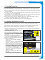
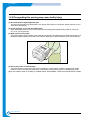

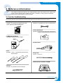
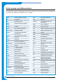

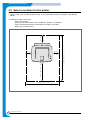
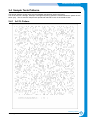


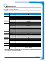
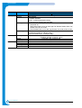
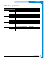
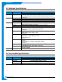
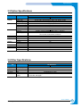

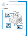
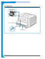
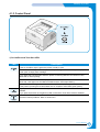

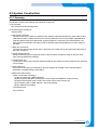
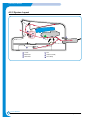


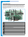

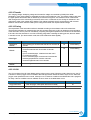
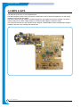
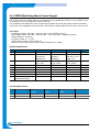


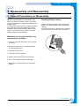
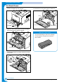

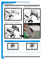
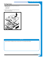


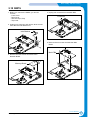
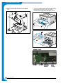

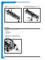
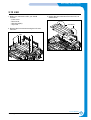
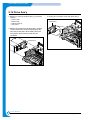

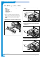
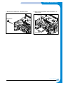
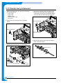


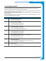

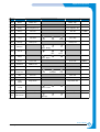
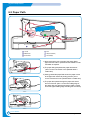
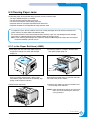
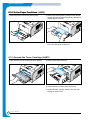
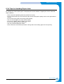

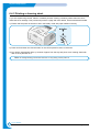

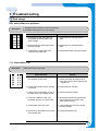


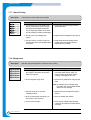

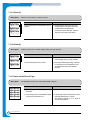
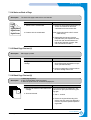
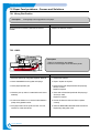
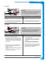


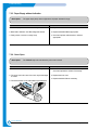
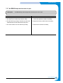
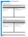

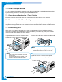
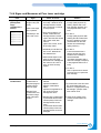

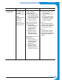
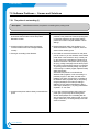
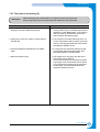
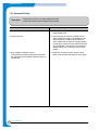


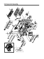


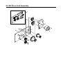
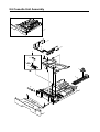


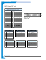


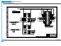


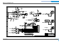
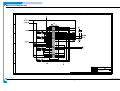

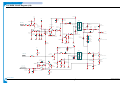

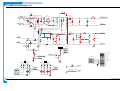

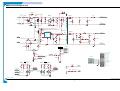


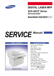
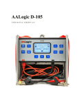
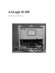

![[SPT-3000] e](http://vs1.manualzilla.com/store/data/005667089_1-a5f3766b3193f6552f250995926a69c5-150x150.png)