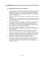
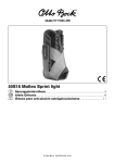
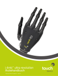
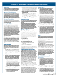
1
X-IST DataGlove
X-IST DataGlove Wireless
Users Manual
noDNA GmbH
Kronenstr. 70
10117 Berlin
Germany
Phone: +49 30 544915-38
Fax: +49 30 544915-39
[email protected]
X-IST DataGlove Manual
Copyright (C) 2009 by noDNA GmbH
Report your feedback to [email protected]
Manual Version 1.1.7
Visit the X-IST Web site: http://www.x-ist.de
- 2- of 85
Table of Contents
Table of Contents
[1] About this Manual...................................................................5
[2] Introduction...........................................................................7
[3] General concept of the DataGlove.............................................9
[3.1] General Overview:......................................................9
[3.2] Motion Capture Details:..............................................11
[3.3] Technology:..............................................................13
[4] Available Configurations:.......................................................15
[4.1] DataGlove/ADBox24 Versions:....................................15
[4.2] Additional Hardware Options:......................................16
[4.3] Additional Software Options:.......................................16
[4.4] Custom configurations:...............................................17
[5] Known limitations:................................................................19
[6] Commonly used abbreviations:...............................................21
[7] Technical Data:....................................................................23
[8] Sensor placements:..............................................................27
[9] Channel list of standard DataGlove configurations:....................37
[10] Wearing the DataGlove:.......................................................41
[11] Repair and Sensor Channel Def.:...........................................45
[12] Included parts:...................................................................46
[13] Optional parts:...................................................................50
- 3- of 85
Table of Contents
[14] Hardware Setup..................................................................53
[14.1] Connecting the cables..............................................53
[14.1.1] The USB cable .....................................................54
[14.1.2] The DataGlove (input device) cable..........................55
[14.2] The ADBox24 LEDs..................................................57
[14.3] The rechargeable battery..........................................58
[14.4] The Zigbee Pro wireless card.....................................60
[14.5] Quick start of ADBox24w..........................................62
[15] Software Installation...........................................................64
[15.1] Installing the ADBox24 USB Driver.............................64
[15.2] Removing the USB chip driver “FTDI” Software............70
[15.3] Installation of the “Sensor24” Software.......................71
[15.3.1] Sample rate tweaking in wireless mode....................72
[15.4] Installation of the “JGloveRaw” Software.....................75
[15.5] How to use “JGloveRaw” Software..............................76
[16] Firmware...........................................................................79
[17] Contacts............................................................................81
[18] Copyright...........................................................................82
- 4- of 85
About this Manual
[1] About this Manual
This manual describes the general usage of the X-IST DataGlove
and the X-IST ADBox24 (V5 series and higher) , the ADBox24w
(wireless) (V5 series and higher), their interfaces and the
available software.
If you have an ADBox24(w) older than V5, please use the manual
which came with your ADBox24(w) system.
It gives you a short introduction about the concept of the finger
action tracking and hand action tracking. It further shows the
hardware and software components, available options, how to
set them up.
Usage of the software modules is described in the software
manuals, if they exist, or in the help pages or readme files which
come with the software modules.
- 5- of 85
(this page is intentionally left blank)
- 6- of 85
Introduction
[2] Introduction
Welcome to the exciting world of motion capture!
Congratulations to your purchase of the X-IST DataGlove, an
advanced and affordable hand and finger action and pose
tracker.
The X-IST DataGlove is a product of noDNA, the designer and
manufacturer of the X-IST realtime products. New products are
available from time to time, check the website www.x-ist.de
frequently for new software downloads or information.
This user manual gives you an introduction to the setup and use
of the X-IST DataGlove. It helps you to understand the
components and their interconnection.
We will show how to wear the DataGlove and give a short insight
in some tips and tricks.
If you have any suggestions how to improve this documentation
or if you find errors please do not hesitate to note them towards
us at:
[email protected]
Thank you and now experience the X-IST DataGlove!
Your noDNA Support Team.
Berlin, 2009
- 7- of 85
(this page is intentionally left blank)
- 8- of 85
Concept of the DataGlove
[3] Concept of the DataGlove
Short general introduction to the DataGlove concept of human
finger and hand action and pose tracking:
[3.1] General Overview:
The DataGlove is named DATAglove, because it is capable to track
and digitize to data a variety of actions of a human hand ...and
because it looks like a GLOVE.
Electronic components and sensors are hidden inside the Glove.
They are mounted on top of a inner 2-way stretchable Lycra
glove which is covered by an outer glove to secure the sensor
electronics from the environment.
This “dual layer” design helps in manufacturing and servicing the
DataGlove. It is also an advantage if you do ergonomic research
and have to change the outer glove from time to time. The outer
glove is available in two different versions:
●
●
a “Perfect Grip” glove which is rubber coated on the inside
hand
a “Lycra/Elasthan” glove which is thin and stretchable
The DataGlove carries all sensors but no sensor post processing or
power supply electronics. This is the task of the ADBox24, the
sensor processor.
The ADBox24 is a 24 channel analogue/digital converter with USB
output. It is also available as wireless ADBox24w with switchable
USB/wireless output.
Usually a single cable connects the DataGlove with the ADBox24.
( Can be two cables in certain sensor options, such as the
DataGlove HR series)
The ADBox24 is designed to process the sensor data, supply the
sensors with power and transmit the processed data via USB cable
or optional wireless connection to the receiving computer
(currently Windows PC only, ask for Linux and Mac OS versions).
- 9- of 85
Concept of the DataGlove: General Overview
The ADBox24 can also be used also for MIDI (Musical Instrument
Digital Interface) output via USB or wireless, such as to control
musical instruments, light control consoles or other performance
oriented devices.
The tracked sensor data is available in realtime with no noticeable
lag of time. The data can be used for research, remote control,
computer animation, performance arts or music.
Compared to other tracking methods of other vendors of finger
motion tracking solutions, the X-IST DataGlove is very robust, can
be extended to two handed solutions with only one single cable
to the USB port of a PC and is completely powered by USB. ( or
by rechargeable battery with ADBox24w wireless transmission).
On top of this, the DataGlove with optional „Touch Sensors“ is the
first DataGlove to embed pressure sensitive fingertips.
The included software „Sensor24“ provides sophisticated „per
sensor calibration“, realtime gesture (pose) recognition and
file output.
See the list of features in the software section of this manual.
The Borland C++ SDK source code can be used for your projects.
- 10- of 85
Concept of the DataGlove: Motion Capture Details
[3.2] Motion Capture Details:
Currently the X-IST DataGlove captures
•
•
•
FINGER or FINGER joint up/down movements,
FINGERTIP pressure,
HAND pitch and roll rotation.
The DataGlove cannot capture (currently):
•
•
•
Hand rotation
Arm movements
Finger spread
A single DataGlove can capture the movement and pressure of
fifteen finger joints simultaneously with hand pitch/roll (DataGlove
HR3 3D).
Two DataGloves with a maximum of 12 sensor channels each can
be driven by the same processor box (ADBox24, ADBox24w) with
exactly the same sampling rate of a single glove.
Note: (only a single HR DataGlove can be used with a single
ADBox24(w) because the HR DataGlove takes two input ports of
the ADBox24(w)
The DataGlove PC software “Sensor24” makes this data available
for gesture recognition research, ergonomics or art and music
applications. This sensor data can i.e. drive any MIDI value and act
as controller for music use or it can be transmitted via LAN or COM
port or recorded to a ASCII text file for Excel or similar.
Note: currently you cannot use the Sensor24 software to control 2
ADBOX24(w) at the same time on the same computer
- 11- of 85
Concept of the DataGlove: Motion Capture Details
The X-IST DataGlove can capture angular changes of finger joints:
either the bend of each finger as a single value
(DataGlove/DataGlove SP1)
Here the outmost first finger joint is ignored, second joint and third
joint(knuckle) are measured as one single combined angle.
The thumb is different: outmost and second joint(knuckle) are
measured)
or it can capture each individual finger joint
(DataGlove HR, HR1, HR2, HR3)
Here you can optionally also capture the third Thumb joint in inside
hand (DataGlove HR1, HR3)
The X-IST DataGlove can capture the pressure at each fingertip
(TouchGlove, DataGlove SP1, HR2, HR3)
The X-IST DataGlove can optionally (3D option) measure the
pronation/supination and dorsalflexion/palmarflexion of the hand
towards the ground in a non restricted volume, it works
everywhere! This is achieved by two accelerometers which enable
a 2 axis rotation measurement in realtime. The range is +-90
(total 180) degrees!
Note: You can also order special sensor configurations and
placements as long as the total sensor count does not exceed 24.
- 12- of 85
Concept of the DataGlove: Technology
[3.3] Technology:
The finger movements are captured by patented bend sensors in
different lengths which are very robust, immune to humidity,
magnetic fields or light sources. The fingertip pressure is measured
by FSR pressure sensitive pads and the pronation and flexion of
the hand is measured by a 2 axis accelerometer.
The electronics are mounted on a PCB with SMD technology an are
located in a small Aluminium Box (ADBox24) which houses all
connectors and converts the analogue measurements into digital
signals and streams the digital signals to a serial USB interface.
The box is a bit lager than a mouse and can be placed on the
desktop while using the DataGlove. It is powered by USB.
The wireless version of the ADBox24 (ADBox24w) contains a
Zigbee (Digi-Maxstream Xbee Pro) wireless 2.4Ghz module which
enables node to node connection to a receiving computer with a
Zigbee USB receiver module (included in ADBox24w). The wireless
ADBox24w is powered by a rechargeable Battery pack or by USB
cable.
The ADBox24(w) is driven by a powerful ATMEL ATMega128 micro
controller with 16MHz. The ADBox24(w) is powered exclusively by
a MiniB-USB connector to which a power souce must be connected,
ie. A USB cable from the computer or a 4-9V stabilized wall pack or
charger with MiniB USB connector.
The ADBox24(w) can process one or 2 DataGloves/DataSoles with
a total of 24 realtime sensor channels.
If a DataGlove or DataSole contains more than 12 sensors (HR
series), the device connects to both ports of the ADBox24(w) and
by this only one device can be used at a time.
- 13- of 85
General concept of the DataGlove: Technology
Waste Electrical and Electronic Equipment (WEEE)
The X-IST product family is RoHS conforming to ensure lead free
and toxic free material use in production and products.
The environmental law EU 2002/96/EG require you
return this product to noDNA after lifetime or you hand it to a
official return collector of your region. Do not throw it in standard
trash.
- 14- of 85
Available Configurations: Hardware/Software Options
[4] Available Configurations:
[4.1] DataGlove/ADBox24(w) Versions:
All versions are available as right or left hand version in one size
which fits most hands (Size 10-11).
•
X-IST DataGlove:
5 bend sensors for finger movement tracking with 2 meter
cable and Sub-D HD 15 type male connector
•
X-IST TouchGlove:
5 pressure sensors at the finger tips to detect contact and
pressure
•
X-IST DataGlove SP1:
5 bend sensors and 5 pressure sensors at the finger tips
•
X-IST DataGlove HR:
14 bend sensors to detect finger joint movements
•
X-IST DataGlove HR1:
15 bend sensors to detect finger joint movements
(1 additional sensor in inner hand for third thumb joint)
•
X-IST DataGlove HR2:
14 bend sensors to detect finger joint movements
5 pressure sensors at the finger tips
•
X-IST DataGlove HR3:
15 bend sensors to detect finger joint movements
5 pressure sensors at the finger tips
(1 additional sensor in inner hand for third thumb joint)
•
X-IST custom built DataGlove
tell us which sensors you need at which places and we try our
best to manufacture this special DataGlove for your project.
- 15- of 85
Available Configurations: Hardware/Software Options
ADBox24 Versions:
•
ADBox24:
24 channels, 60Hz
Data Transfer by USB
Power supply by USB
•
ADBox24w:
24 channels, 55-60Hz
Data Transfer by USB and
Data Transfer by Zigbee Pro, wireless 2.4GHz
Power supply by USB or
Power supply by USB rechargeable battery pack or
Power supply by USB wall pack
[4.2] Additional Hardware Options:
All DataGloves:
• 3D option: adds 2axis accelerometer to any DataGlove,
enables tilt/vibration/acceleration measurement
•
Additional outer “Perfect Fit” Grip Glove (XL)
use this if you need good grip or humidity protection
•
Additional outer “Lycra/Elasthan” stretchable Glove (XL, or XXL)
use this for no sweat and best comfort, virtual/augmented
reality
- 16- of 85
Available Configurations: Hardware/Software Options
•
•
long DataGlove cable or cable extension
change of inner glove: noDNA can change the inner glove for
you if needed due to hygenic or worn issues.
ADBox24w:
•
extra rechargeable battery Li-Ion 2200mAh
[4.3] Additional Software Options:
•
SDK C++, Firmware Documentation, Java Raw write SDK
(SDK is included at no cost in wireless ADBox24w)
[4.4] Custom configuration:
The DataGlove is configured in many variations, each final product
is wired exactly to the ordered configuration. It is not possible to
add extra sensors or change sensor configuration after shipment.
If you feel you need a different configuration or additional sensors
we might be able to offer a trade in discount for you. Ask
[email protected] if this situation occurs.
An example:
We have manufactured a series of DataGlove HE (Hyperextension)
which have embedded additional sensors to measure the
Hyperextension (upwards move) of fingers at the knuckle of each
finger.
For new available options, versions and configurations, as well as
for new software downloads, please visit www.x-ist.de
- 17- of 85
(this page is intentionally left blank)
- 18- of 85
Known limitations
[5] Known limitations:
Although the X-IST DataGlove is a very powerful concept of
tracking human finger actions, there are some limitations:
Physical and mechanical limitations: due to the embedded
sensor concept some motions of a real person are limited by fabric
shape and size and by the structure of electronic components
inside the DataGlove.
Currently the DataGlove is coming on one size only. It might be too
tight or too loose for your hand even if we took a lot of care to use
a medium sized shape with as elastic material as possible.
Electronic limitations: the DataGlove carries one to three bend
sensor(s) and/or one pressure sensor per finger. There is –
currently - no way measuring the distance of two fingers with the
X-IST DataGlove Series. (Watch new product announcements.)
While pronation and flexion hand (rotate counter
clockwise/clockwise and rotate upwards/downwards) can be
measured in realtime (using the accelerometer 3D option),
currently there is no official option available to detect hand
abduction (rotate hand horizontally). If you need the abduction
measurement we might be able to provide a specially tailored
DataGlove for you.
The “3D option” accelerometer measures acceleration, this is why
hand movements in x y and z will return rotational values. The
data of the accelerometer is currently not filtered by hardware,
some firmware versions do software filtering, but in most cases
you will see the data noise if you look at the raw values. Use the
software realtime filter to smooth the output. The tilt filter has
from time to time a 1% (10 units) crosstalk to some sensor
channels. We try to fix this in upcoming versions.
Data noise is usually low or neglectable on all other sensors in USB
mode and there is a bit of noise in the wireless mode.
- 19- of 85
Known limitations
The pressure sensors have a range of 0-10kg. This range is very
non-linear (logarithmic). To compensate this you would need to
post process the data by your own linearising routine. The pressure
sensors are very sensitive in the low pressure range of 0-2kg and
then less sensitive to the rest of the range. We have implemented
a pressure lookup table in the Sensor24 software which you can
tailor to your needs and add new lookup entries. We have also
added thin aluminium plates to the sensors to improve stability
and repeatability of data generated. Still, these sensors are not
precise and not recommended if you need to have a precise
measurement.
Distance limitations: the DataGlove is coming with an attached
cable of about 2meters = (6 feet) which is designed to be inserted
into the ADBox24. Optionally there is a cable extension available,
but be aware of increasing noise in the data due to cable length.
The ADBox24 is coming with USB output which is usually no
problem to be extended to any length using repeater electronics.
USB is only good for 2-3 meters (>= 1-2 meter cable included)
and should be run through a repeater if needed longer than this.
Using the wireless ADBox24w transmission there might be data
transmission stops or drops when your system refreshes, when
other devices are detected in the same frequency (2.4 GHz is used
by GSM phones, mobile phones, bluetooth devices, WLAN WIFI
wireless lan devices, Microwave ovens) or the distance between
ADBox24w and receiving USB unit is too large or obstructed by
several walls.
If you experience dropouts, then it is best to
1) Check if there are mobile telephones, wireless lan devices,
Micro Wave ovens or any other 2.4 GHz frequency emitting
devices and switch them off to see if they cause
interference
2) Change the COM port settings of the Xbee USB module in
the Control panel of Windows (latency time)
3) reduce the amount of load on the computer ( stop
unnecessary services) or/and
4) increase the priority of the process with the task manager
- 20- of 85
Commonly used abbreviations
[6] Commonly used abbreviations:
noDNA
X-IST
DG
MIDI
PCB
POT
SMD
USB
nc
ADBox24
=
=
=
=
=
=
=
=
=
=
(speak: no D N A, no genetic code, artificial)
(speak: exist; Motion Capture Product line of noDNA)
DataGlove
Musical Instruments Digital Interface
Printed Circuit Board
analogue potentiometer (variable resistor)
Surface Mounted Device, small semiconductors
Universal Serial Bus
not connected
Analogue Digital converter box for 24 channels
(named “GloveBox” until June 2006)
ADBox24w = wireless version(s) of Analogue Digital converter
box for 24 channels
- 21- of 85
(this page is intentionally left blank)
- 22- of 85
Technical Data
[7] Technical Data:
DataGlove
• black/grey Glove (one size -size 10/11- fit all) with
embedded sensors
• inner glove in silk/cotton mix or Lycra.
• outer glove with selectable a) special latex Grip coating on
hand inside or b) Lycra stretchable glove
• about 200 gr total weight including cable
• maximum of 24 sensor channels (DOF)
• 0-20 bend sensors or/and 0-20 pressure sensors per glove
• maximum of 4 additional sensors 0-5V or
• optional 2 axis tilt sensor (x/y +-90 degrees)
• available for left or right hand
• with 2 meter (6-7 feet) cable, Sub_D HD 15 pin male
connector
• serviceable
ADBox24/ADBox24w
• Aluminium housing, EMV shielded
• 3 coloured LEDs (V4), one multicoloured LED (V5)
• about 140 gr total weight (without cables and power supply)
• 1 USB type Mini B Port (5pin)
• USB connector cable (2 meter/ 6-7 feet) TYPE A male to
TYPE Mini B 5pin male
• 2 input ports (GlovePorts) Sub-D HD 15 pin female for
DataGloves/DataSoles
• Resolution 10 bit internal, supplied sensor data 10 bit or 8 bit
(Data Mode), 7 bit (MIDI Mode)
• Sampling Rate ADBox24: 60 Hz per sensor,
• Sampling Rate ADBox24w (Zigbee): 54-60Hz per sensor
• maximum number of sensor channels: 24
• ADBox24w Zigbee: Digi-Maxstream XBee Pro Module,
2.4GHz, 1km outdoors, wire antenna
- 23- of 85
Technical Data
Power Supply
• by USB 5V only (V4), by USB 4V-9V (V5)
• (V5 wireless only) by rechargeable battery pack, 4-9V
• (V5 wireless only) by included 5V wall pack
• ADBox24 power consumption typical: 60 mA
• ADBox24w power consumption typical: 150mA
Range (wireless)
• up to 100m indoors, 1000m outdoors
Interfaces
• USB 2.0 with USB cable TYPE A to TYPE Mini B (included)
• 2 GlovePorts with up to 12 sensor channels each
Environment temperature
• Standard 0..50 degrees Celsius
- 24- of 85
Technical Data
X-IST DataGlove WIN PC Software “Sensor24”
• supports ADBox24 and ADBOX24w
• supports USB, TCP/IP and COM input
• 24 realtime sensor channels
• graphical viewer
• Firmware can be updated via USB
• MIDI commands can be assigned freely to each channel
• MIDI commands can be assigned freely to each gesture
• Load, save and edit sensor templates
• Load, save and edit calibration templates
• Load, save and edit gesture (pose detection) templates
• Load, save and edit filter templates
• realtime (approximate!!) conversion calculation of angles,
pressure
• Naming of individual sensors
• Naming of individual gestures (poses)
• calibration of each sensor channel
• filtering of each sensor channel
• invert sensor data function for inverted data
• Gesture pose recognition (24) of any sensor setup
• Save data files with sensor data, gesture data, timestamp
• Realtime data output via COM port (115k) or TCP/IP to
localhost or any LAN PC
• File format self configurable
• Multi language user interface, user can add a new language
• Integrated Help files
• Open source code for all data (Borland C++)
- 25- of 85
(this page is intentionally left blank)
- 26- of 85
Sensor placements
[8] Sensor placements:
Here you see the placement of sensors within the DataGlove.
Depending on your DataGlove configuration you have any
combination or even a special setup of sensors.
All sensors are wired with high flex silicone cables and all wire
combine at the outer side of the hand (where the little fingerpinkie is) to one (DataGlove, TouchGlove, DataGlove SP1) or to
two cables (DataGlove HR series) which run(s) to the ADBox24(w).
- 27- of 85
Sensor placements
This image shows the long bend sensors. Each finger has one bend
sensor which is placed in a way to measure the first two joints. The
third joint is not measured.
The value of the both joints of a finger combines a total value of
curvature. This means you get one value per finger.
These sensors are used in the DataGlove and the DataGlove SP1
- 28- of 85
Sensor placements
Here you see the placement of sensors within the DataGlove HR.
Depending on your DataGlove configuration you have any
combination or even a special setup of sensors.
All sensors are wired with high flex silicone cables and all wire
combine at the outer side of the hand (where the little fingerpinkie is) to two cables which run to the ADBox24 and plug into
Port 1 and 2.
This image shows the 14 bend sensors. Each finger joint has one
bend sensor which is placed in a way to measure the desired joint.
The third joint of the Thumb is not measured (available in
DataGlove HR1/HR3).
- 29- of 85
Sensor placements
Here you see the inside of the hand. Below the fingertips is the
location of the pressure sensors. These sensor actually measure
the pressure applied to them, so they can act as a switch as well as
a controller proportional to the pressure. This enables you to
actually measure force (max 10kg) applied to the tip of the
fingers.
Note: the pressure sensors are extremely non-linear and
you cannot use them for accurate pressure measurements.
Pressure sensors are used in TouchGlove, DataGlove SP1,
DataGlove HR2 and HR3
- 30- of 85
Sensor placements
Information:
Although the pressure sensors are located at the inside of the
hand, the cables to and from the sensors run over your fingertip to
the upper side of your hand where they run downwards the finger
and unite at the back of your hand. This enables you to work with
the DataGlove without applying pressure or force to the embedded
cables.
- 31- of 85
Sensor placements
Here you see the location of the 2axis accelerometer for tilt and
vibration measurements. It sits in the middle of the back of your
hand.
The two axis which can be measured are up/down and left/right
tilt. (Currently you cannot measure rotation of the hand in zdirection.)
The Tilt sensor option (3D option) can be ordered to any DataGlove
or DataGlove HR
- 32- of 85
Sensor placements
This you can measure:
hand tilt up down (pronation)
- 33- of 85
Sensor placements
This you can measure:
hand tilt left right (flexion)
- 34- of 85
Sensor placements
This you cannot measure hand rotate left/right (abduction):
- 35- of 85
(this page is intentionally left blank)
- 36- of 85
Channel List of standard DataGlove configurations
[9] Channel list:
DataGlove: (if plugged into PORT 1, add +10 for PORT 2)
•
•
•
•
•
Channel
Channel
Channel
Channel
Channel
1
2
3
4
5
Bend
Bend
Bend
Bend
Bend
Thumb
Index
Middle
Ring
Pinkie
TouchGlove: (add +10 for PORT 2)
•
•
•
•
•
Channel
Channel
Channel
Channel
Channel
6
7
8
9
10
Pressure
Pressure
Pressure
Pressure
Pressure
Thumb
Index
Middle
Ring
Pinkie
DataGlove SP1: (add +10 for PORT 2)
•
•
•
•
•
•
•
•
•
•
Channel
Channel
Channel
Channel
Channel
Channel
Channel
Channel
Channel
Channel
1
2
3
4
5
6
7
8
9
10
Bend Thumb
Bend Index
Bend Middle
Bend Ring
Bend Pinkie
Pressure Thumb
Pressure Index
Pressure Middle
Pressure Ring
Pressure Pinkie
- 37- of 85
Channel List of standard DataGlove configurations
DataGlove HR: (1 ist outmost joint, 2=middle, 3= inmost)
•
•
•
•
•
•
•
•
•
•
•
•
•
•
•
Channel
Channel
Channel
Channel
Channel
Channel
Channel
Channel
Channel
Channel
Channel
Channel
Channel
Channel
Channel
1
2
3
4
5
6
7
8
9
10
11
12
13
14
15
Bend Thumb 1
Bend Thumb 2
not connected (nc)
Bend Index 1
Bend Index 2
Bend Index 3
Bend Middle 1
Bend Middle 2
Bend Middle 3
Bend Ring 1
Bend Ring 2
Bend Ring 3
Bend Pinkie 1
Bend Pinkie 2
Bend Pinkie 3
DataGlove HR1: (1 ist outmost joint, 2=middle, 3= inmost)
•
•
•
•
•
•
•
•
•
•
•
•
•
•
•
Channel
Channel
Channel
Channel
Channel
Channel
Channel
Channel
Channel
Channel
Channel
Channel
Channel
Channel
Channel
1
2
3
4
5
6
7
8
9
10
11
12
13
14
15
Bend
Bend
Bend
Bend
Bend
Bend
Bend
Bend
Bend
Bend
Bend
Bend
Bend
Bend
Bend
Thumb 1
Thumb 2
Thumb 3
Index 1
Index 2
Index 3
Middle 1
Middle 2
Middle 3
Ring 1
Ring 2
Ring 3
Pinkie 1
Pinkie 2
Pinkie 3
- 38- of 85
Channel List of standard DataGlove configurations
DataGlove HR2: (1 ist outmost joint, 2=middle, 3= inmost)
•
•
•
•
•
•
•
•
•
•
•
•
•
•
•
•
•
•
•
•
Channel
Channel
Channel
Channel
Channel
Channel
Channel
Channel
Channel
Channel
Channel
Channel
Channel
Channel
Channel
Channel
Channel
Channel
Channel
Channel
1
2
3
4
5
6
7
8
9
10
11
12
13
14
15
16
17
18
19
20
Bend Thumb 1
Bend Thumb 2
nc
Bend Index 1
Bend Index 2
Bend Index 3
Bend Middle 1
Bend Middle 2
Bend Middle 3
Bend Ring 1
Bend Ring 2
Bend Ring 3
Bend Pinkie 1
Bend Pinkie 2
Bend Pinkie 3
Pressure Thumb
Pressure Index
Pressure Middle
Pressure Ring
Pressure Pinkie
- 39- of 85
Channel List of standard DataGlove configurations
DataGlove HR3: (1 ist outmost joint, 2=middle, 3= inmost)
•
•
•
•
•
•
•
•
•
•
•
•
•
•
•
•
•
•
•
•
Channel
Channel
Channel
Channel
Channel
Channel
Channel
Channel
Channel
Channel
Channel
Channel
Channel
Channel
Channel
Channel
Channel
Channel
Channel
Channel
1
2
3
4
5
6
7
8
9
10
11
12
13
14
15
16
17
18
19
20
Bend Thumb 1
Bend Thumb 2
Bend Thumb 3
Bend Index 1
Bend Index 2
Bend Index 3
Bend Middle 1
Bend Middle 2
Bend Middle 3
Bend Ring 1
Bend Ring 2
Bend Ring 3
Bend Pinkie 1
Bend Pinkie 2
Bend Pinkie 3
Pressure Thumb
Pressure Index
Pressure Middle
Pressure Ring
Pressure Pinkie
DataGlove 3D option: (PORT1, default)
• Channel 21
• Channel 22
rotate y (Hand turn right/left)
rotate x (Hand up/down )
DataGlove 3D option: (PORT2)
• Channel 23
• Channel 24
rotate y
rotate x
- 40- of 85
Wearing the DataGlove
[10] Wearing the DataGlove:
Difference between “Inner” Glove and “Outer” Glove
Your hand will go into the inner Glove.
The inner Glove is to protect the sensors from being touched by
your hand, the outer Glove is to protect the sensors from the
outside world.
Beware of stretching the DataGlove, especially when you
put him off:
The DataGlove is flexible to fit most hands and to support and
operate different kind of sensors. This is good and makes the
DataGlove comfortable to wear. The disadvantage of stretchable
material is that you might rip off internal cables by stretching the
fingers too hard.
- 41- of 85
Wearing the DataGlove
To take off the DataGlove you loosen it from the palm side of the
Glove towards your fingers. Then you loosen it finger per finger
about 1/3rd of the finger length, then loosen it from the palm and
back hand side again, next 1/3rd of all fingers and so on.
- 42- of 85
Wearing the DataGlove
Hygienic issues:
You can use disinfectant spray carefully for the inside glove. The
outer Glove can be wiped off with a damped cloth, make sure it
is NOT wet.
Damage issues:
The inner Glove cannot be replaced by you because it holds the
sensors. If needed, oDNA can change the inner Glove for you.
The outer Glove is replaceable by noDNA service or skilled staff.
You can use any outer Glove as long as it does not hinder the
sensors.
- 43- of 85
(this page is intentionally left blank)
- 44- of 85
Repair and Sensor Channel definition
[11] Repair and Sensor Channel Def.:
If a sensor or sensor channel is broken or does not supply any
signal you can send in the DataGlove for repair. There is a flat
fee per sensor channel for repair/replacement of the sensor.
(shipment costs extra) This ensures you can use the DataGlove
for a long time and do not need to worry if something happens.
We can also renew the inner glove for you if needed.
Write to [email protected] if you need any repair
information.
Sensor channel definition:
A sensor channel describes how much realtime data channel a
sensor covers. Currently all channels of the DataGlove are
analogue voltages of the sensor outputs. This is why for
each individual sensor output you need one channel.
A bend sensor supplies all values in one channel, as you bend the
sensor the values of this channel will change.
A pressure sensor supplies all values in one channel, as you
apply force to pressure pad of the sensor the values of this
channel will change.
A 2axis accelerometer supplies the values of one axis in one
channel and the values of the other axis in another channel. This
is why this sensor takes 2 channels.
Bend Sensor
=
Pressure Sensor
=
2axis accelerometer (tilt sensor) =
- 45- of 85
1 channel
1 channel
2 channels
(this page is intentionally left blank)
- 46- of 85
Included parts
[12] Included parts:
•
Software CD with Software, Tools and Manuals
Software CD
•
X-IST ADBox24 or ADBox24w (wireless)
(to process DataGlove Sensor Data)
ADBox24 USB version, silver brushed (V4)
- 47- of 85
Included parts
ADBox24w (wireless version, black anodized) (V5)
•
USB Cable to connect the ADBox24 with a computer, currently a
Windows PC. USB cable type: A to MiniB, 2m
USB Connector Cable
- 48- of 85
Included parts
•
X-IST DataGlove
(most versions look same from the outside)
(HR versions have 2 cables)
X-IST DataGlove
•
Rechargeable Battery Pack 5V ,
(wireless ADBox24w only) (this or similar)
- 49- of 85
Included parts
•
International Wallpack 5V for charging the battery pack or
driving the ADBox24w (wireless ADBox24w only)
(this or similar)
•
Zigbee USB Module (with USB cable) preconfigured to point to
point communication (wireless ADBox24w only)
- 50- of 85
Optional parts
[13] Optional parts:
•
extra rechargeable battery pack (to be used with wireless
version only).
•
Extra international wall pack 5V (to be used with wireless
version only).
•
extra outer “Perfect Grip” Glove, XL
•
extra outer “Lycra” glove, strechable, black, XL or XXL
•
extra long cable of DataGlove (ask upon order)
•
cable extender (ask)
•
Sensor cable with attached sensor(s) of any kind
•
renewal of inner glove (send in glove to us)
- 51- of 85
(this page is intentionally left blank)
- 52- of 85
Hardware Setup
[14] Hardware Setup
[14.1] Connecting the cables
The X-IST ADBox24 can be connected to:
•
•
USB Cable
DataGlove/DataSole Cable(s)
The X-IST ADBox24w (wireless) can be connected to:
•
•
•
•
USB Cable
Battery Pack
external Power Supply Wall Pack
DataGlove/DataSole Cable(s)
- 53- of 85
Hardware Setup
[14.1.1] The USB cable
The USB Cable is attached to the back side of the ADBox24 and
your computer.
It provides power for the ADBox24 and enables the data transfer
from and to the ADBox24. It is USB2.0 capable and has a USB
Type A to USB Type Mini USB 5 pin connector. It is EMI/RFI
shielded, fully moulded and has strain relief.
Please note: Use the original USB cable only. There are 4pin cables
available on the market which will not work with the ADBox24(w)
This should be your usual configuration, plug USB cord here:
While using a ADBox24w the USB cable can be for two purposes:
• to provide power for the ADBox24w in wireless mode, no data
transfer via USB but via wireless connection
• to provide power to the ADBox24w in USB mode and do the
data transfer via USB cable.
- 54- of 85
Hardware Setup
[14.1.2] The DataGlove (input device) cable
All DataGlove versions and upcoming products for the ADBox24
are connected through Port 1 and 2 (technically 0 and 1) on the
front side of the ADBox24(w). The Ports are identical, so you can
plug in you device wherever you like, but we recommend to do it
the way we suggest in this manual for continuity and easy
support.
Port 2
Port 1
Connect here your right hand DataGlove (sensor
channels 1-12, logically 1-10,21,22)
(you can plug it into the other port as well, sensors
channels will be 13-24, logically 11-20,23,24)
Port 1 is usually the right hand port because located on
the right side of the lower end of the ADBox24(w)
- 55- of 85
Hardware Setup
The ports are equipped with Sub-D HD 15 pin female connectors,
this is why your input device carries a Sub-D 15 pin male
connector.
To tighten the fit, you can use the two screws of the male cable
connector metal EMI shielded housing.
If you have a DataGlove HR or any other device which comes
with two connector cables and two plus, make sure you do not
mix plug 1 and 2. Although there would be no electronic
problem, the sensor channels will set differently and your
application might not work.
- 56- of 85
Hardware Setup
[14.2] The ADBox24 LEDs
The ADBox24(w) V5 holds an RGB LEDs on the upper side of the
box.
The colours:
USB Mode: starts with a color sequence
GREEN/RED GREEN/BLUE GREEN/RED/BLUE
then stays on GREEN/RED (Orange) until data is polled
from the box which switches it to GREEN
WIRELESS Mode: starts with a color sequence
BLUE/RED BLUE/GREEN GREEN/RED/BLUE
then stays on BLUE/RED (Magenta) until data is polled
from the box which switches it to BLUE
A simultaneous green/blue/orange LED short pulse marks every
1000 samples sent. With a speed of about 50Hz this is every 20
seconds. You should expect a pulse every 16-20 seconds.
Additional colors: RED = Error
- 57- of 85
WHITE = Box HW/SW Version
Hardware Setup
[14.3] The rechargeable Li-Ion battery power supply
The ADBox24w has no other power input than the USB port on
the backplane. The ADBox24w has no built in batteries.
To provide power to the wireless ADBox24w you can use the USB
cable and drive it from a PC or Laptop. Make sure you have no
other power consuming devices attached to the same USB hub as
you might exceed the maximum power draw.
In portable applications where a USB cable cannot be used you
need the rechargeable 5V battery which comes with the
ADBox24w or you can use the 5V Wall Pack or any power supply
with 4-9V
This (ADBox24 V5) USB port accepts
NO OTHER VOLTAGE than 4-9V!
Damage to the ADBox24w will occur if you supply any other
voltage through this port.
The included portable Power Pack is a very powerful
rechargeable battery with a USB Mini B connector for power
input (charging the battery pack) and USB Type A plug as power
output to the ADBox24w.
If you need another power pack, this is available as option.
- 58- of 85
Hardware Setup
Charging the battery pack:
Do not use the battery pack while charging!
You can charge the battery Pack by plugging a USB cable to the
IN port at the bottom of the rechargeable battery.
Use your PC USB port (slow charge, max 500mA) or the included
Wall Pack (fast charge, 1A)
Charging takes about 6 hours. While charging is in progress
you see the a red light on the front of the battery.
As soon as the red light has changed to a constant, non blinking
lit green light, charging is completed.
If by any reason you want to discard the battery pack, do not
throw it in fire or in standard waste of your house. Return it to
noDNA or to an official collectors place in your region for
electronic waist or a battery collector in your local electronic
market store.
- 59- of 85
Hardware Setup
[14.4] The wireless Zigbee Pro Card
The ADBox24w black edition is equipped with Zigbee wireless
standard (Digi-Maxstream XBee Pro) modules. These modules
are very small, powerful, reliable and standardized throughout
the world. They work in the 2.4 GHz bandwidth which is already
populated by wireless LAN (WIFI) and bluetooth. They use a very
small frequency band and different channels.
The Digi-Maxstream XBee Pro module of the ADBox24w is
soldered onto the Motherboard and is not accessible at all. The
only indication for the plugged-in card is the small antenna which
is pointing through a hole in the backpanel of the ADBox24w.
Do not pull, bend or cut the wire antenna.
Use the switch to switch between USB cable data mode
(inwards) or wireless Zigbee Pro mode (outwards). Reconnect
power after switching to initialize the ADBox24w to this mode.
- 60- of 85
Hardware Setup
LED sequence stops with orange or green if USB data transfer is
selected and with magenta or blue if wireless data transfer is
selected.
Use the USB port to provide power by a USB cable or USB power
supply (4V-9V) or the rechargeable battery pack.
WARNING: never use any other power than 4-9V!
This image shows USB XBee module for the USB port of the PC.
The task of this device is to provide the wireless communication
from your PC to the ADBox24w.
It is preconfigured by noDNA. Do not reprogram it. It will not pair
to the Digi-Maxstream Xbee Pro module embedded in the
ADBox24w anymore.
There is no way to reprogram the embedded module in the
ADBox24w.
WARNING: Beware of putting this module on metallic objects
because the pins are not covered by a housing and might short
circuit.
- 61- of 85
Hardware Setup
[14.5] Installation of the ADBox24w and USB module:
1) Make sure there is no old FTDI Driver (USB chip) on your
system:
• Unplug ALL USB devices
• Use the FT Clean utility on the DataGlove CD to remove all
old FTDI chip drivers
2) Install the ADBox24w driver:
• This driver is not needed for wireless operation, but for USB
data transfer, so you want to install it.
• Unplug ADBox24w if USB cable or power is plugged in.
• Switch the Mode switch on the back of the ADBox24w
towards the USB connector (USB data transfer mode)
• Provide Power to the ADBox24w (plug in USB cable or Power
supply)
• Install the driver from the DataGlove CD (ADBox24 Driver, is
located on DataGlove CD/ADBox24_Driver/CDM....)
(has to be done twice, once for the driver, once for the
virtual serial port)
3) Unplug the ADBox24w from power
4) Install the USB module
• make sure the ADBox24w is unplugged!!
• Plug in the USB cable to the USB Module and connect it to
your PC, a red light will blink
• Install the driver from the DataGlove CD when asked (in
Directory: For wireless ADBox24 only, Driver for Xbee Pro
USB box directory)
• When it asks to replace an already installed file which is
newer than the file to be installed, reply NO
(has to be done twice, once for the driver, once for the
virtual serial port)
• Check your system manager/hardware/device
manager/Ports, look for the new COM Port and remember
the COM Port Number
5) Activate ADBox24w in wireless mode
• Pull the switch of the ADBox24w away from USB (wireless
mode)
• Provide Power to the ADBox24w
- 62- of 85
Hardware Setup
5) there will be an initial blinking sequence which ends in a
magenta (blue and red) color, this means wireless, no data
transfer
• now go to the PC and start Sensor24
• never start it from CD, copy the whole Sensor24 directory to
your local harddrive
• In Preference/Input Interface Configuration select the COM
Tab, select the COM Port of the USB Module (XBee USB
module), click Accept
• In Preference/Interface Selector select COM, click Connect
Now you are in wireless mode! You see the color light of the ADBox24w
changes to blue (wireless, data is transfered)
6)
•
•
•
•
•
To switch to USB Mode:
close Sensor24
unplug the ADBox24w from power
switch the switch on the back of ADBox24w downwards
plug in the USB cable from PC to ADBox24w
(ADBox starts with a light sequence then the light will be
orange (USB mode, no data transfer ADBox is waiting for
Sensor24 software data poll command)
• start Sensor24
• In Preference/Interface Selector select USB, click Connect
Now you are in USB mode! You see the color light of the ADBox24w
changes to green (USB mode, data is transfered)
- 63- of 85
Software Installation: ADBox24 USB Driver
[15] Software Installation
General Information:
Available Software for the DataGlove/ADBox24 currently:
•
Sensor24
(main application software, Windows)
•
JGlove (Java language GUI program)
•
Hand (C++ language GUI program, discontinued)
•
JGloveRaw (Java language raw data recorder)
•
SDK (Borland C++ and old Java version)
Available Software for the DataGlove/ADBox24w currently:
•
Sensor24
We recommend using Sensor24
All other software packages are not supported anymore and
might not work with your firmware of the ADBox24.
- 64- of 85
Software Installation: ADBox24 USB Driver
[15.1] Installing the ADBox24 USB Driver
Please follow the setup instruction to install the necessary USB
driver for your ADBox24.
As soon as you connect the USB cable of the ADBox24 to your
computer, the Hardware Wizard will automatically start.
Select: No, not this time and click on Next...
Insert your DataGlove Software CD in your CD-ROM device
Select: Install from a list or specific location (Advanced)
and click on Next...
- 65- of 85
Software Installation: ADBox24 USB Driver
Select: Search for the best driver in these locations.
Select: Search removable media (floppy, CD-ROM...)
OPTIONAL for (Advanced) 3. Select: Include this location in
the search (point to your CD Drive)
and click on Next...
- 66- of 85
Software Installation: ADBox24 USB Driver
If the system does not find the driver go Back and use Browse to
point to your CD drive/ADBox24 Driver/CDM.... directory
- 67- of 85
Software Installation: ADBox24 USB Driver
If this window is coming up please click on: Continue Anyway
the FTDI FT8U2XX Device is the chip from the ADBox24.
- 68- of 85
Software Installation: ADBox24 USB Driver
Click on:
Finish to end the Hardware wizard.
- 69- of 85
Software Installation: Remove FTDI
[15.2] Removing the USB chip driver “FTDI” Software
Best is to use the FT CLEAN utility on your CD.
follow the instructions of FT CLEAN after clicking on FTClean.exe
Îf not possible then do this:
Go to: My Computer, select Add or remove programs.
Select „FTDI“ and click on Change/Remove, accept with
Yes
and the program will be removed.
- 70- of 85
Software Installation: „Sensor24“
[15.3] Installation of the “Sensor24” Software
Sensor24 is the main software with graphical user interface for
the DataGlove/DataSole with ADBox24(w).
To install, copy the Sensor24 Application directory to your local
disk. Do not run it via a network, do not run it from CD because
it needs to write template files.
Make sure the ADBox24.dll and FTD2XX.dll are always located in
your directory where the Sensor24.exe is.
The Templates directory holds all Templates of your DataGlove
settings, calibration/filter settings and more. There is also a
factory backup directory of the Templates
Use the internal Help pages to get assistance on functions.
To start the application:
Connect a DataGlove to the ADBox24 and plug in the USB cable.
Click Sensor24.exe, then select your
Input device Selector (USB) and press connect.
Note: The Sensor24 software makes extensive use of templates.
There are templates already preconfigured for all standard
DataGloves. To load a template for your DataGlove go to
File/Load Settings/Load all settings and select the xxxx.gcfg file
If you have a wireless ADBox24w:
Hook up your XBee USB Module with USB cable to your PC
Check which COM Port is being used by the USB Module in your
control panel/system/hardware/LPT and COM Ports listing
Power up the ADBox24w by USB cable or battery pack
Start Sensor24 (not from CD!!! but from harddisk)
Select the COM port of above in the Input Configuration of
Sensor24
Select Input device Selector (COM/Zigbee) and press connect.
- 71- of 85
Software Installation: „Sensor24“
[15.3.1] Sample rate tweaking in wireless mode
A disadvantage of the FTDI USB chip driver is that it sets a buffer
delay of 16ms as default. For our realtime application this is too
slow.
As a result the light does flicker (data transfer slow) while polling
data with Sensor24. Whenever you see a constant flickering light
on the ADBox24(w) this means you need to improve the driver
settings to gain more update speed of data.
The ADBox24(w) flashes with all 3 LEDs every 1000 sample
blocks done. This is a bit hard to see because it should not
bother you during normal operation.
(A sample block here means: a package of all 24 sampled sensor
inputs, so it actually flashes after 24000 samples)
Use a stop watch to measure the time between two flashes.
It should be about 16 seconds in USB mode (1000/16=63Hz)
and 16-20 seconds in wireless mode (1000/20 = 50Hz)
If the duration is longer, check your COM Port settings in the
System manager/Hardware Tab:
- 72- of 85
Software Installation: „Sensor24“
The ADBox24w and the USB module uses
115kBaud,8bit,1 Stopbit,No Parity, Hardware flow control (CTS
on)
To tweak settings of your COM port FTDI driver, please click on
the ADVANCED SETTING
- 73- of 85
Software Installation: „Sensor24“
Change the LATENCY, (default is 16), lower number means less latency,
faster. It can be that 1 is working fine but it might be also that this is too
fast for your other system processes. Try out 8 or 6 then.
If you see jerky data or data spikes every couple of seconds, adjust the
Timeout tab do 100 for Minimum Read and 100 for Minimum write and
see if this fixes it, usually it does and you can further tweak these
settings for best performance and stability.
Note: After tweaking the settings, disconnect and reconnect the
ADBox24(w) or USB Module to power, so that the settings are used by
the PC
Note: whenever you switch to another USB port you need to set these
settings again.
- 74- of 85
Software Installation: „JGloveRaw“
[15.4] Installation of the “JGloveRaw” Software
JGloveRaw is a raw data write software, written in Java.
The software is included in your Software Developer Kit.
It does not change your registry, so it can be installed and
deleted without any trace or change to your system.
Currently it does not support ADBox24w (wireless).
Prerequisites:
JGloveRaw software requires Java Runtime environment to be
installed on your computer. If you do not know if you have Java
installed go to your DOS input prompt menue and enter:
java
If you get a long response of input options, Java is installed. If
you get a command not found error, you need to install Java.
Installing Java: go to the CD directory “JGlove distribution” and
enter the directory Java Runtime. Install the executable.
For JGloveRaw operation, the ADBox24 driver needs to be
installed, see sections above about how to install the ADBox24
driver.
Installation:
Copy the JGloveRaw directory to any location you like, such as
your Programs directory.
Change the .bat file to your needs. Double clicking the .bat file
will start the raw write of the ADBox24 Data to a file.
Press “CTRL C” to stop the record.
Please note: the .bat file has to be located where it is now. It
always looks for a subdirectory nodna. If not present, the
application will not start and you get an error message.
Please note: files can get big very fast because they are not
compressed, ASCII, and can be edited with any Text Editor.
Please follow the instructions in the next chapter for operation
instructions.
- 75- of 85
Software Installation: „JGloveRaw“
Uninstall:
To uninstall simply delete the JGloveRaw directory.
[15.5] How to use “JGloveRaw” Software
Prerequisites:
You need to have Java Runtime environment (JRE only, the SDK
is not needed) installed on your computer.
One version is included in the Java Runtime directory of your
JGlove distribution on the CD
Here is an older online version:
http://java.sun.com/j2se/1.4.2/download.html
After installation check if Java works:
In the Dos shell enter: java
You should see a long response.
If you get a short error message something went wrong.
Usage:
Do not move the JGloveRaw.bat file to any other location. It
looks for a subdirectory nodna. If not found, it will not work.
You can rename the file to your needs of course.
Now either edit and use the batch file (JGloveRaw.bat) or
start the programm directly in execution panel with:
java nodna.JGloveRaw -c <channels>
Options:
--help, -h show this help
--channel, -c display this channel(s)
Examples for display of data from ADBox24 on screen:
java nodna.JGloveRaw -c 1..5,10..15,21,22
java nodna.JGloveRaw -c 1..5 -c 10..15 -c 21 -c 22
- 76- of 85
Software Installation: „JGloveRaw“
Examples to write a file of data from ADBox24
java nodna.JGloveRaw -c 1..5,10..15,21,22 > outfile.csv
java nodna.JGloveRaw -c 1..5 -c 10..15 -c 21 -c 22 > outfile.csv
Stop output to screen or file by pressing <CTRL/STRG> <C>
Data Format:
Timestamp (Unix Timestamp in milliseconds since 1970),
Channel x1 Data, Channel x2 Data,...., Channel xn Data
- 77- of 85
(this page is intentionally left blank)
- 78- of 85
Firmware
[16] Firmware
Usually there is no reason to reinstall or upgrade the firmware.
NOTE: ADBox24 V5 Firmware update will change, we will provide
information as soon as it is available. You will not be able to
update the Firmware with Sensor24 software anymore.
ADBox24 V4 Firmware update procedure:
To download a new Firmware into the ADBox24(w) connect the
ADBox24 via USB to the Windows PC, do not use wireless mode.
Start “Sensor24” Software.
Select Firmware download from OPTIONS selector in the top Menu
Bar.
Click on Firmware Button and point to the main_Vx.hex file
(firmware file).
Click download. A progress bar will appear. If it stops before end,
then watch the ADBox24(w) after a while it will blink, sometimes
nervously. This is the time to close the Download window and
Sensor24.
Unplug the ADBox24(w) from power and plug it in again. This
initializes the new Firmware.
WARNING:
Do not interrupt the download to ADBox24(w) process! If
interrupted you might not be able to download any firmware into
the ADBox24(w) anymore and will have to send it to noDNA for
reinstalling.
- 79- of 85
Contacts
[17] Contacts
Please use the following addresses for getting in contact with
noDNA for X-IST product support.
This assures the fastest possible feedback for your request.
E-Mail Address
Purpose
[email protected]
[email protected]
Only license requests for new
installations or relocation. Do
not report license troubles
here.
Any documentation issues,
bugs, corrections of printed or
online documents.
All general support questions.
[email protected]
Anything not covered above.
[email protected]
In case of a support question please make sure you supply all
necessary information such as:
Your purchase date and name / reseller
Product Type, Version Number, serial number and name
Short and precise description of support issue
Digital photo or screen shot if necessary
We will get in touch as soon as possible.
Do not call! Due to time zone differences and language barriers it
is fastest to get in touch by email and for us it is most efficient to
reply with the precise instructions by email too.
For general product updates for the DataGlove check the dedicated
X-IST website and its download section at http://www.x-ist.de
- 80- of 85
Copyright
[18] Copyright
Please read carefully the license agreement before using the software and hardware!
The program on the media in this package is available to the user
within the scope of a license agreement. If you open this package,
then you simultaneously acknowledge the conditions of the license
agreement.
X-IST-SOFTWARE and X-IST-HARDWARE LICENSE
AGREEMENT:
§ 1 Subject matter of the agreement
1.
2.
3.
The X-IST software is supplied to the licensee on original data
media.
The X-IST software includes a documentation, which is
supplied to the licensee in printed form.
The X-IST hardware (if included) is supplied as original
hardware manufactured by X-IST
§ 2 Scope of utilization
1.
2.
3.
The right of use of the licensee concerning the X-IST software
includes installation of the X-IST software from original data
media onto the mass storage media of the hardware implemented as well as loading into main memory. Beyond this,
the customer is authorized to prepare one copy of the X-IST
software for backup and archiving purposes. In this case, the
licensee is obliged to affix all remarks contained on the
original data media, including trade mark and copyright
remarks, on the backup copies.
The right of use of the licensee concerning the X-IST hardware
includes installation and operation of the X-IST hardware
solely in the manner described in the X-IST hard-ware-manual.
The following uses are expressly prohibited:
- 81- of 85
Copyright
a) Preparation of copies (duplications) of the X-IST software and
X-IST hardware, except in the expressly authorized cases (X-IST
software only, for backup and archiving purposes);
b) Preparation of copies of the documentation supplied in printed
form;
c) Simultaneous storage, keeping or use of the X-IST software on
more than one data processing unit. If the licensee would like to
simultaneously utilize the X-IST software on several data
processing units, then he must purchase a corresponding number
of licenses;
d) Use of the X-IST software within a network or on a multi user
system, if no corresponding fee has been paid to
X-IST;
e) Temporary relinquishment of the X-IST software and
documentation to third parties, especially renting, lending, leasing
as well as sublicencensing;
f) Decompilation, reverse engineering or other modification. This
does not apply to the ex-tent that copyright law compulsorily
provides for anything to the contrary;
g) Removal or modification of the copyright remark, serial
numbers or other characteristics serving to identify the
X-IST software.
h) Alter the X-IST hardware in any manner whatsoever without the
prior written approval of X-IST nor attempt to reverse engineer the
X-IST hardware.
4.
It is not allowed to use the X-IST products to develop a similar
product (software and hardware)
§ 3 Transfer to third parties
1.
2.
3.
The licensee is entitled to permanently sell or give the X-IST
software and X-IST together with the documentation as a gift
to third parties, if the acquiring third party agrees to validity
of these contract conditions.
This authorization does not apply to transfer of copies of the
software. These copies must be immediately and completely
erased or destroyed in another way in case of transfer.
Upon transfer, the right of use of the licensee lapses.
- 82- of 85
Copyright
§ 4 Fees
The license fee is a one-time fee. It becomes due upon delivery of
the X-IST software, X-IST hardware and documentation.
§ 5 Warranty
1.
§§ 459 ff., 480 BGB also apply to deficiencies of content of the
X-IST software and X-IST Hardware. Should the X-IST software and X-IST hardware prove defective, then the user
may claim, in his choice, redelivery, reduction of the
purchasing price or cancellation of the purchase. There is no
claim to removal of deficiencies.
2. The user must inform the supplier in writing within two weeks
after delivery of an evident deficiency. If this deadline is
missed, warranty claims for the deficiency concerned are
excluded.
§ 6 Liability
1.
The warranty of the supplier is unlimited according to statutory
regulations for war-ranted qualities and in case of gross
negligence or intent.
2. In case of simple negligence, liability is excluded to the extent
that neither an essential contractual obligation (cardinal
obligation) has been violated nor life and limb have been
injured or a case of default or of impossibility exists.
In case of simple negligence, to the extent that an essential
contractual obligation (cardinal obligation) has been violated or
a case of default or impossibility exists, the liability for
damage not caused by injury of life or limb is limited to the
maximum amount of EURO 2500,00 and to such damage
having been foreseeable.
3. The limitation of liability agreed under item 2 also applies in
case of starting incapacity of the supplier.
4. The user knows that within the scope of his obligation to
reduce damage must especially ensure regular backup of his
data and must take all reasonable additional protective
measures in case of an assumed X-IST software and X-IST
hardware fault.
- 83- of 85
Copyright
§ 7 Miscellaneous/place of jurisdiction
1.
2.
3.
4.
5.
6.
This agreement including the appendices enclosed contains all
agreements of the con-tract parties concerning the subject
matter of the agreement. No collateral agreements have been
closed. Modifications or amendments require form of writing
for their effectiveness.
The same holds true for waiver of the requirements of form of
writing.
The agreement is subject to the laws of the Federal Republic of
Germany. Place of jurisdiction for disputes from this agreement
is Berlin/Germany.
The use of the product by itself or with others to participate in
any illegal deceptive, misleading or unethical practices
including, but not limited to disparagement of the product or
the company or other practices which may be detrimental to
the product or the company is prohibited.
Notify the company immediately if you become aware or any
unauthorized use of the whole or any part of the product by
any third party
If individual parts of this agreement should be or become invalid, then the validity of the remain contract regulations
remain untouched. In such a case, the contract parties will replace the invalid regulations by such regulations, which come
as close as possible to the economic purpose of the invalid
regulations. The same holds true in case of a gap.
The product contains intellectual property rights of the
Company and shall remain the sole and exclusive property of
the company. Nothing in this agreement shall confer any
rights in any trade name, business name or trademark of the
company on you.
- 84- of 85
Copyright
The ADBox24 uses a realtime kernel, this is its copyright notice:
Nut/OS Copyright Notice
Copyright (C) 2001-2003 by egnite Software GmbH. All rights
reserved.
Redistribution and use in source and binary forms, with or
without modification, are permitted provided that the following
conditions are met:
1. Redistributions of source code must retain the above copyright
notice, this list of conditions and the following disclaimer.
2. Redistributions in binary form must reproduce the above
copyright notice, this list of conditions and the following
disclaimer in the documentation and/or other materials provided
with the distribution.
3. All advertising materials mentioning features or use of this
software must display the following acknowledgement:
This product includes software developed by egnite Software
GmbH and its contributors.
THIS SOFTWARE IS PROVIDED BY EGNITE SOFTWARE GMBH
AND CONTRIBUTORS ``AS IS'' AND ANY EXPRESS OR IMPLIED
WARRANTIES, INCLUDING, BUT NOT LIMITED TO, THE IMPLIED
WARRANTIES OF MERCHANTABILITY AND FITNESS FOR A
PARTICULAR PURPOSE ARE DISCLAIMED. IN NO EVENT SHALL
EGNITE SOFTWARE GMBH OR CONTRIBUTORS BE LIABLE FOR
ANY DIRECT, INDIRECT, INCIDENTAL, SPECIAL, EXEMPLARY, OR
CONSEQUENTIAL DAMAGES (INCLUDING, BUT NOT LIMITED TO,
PROCUREMENT OF SUBSTITUTE GOODS OR SERVICES; LOSS OF
USE, DATA, OR PROFITS; OR BUSINESS INTERRUPTION)
HOWEVER CAUSED AND ON ANY THEORY OF LIABILITY,
WHETHER IN CONTRACT, STRICT LIABILITY,OR TORT
(INCLUDING NEGLIGENCE OR OTHERWISE) ARISING IN ANY
WAY OUT OF THE USE OF THIS SOFTWARE, EVEN IF ADVISED
OF THE POSSIBILITY OF SUCH DAMAGE.
- 85- of 85