Download Ordering Specifications Esco Hospital Pharmacy Isolator – Negative
Transcript
Worldwide Headquarters • Esco Micro Pte Ltd • 21 Changi South Street 1 • Singapore 486777
Phone +65 6542 0833 • Fax +65 6542 6920 • [email protected] • www.escoglobal.com
ROC No. 198400165W
Ordering Specifications
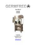
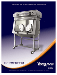
Esco Hospital Pharmacy Isolator – Negative Pressure, Recirculating (HPI-6N_)
Section I: General Requirements
1. The isolator shall meet the performance requirements of the following:
a. CETA CAG-001-2005 (USA)
b. CETA CAG-002-2006 (USA
c. USP CHAPTER 797 (USA)
2. The isolator shall comply with the following international air cleanliness standards:
a. ISO Class 3 as per ISO14644-1 (equivalent to Class 1 per US Federal Standard 209E)
b. JIS Class 3 as per JIS B9920 (Japan)
3. The isolator shall provide a sterile negative pressure work environment for the compounding of hazardous materials, antineoplastic, or cytotoxic compounding applications. It shall also provide a more inherently superior sterility compared to open front clean air devices such as laminar flow clean benches and biological safety cabinets. The isolator shall possess the following features for the purpose of maximum patient protection and sterility:
a. A combination of downflow and exhaust ULPA filters to provide a fully integrated envelope for product protection in all configurations
b. ULPA filters with a typical efficiency of 99.999% at 0.1 to 0.3 microns provide superior ISO Class 3 air cleanliness
c. Laminar (unidirectional) airflow within work zone and pass-thru to enable recovery of chamber atmosphere to ISO Class 3 conditions within 3 minutes following a worse-case contamination event
d. Airlock pass-thru to ensure work zone remains sterile during insertion and removal of items
e. Safe glove changing process with zero risk of contamination.
4. The isolator shall meet or exceed all applicable safety requirements and also be designed to protect the product within from airborne contaminants. Work zone and pass-thru shall be under negative pressure to the room in order to maintain operator protection in case of a breach in the barrier isolation system.
5. The manufacturer shall individually test every isolator before shipment. A test report shall be provided to the customer with a duplicate copy permanently attached to the isolator. At a minimum, the following tests shall be performed:
a.
b.
c.
d.
e.
f.
g.
h.
Filter Leak
Downflow Velocity
Dynamic Pressure
Particle Count or Air Cleanliness
Product Ingress and Egress
Recovery Time
Gauntlet Breach
Operator Comfort (include noise, light and vibration)
6. On request, a representative of the purchaser may witness all tests via a “Factory Acceptance Testing” program. Charge applies.
7. All 230VAC 50HZ models shall be CE marked.
8. The manufacturer must have a quality management system that is certified to ISO 9001, and an environmental management system that is certified to ISO 14001.
:
Global Offices
Singapore | Philadelphia, USA | Leiden, The Netherlands | Salisbury, UK
Kuala Lumpur, Malaysia | Beijing, Shanghai & Guangzhou, China | Mumbai, India | Manama, Bahrain
Worldwide Headquarters • Esco Micro Pte Ltd • 21 Changi South Street 1 • Singapore 486777
Phone +65 6542 0833 • Fax +65 6542 6920 • [email protected] • www.escoglobal.com
ROC No. 198400165W
Section II: Filtration System
1. The isolator shall be equipped with the following particulate filters:
a. One supply filter to provides clean air to the work surface in a gentle vertical laminar flow
b. One intake filter to ensure ensure recirculation of clean air in work chamber
c. One exhaust filter to exhaust air for preventing heat build-up
2. The intake, supply and exhaust filters shall fulfill the following characteristics:
a.
b.
c.
d.
e.
f.
ULPA (Ultra Low Penetration Air) type (HEPA filters shall not be used)
Mini-pleat separator technique (Aluminum separators shall not be used)
Lightweight aluminum framed (particle board/ wood frame filters shall not be used)
Typical efficiency of 99.999% at 0.1 to 0.3 microns
Protected by a face guard
Test for leaks at time of manufacture
3. The filters shall be easily accessible for scan-testing in the field without accessing any potentially contaminated areas.
4. A dedicated upstream sampling port shall be provided, accessible from within the isolator, to facilitate filter scantesting in the field. Sampling ports accessible from outside the isolator which may lead to environmental contamination in case seals fail, are not acceptable.
5. The downflow filter shall be angled (matching the slope of the isolator main body), so as to increase airflow uniformity over the work zone.
Global Offices | Kuala Lumpur, Malaysia | Leiden, The Netherlands | Manama, Bahrain
Mumbai, India | Philadelphia, USA | Salisbury, UK | Shanghai, China | Singapore
Worldwide Headquarters • Esco Micro Pte Ltd • 21 Changi South Street 1 • Singapore 486777
Phone +65 6542 0833 • Fax +65 6542 6920 • [email protected] • www.escoglobal.com
ROC No. 198400165W
Section III: Fan System
1. The isolator shall be equipped with a permanently lubricated, direct-drive, motorized impeller fan with external rotor designs.
2. The motor shall be equipped with integrated blades to narrow profile and to eliminate the need for a motor shaft.
3. All rotating parts of the fan shall be unitized and balanced for smooth, quiet, vibration-free operations.
4. The motor shall be designed for maximum energy efficiency and minimal maintenance. It shall also possess a
compact design and flat profile with a completely integrated assembly to optimized motor cooling.
Global Offices | Kuala Lumpur, Malaysia | Leiden, The Netherlands | Manama, Bahrain
Mumbai, India | Philadelphia, USA | Salisbury, UK | Shanghai, China | Singapore
Worldwide Headquarters • Esco Micro Pte Ltd • 21 Changi South Street 1 • Singapore 486777
Phone +65 6542 0833 • Fax +65 6542 6920 • [email protected] • www.escoglobal.com
ROC No. 198400165W
Section IV: Isolator Control and Alarm System
1. The isolator shall have a microprocessor incorporated to supervise all isolator functions and monitors downflow air, work zone and pass-thru pressures in real-time.
2. The isolator shall be equipped with a soft touch keypad and continuously back-lit LCD (4-line display) for controlling the operation of the fan, light, electrical outlet and microprocessor menu. The LCD shall be able
to display time, main chamber (work zone) pressure, pass-thru pressure, airflow, status messages and to
provide access to Menu function.
3. Airflow shall be measured and displayed with a thermistor-based true velocity airflow sensor mounted on the isolator.
4. An optional (audible and visual) alarm package shall be available on request for monitoring for any unsafe conditions (airflow, window position, and hardware errors).
5. The microprocessor shall be incorporated with the following functions:
a.
b.
c.
d.
e.
Clock/time setting that will not be lost even when the isolator has been switched off
Warm up timer to set time for stabilizing the sensors, fan and control system
Post purge time to set time for purging all residual contaminants in the work zone
Inner door timeout to ensure the inner door has not been left opened for more than a certain period
Measurement unit selection between English and Metric
6. The microprocessor shall enable restrict access to the main menu with password-protected administration. Such restriction shall have control over the fan, blower hour meter, and resetting of default values for parameters such as warm up period, post purge period, PIN for administration and Pin for fan control.
7. It shall be possible for the microprocessor to be set in Maintenance mode for the following purposes:
a. Calibration/Performance validation
b. Filter scanning
c. Checking of input/output diagnostics
Global Offices | Kuala Lumpur, Malaysia | Leiden, The Netherlands | Manama, Bahrain
Mumbai, India | Philadelphia, USA | Salisbury, UK | Shanghai, China | Singapore
Worldwide Headquarters • Esco Micro Pte Ltd • 21 Changi South Street 1 • Singapore 486777
Phone +65 6542 0833 • Fax +65 6542 6920 • [email protected] • www.escoglobal.com
ROC No. 198400165W
Section V: Safety Features
1. All panels leading to potentially contaminated and / or dangerous areas shall be colour coded red. Warning labels alone shall not be acceptable.
2. The blower plenum shall be a permanent design constructed of steel. Cloth or bag based plenums, which are subject to mechanical failure, shall not be used.
3. A removable, perforated metal face guard shall be installed below the downflow filter to ensure airflow uniformity inside the work zone as well as provide secondary protection against damage.
4. The isolator shall possess a robust dual-wall construction. All positive pressure work zones shall be surrounded by negative pressure plenums at the sides and back.
5. All components, with the exception of the fan and filters, shall be located outside of plenum to facilitate service work without the need to decontaminate the isolator.
6. The isolator shall be permanently marked with safety instructions clearly visible from the front.
7. All electrical components shall be UL listed or recognized or certified to any other accepted international standard.
8. The isolator shall meet UL 61010-1/IEC 610101-1, EN 61010-1 and CSA C22.2 No.61010-1.
9. The isolator shall be designed to eliminate sharp edges, protrusions in order to minimize the risk of personal harm to the operator. All metal edges shall be dressed and deburred.
10. High quality and durable hypalon sleeves shall be provided together with safe-change cuff ring that will ensure glove change with zero risk of contamination.
11. All exterior painted surfaces of the isolator shall be powder-coated with an antimicrobial inhibitor to minimize
contamination, which cannot be washed out or diminish by repeated cleaning.
Global Offices | Kuala Lumpur, Malaysia | Leiden, The Netherlands | Manama, Bahrain
Mumbai, India | Philadelphia, USA | Salisbury, UK | Shanghai, China | Singapore
Worldwide Headquarters • Esco Micro Pte Ltd • 21 Changi South Street 1 • Singapore 486777
Phone +65 6542 0833 • Fax +65 6542 6920 • [email protected] • www.escoglobal.com
ROC No. 198400165W
Section VI: General Construction / User Features
1. The isolator shall have the following dimensions:
Dimensions
Exterior (without base stand)
Main chamber (work zone)
Pass through
6ft / 1.8m Isolator
1950 x 820 x 1320 mm (76.8” x 32.3” x 51.9”)
1145 x 610 x 670 mm (45.0” x 24.0” x 26.4”)
355 x 610 x 670 mm (13.9” x 24.0” x 26.4”)
2. The isolator shall be equipped with 2 electrical outlets, mounted on the right hand rear wall. For 115VAC 60HZ
isolator these outlet(s) shall be GFCIs (conventional non-GFCI outlets are not acceptable for safety reasons).
3. The main body of the isolator shall be constructed with 1.2mm (0.05”) 18 gauge electro-galvanized steel with ovenbaked epoxy antimicrobial powder-coated finish
4. Abrasion and corrosion resistant pharmaceutical-grade 304 stainless steel shall be used for the back / side walls, work surface, and drain spillage trough in the isolator. Other grades (which may possess inferior corrosion resistance properties) shall not be acceptable.
5. The internal work zone liner (side and back walls) shall be constructed of a single piece of stainless steel, with large radius corners for easy cleaning. Three-piece construction (left side wall, back wall, right side wall) shall not be acceptable as joints are difficult to clean.
6. The work surface shall be constructed of a single piece of stainless steel for easy cleaning, with raised edges on all sides to contain spillages. Flat or perforated work surfaces are not acceptable.
7. The drain pan (located below the work surface) shall have wide, open corner radii. The four sides of the drain
pan shall also be angled towards the center of the isolator. The left and right side of the drain pan shall be directly sealed to the work zone liner to close off the potentially contaminated space behind the side wall. Alternative designs, which exhibit poor cleanability, shall not be acceptable.
8. The back return air grille shall be integrated with the back wall, to ensure maximum usable working space. With the exception of the front air grille, there shall be no other air slots / perforations on the work surface.
9. All welds shall be ground flush and smooth. There shall be no welded joints to collect contaminants or rust.
10. It shall be possible to clean all areas of the isolator, including behind the front window, without any disassembly.
11. The manufacturer shall be able to provide evidence that all surfaces, joints and welds have been type-tested for cleanability.
12. The manufacturer shall be able to provide evidence that the isolator can be decontaminated using a gas-
phase agent such as formaldehyde and hydrogen peroxide.
13. A comprehensive user and service manual shall be provided with the isolator.
Global Offices | Kuala Lumpur, Malaysia | Leiden, The Netherlands | Manama, Bahrain
Mumbai, India | Philadelphia, USA | Salisbury, UK | Shanghai, China | Singapore
Worldwide Headquarters • Esco Micro Pte Ltd • 21 Changi South Street 1 • Singapore 486777
Phone +65 6542 0833 • Fax +65 6542 6920 • [email protected] • www.escoglobal.com
ROC No. 198400165W
Section VII: Ergonomics
1. The isolator shall be designed with a sloped front to reduce glare, increase accessibility, and ensure a comfortable work position for the operator.
2. The isolator shall possess a sliding tray to facilitate material transfer without the operator having to reach into the passthru interchange area.
5. Each isolator shall be delivered with the following:
a. Tool kit containing common hand tools as well as replacement fasteners and miscellaneous hardware
b. Original factory test report*
c. 1 copy of the User and Service Manual
*The factory test report shall be permanently and digitally archived by the manufacturer should it need to be obtained in the future in the field for isolator re-certification.
6. Quick-start, flicker-free, low-glare, electronically ballasted lightning shall be provided in the isolator. The minimum average light level shall not be lower than 950 Lux to the work surface. The colour of the lighting
shall be warm (5000k fluorescent lamps to be used). Conventional electromagnetic ballasts shall not be acceptable as they exhibit poor energy efficiency and high heat dissipation characteristics.
7. The touch control keypad and isolator LCD display shall be mounted in the centre, and sloped downwards. Alternative designs, which may not be clearly visible from a seated position, shall not be acceptable.
8. Unlike conventional circular ports, the gloveports shall be oval shaped to provide maximum comfort to the operator. The operator shall be able to use the gloves of his/her preference.
9. Optional hydraulic stand shall be available on request for enabling operating to adjust the work surface height to his/her height, for both sitting and standing operation.
Global Offices | Kuala Lumpur, Malaysia | Leiden, The Netherlands | Manama, Bahrain
Mumbai, India | Philadelphia, USA | Salisbury, UK | Shanghai, China | Singapore
Worldwide Headquarters • Esco Micro Pte Ltd • 21 Changi South Street 1 • Singapore 486777
Phone +65 6542 0833 • Fax +65 6542 6920 • [email protected] • www.escoglobal.com
ROC No. 198400165W
Section VIII: Installation and Service
1. It shall be possible to lift the isolator directly off the pallet from the truck onto the support stand (if ordered).
2. The depth of the isolator shall be under 850mm without any disassembly, to enable it to pass through narrow
spaces.
3. The electrical circuit diagram as well as original factory test report shall be permanently attached to the isolator, in addition to a summary of the service instructions.
4. The distributor and / or manufacturer shall be able, on request, to provide local on-site training for the user(s). The manufacturer shall have officially trained the distributor.
5. The distributor shall be able, on request, to certify the isolator on-site after installation. The distributor may also engage or refer the customer to a third-party service provider. The following tests, at a minimum, shall be performed after installation:
a. Downflow velocity and uniformity
b. Airflow visualization
c. Filter leak scan (both downflow and exhaust filters)
Warning: It is the responsibility of the user to ensure the isolator is tested after installation, in order to ensure all the safety requirements have been met.
6. The manufacturer shall provide a minimum parts warranty of 3 years, supported by the local distributor, for the
isolator with the exception of consumable items (filters, lamps etc.)
7. When necessary, the isolator may be installed with:
a.
b.
c.
d.
e.
f.
g.
h.
i.
j.
6-hook IV bar
2 electrical outlets
All stainless steel construction
Sharps disposal system
Cleaning accessories
Alarm package
Support stand of fixed height with leveling feet or casters
Support stand of telescoping height for leaving feet and casters
Adjustable hydraulic stand with casters
Exhaust activated carbon filter and/or external vent system
8. The isolator shall be designed such that all service work may be carried out from the front and top, enabling the isolator to be installed next to a wall or other equipment in order to save room space.
9. The front hinged panel of the isolator shall be equipped with gas spring supports. The front hinged panel shall be secured to prevent accidental access.
10. All service work (excluding installation work) shall be possible with no more than 1 serviceperson (for a 4ft / 1.2m isolator). The fan plenum shall be equipped with mechanical assisted lifting provisions to allow for easy
filter replacement.
Global Offices | Kuala Lumpur, Malaysia | Leiden, The Netherlands | Manama, Bahrain
Mumbai, India | Philadelphia, USA | Salisbury, UK | Shanghai, China | Singapore
Worldwide Headquarters • Esco Micro Pte Ltd • 21 Changi South Street 1 • Singapore 486777
Phone +65 6542 0833 • Fax +65 6542 6920 • [email protected] • www.escoglobal.com
ROC No. 198400165W
Section IX: Site Requirements (Location)
1. The isolator shall be installed as far away as the laboratory space allows from:
a. Personnel traffic flows
b. Air vents (out)
c. Door and Window
d. Any other sources of disruptive air currents or air drafts
As the isolator is fully enclosed, the location and disruptive air currents will not affect performance as much, however it may affect the process of work product movement in and out of the isolator. Placing the isolator away from disruptive air currents will assure maximum CSP sterility.
2. Sufficient clearance of 40 cm (minimum) is recommended between the highest point of the isolator and the ceiling. If the distance is less than 40 cm, the airflow alarm system may require calibration. Exhaust filter area especially susceptible to disruptive air currents or air drafts.
3. For purposes of exhaust filter leak scanning, a minimum distance of 50 cm between the highest point of the isolator and the ceiling is recommended.
4. Adequate space is to be allocated for cleaning behind the isolator and for performing decontamination procedure.
5. A far away position from any source of heat sources (heaters, fan converters, etc.) for optimum operating conditions.
Global Offices | Kuala Lumpur, Malaysia | Leiden, The Netherlands | Manama, Bahrain
Mumbai, India | Philadelphia, USA | Salisbury, UK | Shanghai, China | Singapore
Worldwide Headquarters • Esco Micro Pte Ltd • 21 Changi South Street 1 • Singapore 486777
Phone +65 6542 0833 • Fax +65 6542 6920 • [email protected] • www.escoglobal.com
ROC No. 198400165W
Section X: Site Requirements (Environmental and Electrical Conditions)
This isolator shall be designed for operation under the following environment and electrical conditions:
1. Indoor use
2. Altitudes up to 2000 meters or 6600 ft
3. 20% - 60% relative humidity
4. Temperature range from 20 deg C to 30 deg C (68 deg F to 86 deg F). The temperature in the laboratory is to be maintained within +/-2 deg C under all conditions.
5. Main supply voltage fluctuations not to exceed +/- 10% of the nominal voltage. It is recommended that the voltage fluctuation doesn’t exceed +/- 2% of the nominal voltage at all times.
6. Installation Category: 2.0
Installation category (over-voltage category) defines the level of transient over-voltage which the instrument is
designed to withstand safely. It depends on the nature of the electricity supply and its over-voltage protection means. For example, in CAT II, which is the category used for instruments in installations supplied from
a supply comparable to public mains such as hospital and research laboratories and most industrial laboratories, the expected transient over-voltage is 2500 V for a 230 V supply and 1500 V for a 120 V supply.
7. Pollution Degree: 2.0
Pollution degree describes the amount of conductive pollution present in the operating environment. Pollution degree 2 assumes that normally only
Global Offices | Kuala Lumpur, Malaysia | Leiden, The Netherlands | Manama, Bahrain
Mumbai, India | Philadelphia, USA | Salisbury, UK | Shanghai, China | Singapore


