1
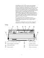
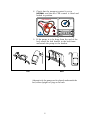
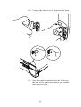
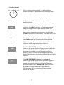
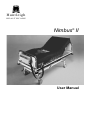
Huntleigh
H E A LT H C A R E
Nimbus II
®
User Manual
CONTENTS
Introduction . . . . . . . . . . . . . . . . . . . . . . . . . . . . . . . . . . . . . 1
About This Manual . . . . . . . . . . . . . . . . . . . . . . . . . . . . . . . 1
About Nimbus II . . . . . . . . . . . . . . . . . . . . . . . . . . . . . . . . . 2
Clinical Applications
Indications. . . .
Contraindications
Patient Transport
Patient In Chair .
.
.
.
.
.
.
.
.
.
.
.
.
.
.
.
.
.
.
.
.
.
.
.
.
.
.
.
.
.
.
.
.
.
.
.
.
.
.
.
.
.
.
.
.
.
.
.
.
.
.
.
.
.
.
.
.
.
.
.
.
.
.
.
.
.
.
.
.
.
.
.
.
.
.
.
.
.
.
.
.
.
.
.
.
.
.
.
.
.
.
.
.
.
.
.
.
.
.
.
.
.
.
.
.
.
.
.
.
.
.
.
.
.
.
.
.
.
.
.
.
.
.
.
.
.
.
.
.
.
.
.
.
.
.
.
.
.
.
.
.
.
.
.
.
.
.
.
.
.
.
.
.
.
.
.
.
.
.
.
.
3
3
3
3
3
Product Description .
Mattress . . . . .
Pump . . . . . .
Bed Bracket . . .
Tube-Set . . . .
.
.
.
.
.
.
.
.
.
.
.
.
.
.
.
.
.
.
.
.
.
.
.
.
.
.
.
.
.
.
.
.
.
.
.
.
.
.
.
.
.
.
.
.
.
.
.
.
.
.
.
.
.
.
.
.
.
.
.
.
.
.
.
.
.
.
.
.
.
.
.
.
.
.
.
.
.
.
.
.
.
.
.
.
.
.
.
.
.
.
.
.
.
.
.
.
.
.
.
.
.
.
.
.
.
.
.
.
.
.
.
.
.
.
.
.
.
.
.
.
.
.
.
.
.
.
.
.
.
.
.
.
.
.
.
.
.
.
.
.
.
.
.
.
.
.
.
.
.
.
.
.
.
.
.
.
.
.
.
.
4
4
5
6
6
Installation . . . . . . . . . . . . . . . . . . . . . . . . . . . . . . . . . . . . . . 7
Preparing the Mattress and Pump . . . . . . . . . . . . . . . . . . . . . . . 7
Inflating The Mattress . . . . . . . . . . . . . . . . . . . . . . . . . . . . . 11
Testing The Power Fail Alarm . . . . . . . . . . . . . . . . . . . . . . . . . 11
Operation . . . . . . . . . . . . . . . . . . . . .
System Optimisation . . . . . . . . . . . . .
Selecting Mode Of Operation . . . . . . . .
Silencing Audible Alarms . . . . . . . . . .
Comfort Control . . . . . . . . . . . . . . .
Transport Control . . . . . . . . . . . . . .
CPR Control . . . . . . . . . . . . . . . . .
Controls, Indicators And Alarms - Pump Unit
.
.
.
.
.
.
.
.
.
.
.
.
.
.
.
.
.
.
.
.
.
.
.
.
.
.
.
.
.
.
.
.
.
.
.
.
.
.
.
.
.
.
.
.
.
.
.
.
.
.
.
.
.
.
.
.
.
.
.
.
.
.
.
.
.
.
.
.
.
.
.
.
.
.
.
.
.
.
.
.
.
.
.
.
.
.
.
.
.
.
.
.
.
.
.
.
.
.
.
.
.
.
.
.
.
.
.
.
.
.
.
.
.
.
.
.
.
.
.
.
.
.
.
.
.
.
.
.
.
.
.
.
.
.
.
.
13
13
13
14
14
14
15
16
Cleaning . . . . . . . . . . .
During Use . . . . . . . .
Laundering . . . . . . . .
Mattress Cover. . . . . .
Foam Layer . . . . . . .
Mattress Base And Cells.
Nimbus II Pump . . . . .
.
.
.
.
.
.
.
.
.
.
.
.
.
.
.
.
.
.
.
.
.
.
.
.
.
.
.
.
.
.
.
.
.
.
.
.
.
.
.
.
.
.
.
.
.
.
.
.
.
.
.
.
.
.
.
.
.
.
.
.
.
.
.
.
.
.
.
.
.
.
.
.
.
.
.
.
.
.
.
.
.
.
.
.
.
.
.
.
.
.
.
.
.
.
.
.
.
.
.
.
.
.
.
.
.
.
.
.
.
.
.
.
.
.
.
.
.
.
.
20
20
20
20
21
21
22
.
.
.
.
.
.
.
.
.
.
.
.
.
.
.
.
.
.
.
.
.
.
.
.
.
.
.
.
.
.
.
.
.
.
.
.
.
.
.
.
.
.
.
.
.
.
.
.
.
.
.
.
.
.
.
.
.
.
.
.
.
.
.
.
.
.
.
.
.
.
Troubleshooting . . . . . . . . . . . . . . . . . . . . . . . . . . . . . . . . . . 23
Fuse Replacement. . . . . . . . . . . . . . . . . . . . . . . . . . . . . . . 24
Warranty And Service . . . . . . . . . . . . . . . . . . . . . . . . . . . . . . . 25
Routine Checks . . . . . . . . . . . . . . . . . . . . . . . . . . . . . . . . . . 26
Mattress . . . . . . . . . . . . . . . . . . . . . . . . . . . . . . . . . . . . 26
Pump. . . . . . . . . . . . . . . . . . . . . . . . . . . . . . . . . . . . . . 26
Technical Description . . . . . . . . . . . . . . . . . . . . . . . . . . . . . . . 27
(i)
Safety
Before you connect the system pump to a mains socket, read carefully all the
installation instructions in Section 4 – Installation.
The system has been designed to comply with regulatory safety standards
including:
• EN 60601-1
For your own safety and the safety of the equipment always take the following
precautions:
• Keep the pump away from sources of liquids
• Do not expose the system, especially the mattress, to naked flames, such
as cigarettes etc.
• Do not store the system in direct sunlight
• Do not use hypercarbonate and phenolic based cleaning solutions
• Keep sharp objects away from the mattress
• Ensure that the system is clean and dry prior to storage
• Store the pump and mattress in the protective bags supplied
• We recommend the use of cot sides on the bed while the system is in use
and the patient is positioned on top. Local policies regarding the use of
cot sides should be taken into account.
• Keep these instructions handy for reference
(ii)
SAFETY WARNING
The cover of this product is vapour permeable but not air
permeable and may present a suffocation risk. It is the
responsibility of the care giver to ensure that the user can use
this product safely.
WARNINGS
Electrical equipment may be hazardous if misused. The pump’s
case back should only be removed by authorised technical
personnel.
Do not use the Nimbus II pump in the presence of flammable
gases such as anaesthetic agents.
Caution
Handles are provided for lifting the mattress complete with
patient from the bed frame. The drag handles are provided
ONLY for transporting the mattress and patient across flat
surfaces in an emergency and should NOT be used for any other
purpose.
(iii)
(iv)
1. Introduction
About
This Manual
This manual is your introduction to the Nimbus® II
system. Use it to initially set up the mattress
replacement system, keep it as a reference for
day-to-day routines and as a guide to maintenance.
Section 2
Clinical Applications: gives examples of
Section 3
Product Description: a technical
description of the system.
Section 4
Installation: explains how to install and set
up the Nimbus II system.
Section 5
Operation: a reference guide for
Section 6
Cleaning: routine cleaning in use and
Section 7
Troubleshooting: routine maintenance
the type of patients that could benefit from
this system and illustrates a method of
assessing them.
day-to-day operation and contains
important information on what to do if the
patient suffers a cardiac arrest.
recommended laundering procedures.
procedures and solutions for minor
problems that may occur.
Section 8
Warranty and Service: details the warranty
and what to do if the equipment requires
servicing or repair.
Section 9
Routine Checks: details periodic
inspections of the pump and mattress.
Section 10 Technical Description: a list of technical
data.
1
About Nimbus II
Nimbus® II is a Dynamic Flotation System for the
prevention, treatment and management of pressure
sores. It employs a revolutionary cell design to realise
interface pressures below 20 mmHg for over 65% of
the cycle.
The Nimbus II system incorporates a unique sensor
pad, known as Auto-Matt®, which ensures that the
patient is automatically supported at optimum
pressures regardless of size, height, position or weight
distribution.
The Nimbus II mattress is designed for use with
standard hospital beds as well as in the home. Users
are able to employ established practices for lifting,
turning and moving patients. Beds can also be
adjusted or gatched in the normal way without
impairing the mattress pressure relieving performance.
A water resistant, vapour permeable cover is supplied
that enhances patient comfort whilst protecting the
mattress interior from contamination. It is simple to
clean in situ but can also be quickly unzipped and
totally removed for laundering, gas sterilisation or
autoclaving.
If cardiac arrest occurs the mattress can be deflated in
less than 10 seconds to allow cardiac resuscitation
procedures to be performed.
The pump provides two modes of operation:
l
l
A dynamic mode that cycles the support
surface beneath the patient every 10 minutes
providing periods of pressure relief for the
whole body
A static mode where the support surface
remains constant (all cells equally inflated)
2
2. Clinical Applications
The Nimbus II system, with its ability to provide reduced interface pressures in
both dynamic and static operating modes, is used to treat those patients who are
at very high risk of developing or who have pressure ulcers.
A risk assessment tool combined with clinical judgement should be used when
determining a patient’s level of risk of developing pressure ulcers. Patient risk
assessment should be an ongoing process as changes in the patient’s condition
may increase or decrease their risk level.
Indications
The Nimbus II system is appropriate for patients
assessed to be at very high risk of developing pressure
ulcers, and for all grades of pressure ulcer up to and
including grade 4 (NPUAP, 1989)1.
The Nimbus II system should be used in dynamic mode
whenever possible as this will continuously change the
tissue pressure points, providing the highest degree of
pressure relief. Nimbus II in static mode provides a
stable surface for nursing procedures and for patients
with spinal alignment problems. Both modes of
operation are appropriate for use for patients weighing
between 45-250 kg (100-550 lb).
Contraindications
The Nimbus II system should not be used for patients
with unstable spinal fractures.
In the case of patients with other unstable fractures,
where a moving surface could be harmful, advice
should be obtained from the appropriate physician
before using the Nimbus II system.
Patient Transport
Patients should be transported on the Nimbus II system
whenever they leave the nursing unit. Refer to the
section in this manual dealing with operation of the
transport function.
Patient In Chair
If the patient will be sitting in a chair for any period of
time, it is strongly recommended that a pressure
reducing or relieving seat cushion is used.
+
The Nimbus II system is an aid to the prevention and
management of pressure ulcers. If there is no improvement in
the patient’s condition, specialist advice should be sought.
The above are guidelines only and should not replace clinical
judgement or experience
1
National Pressure Ulcer Advisory Panel (1989). Clinical Practice Guideline, Number 3,
AHCPR, US Department of Health & Human Services, 1992.
3
3. Product Description
Mattress
The Nimbus II mattress is constructed from several
materials and composites, most of which contain
polyurethane (P.U.). This material is noted for its
excellent durability coupled with good flexibility. This
flexibility does not significantly alter in long term use
and thus mattress components do not suffer the effects
of ‘age hardening’.
The mattress is totally enclosed in a carefully designed
double zipped cover. The top and sides of the cover are
constructed from a two-way super stretch and moisture
proof material which is vapour permeable for
maximum patient comfort. The base of the cover is
constructed from a tough abrasion resistant material
and is fitted with bed attachment straps, sheet clips
lifting and drag handles.
Patient support is provided by cells that are grouped in
three sections, each of which has a specific function.
The head cells remain at a constant pressure for pillow
stability and patient comfort. The torso area is served
by special cell assemblies that combine alternating and
static pressure characteristics to support patients fully
in both lying and sitting positions without the risk of
‘bottoming’. The thigh to foot section of the mattress
has cells that dynamically cycle to maximise pressure
relief.
A CPR (Cardio-Pulmonary Resuscitation) control is
positioned at the foot end of the mattress to allow the
air to be evacuated in under 10 seconds should a
cardiac arrest occur.
Transport Control
FAST DEFLATE
NORMAL
CP
R
1
2
3
4
TRANSPORT
Tube Set
Connector Port
Situated next to the CPR control is the Transport
control. This allows cross connection of the cell
structure creating an even pressure in all the cells. The
transport control also seals the mattress so that air is
not exhausted when the tube-set is disconnected. This
feature is extremely useful for transporting the patient
between wards, to operating rooms and X-ray
departments without removing the patient from the
bed. A further application of the transport feature is
that, during a power failure, prompt operation of the
transport control will seal the mattress and maintain
support for at least 12 hours.
The mattress has been designed for ease of
maintenance. The top cover can be removed and
replaced with the patient in situ so that it can be
laundered.
All mattress components can be easily changed if
damage occurs, either as unit parts or assemblies.
Pump
À
Á
Æ
À
Á
Â
Ã
Ã
Â
Ä
Å
Ç
ADVANCED DYNAMIC FLOTATION SYSTEM
Ä
Å
Æ
Ç
Power (and Alarm reset) switch
Static/Dynamic push button
Mute push button
Alarm symbol
5
Alarm messages
Comfort control
Mains input connector
Tube set connector
The pump comprises a rugged moulded case with non
slip feet on the base and rear and an integral carry
handle.
The unit has been designed to maintain sustained
operation and to withstand prolonged use in the
hospital environment .
The controls and indicators are located on the front
panel which is recessed to prevent accidental
operation.
The pump incorporates a sophisticated alarm system
which differentiates between normal operation and
genuine system faults. If an alarm situation is detected
a flashing indicator will illuminate together with an
indication of the cause of alarm and an audible
warning will sound.
Bed Bracket
The pump can be fixed to the foot end of a hospital
bed by the separate bed bracket which has been
designed for simplicity and ease of use. It features a
simple self adjusting mechanism that clips onto most
common bed frames (18-50mm wide) and a hook that
fits into the pump handle.
Once installed, the pump is resistant to being
accidentally dislodged from the end of the bed.
The pump can also be stood on the floor, either
vertically or horizontally.
Tube-Set
The tube-set incorporates a flexible, compact anti-kink
tube that is resistant to crushing and any subsequent
obstruction of air flow. Each end has a quick lock
system for easily connecting and disconnecting the air
supply at the pump and mattress.
6
4. Installation
These instructions cover initial set up and operation of the Nimbus II system.
More detailed information regarding controls, alarms and indicators can be
found in Section 5.
Preparing the
Mattress and Pump
1. Remove mattress, pump and tube set from the
packaging. You should have the following
items:
l
l
l
l
l
mattress assembly including the
Soiled/Available For Use label
pump
power cord
bed bracket
tube-set
2. Store the pump box and carry bag in a safe
place for future use.
3. Remove the conventional mattress from the bed
frame and check that there are no protruding
springs or sharp objects on the bed base.
+
Heavily ridged bed baseboards may require special
considerations for correct system operation – consult your
Huntleigh Healthcare service engineer.
4. Unroll the mattress onto the bed base from the
head end ensuring that the CPR swing label is
hanging freely.
5. Attach the mattress to the bed frame using the
hook and loop fastener straps.
7
+
If the bed is to be gatched, attach the mattress to the movable
part of the bed only.
6. Unzip the mattress cover to locate the
Auto-Matt sensor pad which is situated under
the cells between the soft and compressed base
foam. Ensure that the Auto-Matt pad is lying
flat and not kinked.
Leave the mattress cover end free when
gatching the bed.
Cover
FA
ST
C
P
R
DEF
LA
TE
NO
RM
TR
Air Cells
AL
AN
SIT
Foam Layer
Auto-Matt Pad
6
4
7. Zip up the mattress taking care not to trap any
cell material in the zip.
8
8. Check that the transport control is set to
NORMAL and that the CPR control is fitted and
locked in position.
FAST DEFLATE
NORMAL
CP
R
1
TRANSPORT
2
3
9. If the pump is to be hung from the end of the
bed, attach the bed bracket to the bed frame
and attach the pump to the bracket.
Old
New
Alternatively the pump can be placed underneath the
bed, either upright or lying on its back.
9
10. Connect the tube-set to the mattress and pump,
ensure both connections are secure.
11. Insert the mains connector into the socket on
the side of the pump and connect to a suitable
mains power outlet.
10
Inflating
The Mattress
1. Switch the pump On/Off switch to ON: the ON
light on the front panel should illuminate.
2. The pump will now run a self test for
approximately 3 seconds when all indicators
will be illuminated.
3. If the pump detects low pressure it will enter
an inflation sequence with the LOW PRESSURE
and WAIT messages illuminated.
Once normal operating pressure has been reached both
the LOW PRESSURE and WAIT lights will switch off.
It may take 15 minutes to inflate the mattress.
Testing The
Power Fail Alarm
The power fail alarm is powered by a rechargeable
battery.
The duration of the alarm will depend on the level of
charge in the battery.
In use, it may have become discharged or reached the
end of its life. It is therefore recommended that the
alarm be tested before use.
1. Connect the pump to the mains, switch on and
allow to run for 10-15 seconds.
2. Remove the mains power at the wall socket
without switching the pump off.
3. The alarm should operate within 10 seconds.
Caution
If the power fail alarm does not operate after this test, only use
the pump under supervision to ensure that the power-on status
is checked at regular intervals.
4. If the alarm does not operate, run the pump for
4 hours to recharge the battery.
5. Retest the alarm after at least 4 hours. Allow
the alarm to operate for 2 minutes to ensure
that it has been adequately recharged.
6. If the alarm does not operate for 2 minutes,
call the service engineer.
11
Continue to use the pump only under supervision to
ensure that the power-on status is checked at regular
intervals.
All other alarms will continue to function as
normal.
+
When rolling up the mattress after a period of use,
always roll from the foot end.
Complete and return the Guarantee Registration
Card.
12
5. Operation
These instructions cover day-to-day operation of the system. Other operations,
such as maintenance and repair, should only be carried out by suitably qualified
personnel.
System
Optimisation
The Nimbus II system automatically compensates for
patient weight distribution and position optimising the
pressure relieving performance. To ensure that the
pressure relieving properties are not impaired, the
cover must not be pulled tight and covering sheets
should fit loosely using the attached clips.
The system provides two modes of operation: Static
and Dynamic. Dynamic provides the optimum
pressure relieving performance and should be used in
most cases. Static mode provides a stable, non-moving
support surface for instances where a dynamic support
surface is contra-indicated.
Selecting Mode
Of Operation
+
In Dynamic mode the support surface beneath the
patient is cycled every 10 minutes. In Static mode the
support surface remains constant (all cells equally
inflated). When Static mode is selected an indicator
on the static push button illuminates. Both modes of
operation are selected by this push button.
The pump defaults to Dynamic mode of operation when switched
on at the pump.
To change mode of operation:
1. Press the static push button once. An audible
tone will sound and a visual indicator on the
push button will illuminate to show that the
system is in static mode
2. To select Dynamic mode from Static mode
press the static push button once. An audible
tone will sound and the visual indicator will
switch off
13
Silencing
Audible Alarms
+
In its normal operating mode an audible alarm can only be
silenced after an alarm has occurred. An internal setting can be
used to change the mode of operation so that this button can
pre-silence an alarm. Call your service engineer if this option is
required.
Comfort Control
+
Audible alarms can be silenced using the mute push
button. To silence an alarm simply push the mute
button once (the mute light will remain on).
Mattress cell pressure can be manually adjusted for
patient comfort using the rotary comfort control. Turn
clockwise for a firmer setting and anti-clockwise for a
softer setting – the mattress minimum pressure is
maintained at the chosen level.
The system automatically compensates for patient size, height,
position and weight distribution to provide optimum support
regardless of comfort control setting.
Transport Control
This seals the mattress and allows removal of the
pump for patient transport. The patient will remain
supported by the mattress for at least 12 hours in
transport mode.
1. At the foot end of the mattress turn the
transport control knob clockwise to
TRANSPORT.
2. Turn the pump off and disconnect the tube-set.
+
If the transport control is set to TRANSPORT with the tubeset
connected and pump on, then the pump will indicate a low
pressure fault alarm.
To resume normal operation simply re-connect the
pump and turn the transport control knob
anti-clockwise to NORMAL.
14
CPR Control
IMPORTANT
IN THE EVENT OF CARDIAC ARREST.
In the event of a patient suffering cardiac arrest:
1. Lift red handle on control panel at foot end of
mattress.
2. Turn handle anti-clockwise.
3. Pull handle away from panel.
15
4. The triangular seal will rotate and air exhaust
from the mattress. The torso area of the patient
will bottom out in less than 10 seconds.
FAST DEFLATE
NORMAL
CP
R
1
TRANSPORT
2
3
To Re-set
1. Turn grey triangular seal clockwise and push
onto connectors
2. Turn red handle clockwise
3. Fold handle flat to lock in position
Controls, Indicators And Alarms - Pump Unit
Controls
On/Off Switch
(And Alarm Reset)
Switches the mains power on and off. It is combined
with an internal battery circuit that will activate the
alarm system if the power supply is interrupted prior to
switching off. Examples are mains lead removal,
mains power failure.
O
I
Static
Selects operating mode, switches between either Static
or Dynamic mode. Static mode is confirmed when the
yellow indicator on the push button is illuminated.
When Dynamic mode (default) is selected the yellow
indicator will be extinguished.
Mute
An audible alarm mute is provided to cancel warning
sounds during an alarm condition.
16
Comfort Control
soft
firm
Indicators
‘WAIT
This is a rotary action control to set the relative
firmness/softness of the mattress for patient comfort.
Visible and audible indicators are provided as
described below.
If the pump detects a low pressure in the mattress at
switch on, the WAIT indicator is illuminated and the
pump performs a start up procedure to inflate the
mattress quickly.
Once correct operating pressures have been reached
the WAIT indicator is switched off. This may take up to
15 minutes.
static
The indicator on the static push button is illuminated
when Static mode has been selected for operation.
mute
The indicator on the mute push button is illuminated
when the audible alarm has been silenced.
HIGH
PRESSURE
LOW
PRESSURE
The HIGH PRESSURE indicator is illuminated
whenever the pump detects a high pressure within the
mattress. If this condition occurs the air supply from
the pump is switched off until normal pressure is
detected. After 2 seconds of normal pressure being
detected the indicator is switched off and the air supply
restarted.
The LOW PRESSURE indicator is illuminated
whenever the pump detects a low pressure within the
mattress. This may indicate that there is insufficient
pressure to support a patient or that the Transport
control is turned to the TRANSPORT position whilst
the pump is on and connected to the mattress.
This indicator will be switched off once normal
pressure is reached.
17
U.K. Only
POWER
+
Alarms
Flashing POWER light indicates power has been
interrupted. Steady POWER light indicates power has
been interrupted but has been restored.
This may only be cancelled by turning the On/Off switch off and
on again.
The pump unit incorporates a sophisticated alarm
detection system that differentiates between patient
movement and genuine alarm conditions. Whenever an
alarm occurs a flashing red triangle becomes active
together with an indicator of the cause of the alarm.
Additionally, an audible warning will sound unless
cancelled by the Mute button as described earlier.
The triangular alarm symbol is displayed with one or
more of the following visual indicators:
l
LOW PRESSURE
l
HIGH PRESSURE
l
PUMP FAULT
l
POWER (indicating a power failure)
If any of these alarm conditions is raised the alarm will
be illuminated in red and will flash.
+
Once an alarm has been initiated it can only be cancelled by
switching the pump unit off and then switching back on.
For possible alarm causes, see the table in Section 7.
The telephone symbol illuminates when the pump unit
is ready for service. Huntleigh Healthcare recommends
that maintenance be carried out every 12 months or
whenever the
symbol is illuminated.
+
The pump will continue to function normally even when the
symbol is illuminated.
18
Controls - Mattress Unit
Transport
This sets the mattress into Transport mode where the
support surface is equally pressurised and the pump
and tube-set can be removed. In this mode the mattress
will support the patient for at least 12 hours.
CPR
The CPR deflate control provides a means of rapidly
deflating the mattress to allow normal resuscitation
procedures to be carried out.
+
This control must be used to deflate the mattress for packing and
storage.
19
6. Cleaning
The following guidelines have been established in accordance with infection
control procedures. Should you have any questions regarding cleaning or if you
require further information please contact our Customer Services Department or
your local Huntleigh Healthcare representative.
Caution
Gloves and protective clothing should always be worn when
carrying out cleaning procedures.
During Use
The mattress, pump and tube set should be cleaned
weekly using a damp soft cloth and mild detergent.
The pump can then be wiped with a sodium
hypochlorite solution to a dilution of 1000ppm.
Hypercarbonate and phenolic based cleaning
solutions should never be used.
The mattress cover can be easily unzipped for
complete removal, laundering or sterilisation. The
mattress can be cleaned in the normal way using soap
and water. Heavily soiled mattresses can be cleaned
with a sodium hypochlorite solution to a dilution of
1000ppm before laundering.
Never use Phenol based solutions as these will
damage the surface coating.
If there appears to be staining or body fluids on the
mattress cells they can be treated using a sodium
hypochlorite solution to a dilution of 1000ppm.
The tube-set should be thoroughly cleaned with soap
and water followed by sodium hypochlorite solution to
a dilution of 1000ppm.
Laundering
The laundering process has been compiled to eliminate
the most serious of microbes. The Nimbus II top cover
should be laundered in accordance with washing of
hospital soiled linen procedures.
Temperatures must be maintained at 71° centigrade
(160°F) for a minimum of 3 minutes through the
disinfection stage followed by rinsing and extraction.
Mattress Cover
If the Nimbus II cover is soiled, wash down before
sterilisation.
20
Laundry Washing Cycle
Industrial
Domestic
Break wash
Main wash
Main wash 2
Extraction
3 Cold Rinses
Extraction
Cold
10 minutes
60°C (140°F) 6 minutes
71°C (160°F) 10 minutes
2 minutes
Prewash
Main Wash
Extraction
Cold Rinses
Extraction
Cold
71°C (160°F) 10 minutes
2 minutes
5 minutes
5 minutes
TUMBLE DRYING OR TUNNEL DRYING IS
NOT RECOMMENDED.
Sterilisation
Autoclaving
In the event of contact with infectious microorganisms, the cover can be autoclaved.
Fold the cover with autoclaving paper between the
layers, ensuring that the paper is against the shiny
sides of the cover.
Autoclaving temperature is 134°C (273°F).
Cycle time – 40 minutes (includes 2 minutes
sterilisation and 20 minutes drying time).
Gas Sterilisation
Gas sterilisation is suitable for the complete mattress.
Wash to remove any soiling before sterilisation. The
temperature should not exceed 51°C (125°F).
Foam Layer
The foam protecting the Auto-Matt sensor pad can be
machine washed at temperatures up to 60°C (140°F)
and can be tumble dried.
Mattress Base
And Cells
The base and cells can be wiped over with a solution
of sodium hypochlorite 1000ppm or any other
non-phenolic germicidal solution.
Disinfection
Temperatures must be maintained at 71°C (160°F) for
a minimum of 3 minutes through the disinfection stage
followed by rinsing and spinning.
21
Nimbus II Pump
WARNING
Switch off the electrical supply to the pump and disconnect the
power cord from the mains supply before cleaning and
inspection.
Cleaning
The pump casing is manufactured from plastic and
should be cleaned using a damp soft cloth dampened
with a mild detergent. This can be followed by a
sodium hypochlorite solution to a dilution of
1000ppm.
Do not use abrasive compounds or pads.
General Care,
Maintenance
And Inspection
Check all electrical connections and power cord for
signs of excessive wear.
Test power fail alarm system before use. For
procedure, see Installation section.
In the event of the pump being subjected to abnormal
treatment, e.g. immersed in water or dropped, the unit
must be returned to an authorised service depot.
Maintenance
The equipment has been designed to be virtually
maintenance-free between service periods. It is
recommended the pump be serviced annually by a
Huntleigh Healthcare authorised service agent.
Servicing
Huntleigh Healthcare will make available on request
service manuals, component parts list, and other
information necessary for technical personnel to repair
the system.
22
7. Troubleshooting
The following table provides a troubleshooting guide for the Nimbus II system
in the event of malfunction.
Indicator
Possible Cause
Remedy
LOW PRESSURE
and WAIT
The pump is inflating the
mattress. Both these
indicators will extinguish
when operating pressure is
reached.
LOW PRESSURE
The tube-set is not
connected properly.
Check the tubeset
connectors and ensure they
are properly clipped onto the
pump and mattress
The mattress is set to
TRANSPORT.
Turn the control on the
mattress to NORMAL.
There is a leak in the
system.
Call service engineer.
There is a block in the
tubing.
Check that the tube-set is
not kinked.
HIGH PRESSURE
Check that the Auto-Matt
pad is flat and not kinked.
POWER – flashing
with triangle.
Power has been removed
from the unit.
Re-apply power or switch
the unit off.
If the power failure is
prolonged, switch to
TRANSPORT mode and
disconnect the tubing. The
mattress will remain inflated
for at least 12 hours.
POWER – continuously
illuminated.
A temporary power failure
has occurred in the pump.
Check that the pump is still
in its desired mode of
operation (Static or
Dynamic).
The POWER message may
be cancelled by switching
the unit off and on again.
PUMP FAULT
+
Internal pump malfunction.
Call service engineer.
If the pump has not been used for a number of months, the
battery system which indicates power fail may be discharged.
Run the pump for a few hours and the battery will recharge and
provide power fail alarm indication as normal.
23
Fuse Replacement
If the system fails to operate when plugged in and
switched on, the fuses situated above the mains inlet
socket on the pump should be checked. To do this,
disconnect the pump from the main power supply and
remove fuse holder cap using a suitable screwdriver.
Important
To protect against fire hazard, replace blown fuse with identical
type and rating - 500mA quick blow. If the fuse blows again
contact a service engineer or suitably qualified personnel.
24
8. Warranty And Service
1.
Huntleigh Healthcare guarantees to repair, service, adjust or replace free
of charge equipment which is proved to Huntleigh Healthcare’s satisfaction to
be defective due to defects in material or workmanship if such equipment is
returned to the service address given below, transportation charges prepaid,
within 12 months after the date of purchase by the end user. Huntleigh
Healthcare will provide an extended warranty for two years from the date of
purchase by the end user if preventative maintenance and servicing, to be
carried out only by Huntleigh Healthcare service engineers, is arranged with
effect from the anniversary date of purchase. This extended warranty will be
invalidated if the tamper seal is broken.
2.
Without limitation to the generality of the above or to the requirement
for proof, this warranty excludes:
(i) equipment damaged through shipping, tampering, improper
maintenance, carelessness, accident, negligence or misuse and
(ii) equipment altered, repaired or dismantled other than with the
manufacturer’s written authorisation, using its approved procedures
and by properly qualified and trained technicians
3.
No other warranty, express or implied is given.
4.
In no event shall Huntleigh Healthcare (including any member of the
same group of companies) be liable for any indirect or consequential
damages or losses resulting from the use of equipment.
5.
In no event shall Huntleigh Healthcare’s liability arising from use of the
equipment exceed the purchase price of such equipment.
Nothing in this warranty shall exclude or limit Huntleigh Healthcare’s liability for
death or personal injury resulting from use of defective equipment or due to Huntleigh
Healthcare’s negligence.
For service, maintenance and any questions regarding this, or any other Huntleigh
Healthcare product, please contact:
Huntleigh Healthcare
310 – 312 Dallow Road
Luton Beds LU1 1TD UK
Tel: 01582 413104
Fax: 01582 459100
or your local distributor.
25
9. Routine Checks
Mattress
1.
Remove top cover and inspect for signs of wear or any tears.
2.
Check zips are still operative.
3.
Check integrity of all connectors including cell to manifold and sensor
pad to inlet plate.
4.
Ensure all cell fasteners are snapped to the manifold and are not loose
or faulty.
5.
Check that stitching which secures the drag straps to the base of the
mattress is sound and no fraying has occurred.
Pump
1.
Check the outer casing of the pump unit for damage.
2.
Examine the mains supply lead of the pump unit for signs of
wear/damage, replace if necessary.
3.
Test power fail alarm system before use. For procedure, see
Installation section.
26
10. Technical Description
Pump
Size:
Weight:
Case material:
Supply Voltage:
Electrical Rating:
Fuse rating:
Air inlet filter:
Operating cycle:
Electrical Safety Standards
NB2000/Euro
Length 508 mm (20")
Height 220 mm (8.7")
Depth
100 mm (4")
5.7 kg (12.5 lb)
ABS/polycarbonate alloy
UK – 240 V ac, 50 Hz
Europe – 220 V ac, 50 Hz
30 VA
F 500 mA
Service replaceable
10 minutes
EN60601-1
Degree of protection
against electric shock:
Degree of protection
of ingress of liquids:
Mode of operation:
Symbols
Class I, type BF
Ordinary (not protected)
Continuous
alternating current
O (Off) power disconnection from the mains
supply.
I (On) power connection to the mains
supply.
Type BF
Fuse rated 500 mA
Refer to product manual
Environmental Conditions
Operating
Temperature range:
Relative humidity:
Atmospheric pressure:
+10°C to +40°C
30% to 75%
700hPa to 1060hPa
27
Storage
Storage temperature range:
Relative humidity:
Atmospheric pressure:
Environmental Protection:
Tube Set
Length:
Material
Tube:
Connectors:
Mattress
Size:
Weight:
Cover material:
Base material:
Cell material:
Cleaning Symbols:
-40°C to +70°C
10% to 100% (non-condensing)
500hPa to 1060hPa
Please dispose of this unit in accordance with
local regulations.
1 metre (39.4")
5-way moulded PVC
Moulded nylon
Length
2085mm (82")
Height (at edges) 215 mm (8.5")
Width
890 mm (35")
11.5kg (25lb 5oz)
Polyurethane coated knitted nylon
Polyurethane coated woven nylon
0.3mm (0.012") Polyurethane flexible sheeting
wash at 80°C
do not iron
do not use phenol-based products
do not tumble dry
wipe surface with damp cloth
C
1000ppm
NaOCl
NaDCC
use solution diluted to 1000 ppm
152997EN_01
04/00
28
Huntleigh
152997EN/01
H E A LT H C A R E
Huntleigh Healthcare Ltd. A Huntleigh Technology PLC Company
310-312 Dallow Road, Luton, Bedfordshire, LU1 1TD
Telephone: 01582 413104 Fax: 01582 459100
Sales Enquiries Telephone: 01582 745700 Fax: 01582 745745
Huntleigh Rentals 24 hour Helpline Lo-call 08457 342000
Website: www.huntleigh-healthcare.com E-mail: [email protected]
Abcde
943447
GENLIT004A/01
®
®
A Pyramid of Care Product
® and ™ are trade marks of Huntleigh Technology PLC.
As our policy is one of continuous improvement, we reserve the right to modify designs without prior notice.
Registered No: 942245 England
© Huntleigh Technology PLC 2000
93/42/EEC