1
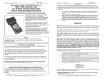
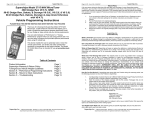
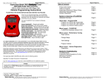
Page 1 of 20 0165B 3601 03/29/2007 Superchips Inc. Superchips FIREFLY Combination Power Module and Boost/EGT Gauge 2004.5-2007 Dodge RAM Cummins Vehicle Programming Instructions PLEASE READ THIS ENTIRE INSTRUCTION SHEET BEFORE YOU PROCEED Thank you for choosing Superchips new FIREFLY, which features “On-The-Fly” technology via a touch screen gauge and power module. The new FIREFLY includes the following features: Touch Face programming Change Power Levels ‘On-The-Fly’ & set alarm points Power Level display 4 Graduated steps: Stock, Power Levels 1, 2, & 3 Boost Pressure display 0 to 50 PSI Exhaust Gas Temperature display 400(F) to 1500(F) Boost Pressure alarm Programmable set point to display alarm warning Exhaust Gas Temperature alarm Programmable set point to display alarm warning Pointer Auto-Intensity Gauge pointer brightness adjusts based on the amount of light shining on the gauge face Backlight Auto-Intensity Gauge backlight brightness adjusts based on amount of light shining on the gauge face Peak EGT and Boost Pressure display Gauge displays peak values by displaying a dot of light at the highest value hit In-Line Power Module The Superchips Firefly gauge connects to and communicates with our all new In-Line Power Module. This unique combination allows the ability to display Exhaust Gas Temperatures and Turbo Boost Pressures, but also displays and switches power levels ‘On-The-Fly’. Power is increased over stock throughout the entire RPM range and is most noticeable in the midrange RPM’s. This greatly improves drivability and towing performance. Transmission downshifting is greatly reduced, especially while passing or towing. Your FIREFLY Combination Power Module and Boost/EGT Gauge is setup specifically for your 2004.5-2007 Dodge RAM Cummins. Page 2 of 20 0165B 3601 03/29/2007 Superchips Inc. Table of Contents Product Information Table of Contents Superchips Warranty & Return Policy Page 1 Page 2 Page 3 Overview of Firefly Parts Overview Pictures (1 of 2) Parts Overview Descriptions (1 of 2) Parts Overview Pictures (2 of 2) Parts Overview Descriptions (2 of 2) Tools Overview Pictures (1 of 1) – For Reference Tools Overview Descriptions (1 of 1) – For Reference Page 4 Page 5 Page 6 Page 7 Page 8 Page 9 Section A: Installation of Firefly – Part 1 Time Required & Level of Difficulty Sensor Connectors Power Module & Gauge Cables Power & Ground Connectors Routing & Connecting Gauge Cable Page 10 Page 10 Page 11 Page 12 Page 13 Section A: Installation of Firefly – Part 2 Time Required & Level of Difficulty EGT Probe: Exhaust Manifold Preparation EGT Probe in Exhaust Manifold Page 10 Page 14 Page 15 Section B: Operation of Firefly On-The-Fly Power Level Adjustment Description of Power Levels Setting EGT & Boost Level Alarms Setting up “Demo Mode” Page 16 Page 16 Page 17 Page 17 Section C: FAQ – Frequently Asked Questions Frequently Asked Questions (F.A.Q.) Return Form Page 18 Page 20 FIREFLY is designed for STOCK VEHICLES ONLY and was not designed or tested on modified vehicles. Note: Most of this kit can be installed with general automotive knowledge and minimal hand tools. For the EGT (Exhaust Gas Temperature) display to function properly the supplied EGT probe (also called thermocouple) must be mounted and connected. Drilling & tapping of a hole on the exhaust manifold is required to install the EGT probe. The Firefly unit will function as a single gauge displaying Turbo Boost and allow On-The-Fly Power Tuning if the EGT package is not installed. If, after reading the instructions, you do not feel confident or technically capable to use tools similar to those listed in figures 7, 8, and 9 in the following pages please seek a qualified diesel service shop for installation. Superchips Inc. 1790 East Airport Blvd., Sanford, FL. 32773 (407) 585-7000 http://www.Superchips.com Superchip & Superchips are registered trademarks of Superchips, Inc. Superchips Inc. 1790 East Airport Blvd., Sanford, FL. 32773 (407) 585-7000 http://www.Superchips.com Superchip & Superchips are registered trademarks of Superchips, Inc. Page 3 of 20 Superchips Inc. 0165B 3601 03/29/2007 Page 4 of 20 Refund Policy If for any reason during the first thirty (30) days after your purchase of a new Superchips product (“Product”), you may return it to the place you bought it for a full refund of the purchase price, credit or a replacement Product at the dealer’s discretion. This Guarantee does not apply to products purchased from auctions nor does it apply to Products purchased used. Follow these procedures to get your refund or replacement. 1. 2. 3. 4. If you are returning a MicroTuner or Flashpaq, use the MicroTuner or Flashpaq to return your vehicle to the stock settings for the vehicle. Instructions are included in the user manual. Put the Product back in its original packaging. Make a copy of your sales receipt. The sales receipt must be from the location where you purchased your Product and must include the name of the business, its address, and the part number or description of the applicable Superchips Product. Invoices, credit card statements, or sales receipts from an online payment service company will not be accepted. Return the Product in its original packaging with a copy of the sales receipt to the place of purchase. Superchips, Inc. Limited Warranty Superchips Inc. 0165B 3601 03/29/2007 Firefly Parts Overview Pictures (1 of 2) 1A 1B 1D What is Covered? This warranty covers any defects in materials or workmanship in any product sold by Superchips or its affiliates through its authorized dealers (“Product”). Warranty is valid only for new products purchased through Authorized Dealers; (Proof of purchase is required for all warranty claims). How Long Does the Coverage Last? This warranty lasts for one (1) year from the date of purchase. Coverage terminates if you sell or otherwise transfer ownership of the Product. 1C What will Superchips Do? Superchips will repair or replace the defective or malfunctioning Product or any defective or malfunctioning part thereof at no charge. This warranty covers parts and labor only. Superchips will reimburse you for all reasonable shipping charges within the first thirty (30) days of purchase. What Does This Warranty Not Cover? This warranty does not cover any problem that is caused by abuse, misuse, acts of God, or improper installation or repair by non-Superchips personnel. This warranty does not cover Products purchased used nor does it apply to Products purchased from auctions or entities that are not Superchips’ authorized dealers. This warranty does not cover damage to your vehicle. Use of the Product to change the performance characteristics of your vehicle could invalidate the warranty provided by the vehicle manufacturer. Consult your vehicle warranty before using the Product on your vehicle. SUPERCHIPS SHALL NOT BE LIABLE TO YOU FOR ANY CONSEQUENTIAL, SPECIAL, OR INCIDENTAL DAMAGES. SOME STATES DO NOT ALLOW THE EXCLUSION OR LIMITATION OF INCIDENTAL OR CONSEQUENTIAL DAMAGES, SO THE ABOVE LIMITATION OR EXCLUSION MAY NOT APPLY TO YOU. Figure 1. 2C 2A How Do You Get Service? If something goes wrong with your Product during the warranty period, use the following procedure to return the Product to Superchips. 1. 2. 3. 4. Call Superchips’ Customer Service at 1-888-227-2447 Monday through Friday from 8:00 am to 5:00 pm EST to request a Return Authorization (“RA”) number. Mark the outside of the shipping package with the RA number. Packages that are not marked with the RA number will be refused. Make a copy of your sales receipt. The sales receipt must be from the location where you purchased your Product and must include the name of the business where you purchased the Product and the address of such business. Invoices, credit card statements, or sales receipts from an online payment service company will not be accepted. Send the Product, postage paid, the copy of the sales receipt, a brief written description of the problem, and your contact information to: Superchips, Inc. 1790 East Airport Blvd Sanford, FL 32773 Attn: Warranty Claims 2D Figure 2. 2B 2E 3B 3A We will inspect the Product and either repair it or replace it with a new or rebuilt Product. We reserve the right to use refurbished parts when making repairs. Figure 3. Your Rights Under State Law: This warranty gives you specific legal rights, and you may also have other rights which vary from state to state. Superchips Inc. 1790 East Airport Blvd., Sanford, FL. 32773 (407) 585-7000 http://www.Superchips.com Superchip & Superchips are registered trademarks of Superchips, Inc. Superchips Inc. 3C 1790 East Airport Blvd., Sanford, FL. 32773 (407) 585-7000 http://www.Superchips.com Superchip & Superchips are registered trademarks of Superchips, Inc. Page 5 of 20 0165B 3601 03/29/2007 Superchips Inc. Firefly Parts Overview Descriptions (1 of 2) Page 6 of 20 0165B 3601 03/29/2007 Superchips Inc. Firefly Parts Overview Pictures (2 of 2) Figure 1. Gauge Cable Assembly Part Number: 9-0179 1A. 1B. 1C. 1D. Gauge Multiple Pin Connector male-end (black) Power Connector female-end (single red wire) Ground Connector round-end (singe black wire) Gauge Multiple Pin Connector male-end (green) Figure 2. Power Module & Sensor Cable Assembly Part Number: 9-0181 2A. 2B. 2C. 2D. 2E. MAP Sensor Connectors Fuel Pressure Sensor Connectors Gauge Multiple Pin Connector female-end (green) (Caution must be used when unlocking / opening this end) EGT Thermocouple color / length coded round-ends Power Module Wire Harness female-end (black) Figure 3. EGT (Exhaust Gas Temperature) Package Part Number: 9-0180 3A. EGT Thermocouple color / length coded round-ends, containing screws & safety-locking nuts 3B. Heat-Shrink tubing, 2 equal length pieces (Place over the EGT Thermocouple connectors before assembly) 3C. Thermocouple, Nut, Double-Threaded Male adapter/bung Superchips Inc. 1790 East Airport Blvd., Sanford, FL. 32773 (407) 585-7000 http://www.Superchips.com Superchip & Superchips are registered trademarks of Superchips, Inc. Superchips Inc. 1790 East Airport Blvd., Sanford, FL. 32773 (407) 585-7000 http://www.Superchips.com Superchip & Superchips are registered trademarks of Superchips, Inc. Page 7 of 20 0165B 3601 03/29/2007 Superchips Inc. Firefly Parts Overview Descriptions (2 of 2) Page 8 of 20 Superchips Inc. 0165B 3601 03/29/2007 Firefly Suggested Tools Overview Pictures (1 of 1) – (For Reference Only) Figure 4. Lazer Gauge Part Number: 9-0182 4A. Gauge Multiple Pin Connector female-end (black) Figure 5. Sensor & Power Module Part Number: 26-0001 Figure 7. 5A. Sensor & Power Module Wire Harness Receptacle Figure 6. Bladed Fuse Power Tap (gold) Part Number: PowerTap For installing onto an existing fuse to tap power, connects to part 1B. Figure 8. Figure 9. Firefly installation support pictures Engine Specifications Label Sensor Connections Figure 10 Superchips Inc. 1790 East Airport Blvd., Sanford, FL. 32773 (407) 585-7000 http://www.Superchips.com Superchip & Superchips are registered trademarks of Superchips, Inc. Superchips Inc. . 1790 East Airport Blvd., Sanford, FL. 32773 (407) 585-7000 http://www.Superchips.com Superchip & Superchips are registered trademarks of Superchips, Inc. Page 9 of 20 0165B 3601 03/29/2007 Superchips Inc. Firefly Tools Overview Descriptions (1 of 1) –(For Reference Only) Page 10 of 20 0165B 3601 03/29/2007 Section A – Installation of Firefly Superchips Inc. It is recommended that your motor be cool to work on to avoid the possibility of burns. Note: The Firefly unit will function as a single gauge displaying Turbo Boost and allow On-The-Fly Power Tuning if part 3, the EGT package is not installed. If, after reading the instructions, you do not feel confident or technically capable to use tools similar to those in figures 7, 8, and 9 please seek a qualified diesel service shop. Ensure your vehicle is turned off and the keys are removed from the ignition. Before beginning installation remove both battery cable grounds (negatives). Installation Time & Degree of Difficulty Figure 7. Small Diameter Telescopic Magnet Tool Part Number: N/A For removing any metal shavings created during the use of part 8. The Firefly is designed with speed of installation in mind. Most connectors are color coded for snap-together installation. This installation can be seen as two parts: Figure 8. High Strength Drill Bit: 21/64” (inch) Part Number: N/A For drilling the exhaust manifold to mount part 3C, Thermocouple. This provides the ability to monitor EGT – Exhaust Gas Temperatures. Part 1 – Installation of the Lazer Gauge & Power Module Level of Difficulty: Low Time Expected: 45 Minutes Tools Required: Minimal (see parts list) Part 2 – Installation of the EGT Probe Level of Difficulty: Moderate Time Expected: 45 Minutes Tools Required: Intermediate (see reference list) Figure 9. High Strength Hole Tap: NPT 1/8” (inch) 27 Pitch Part Number: N/A For threading the hole that was created in the manifold for part 3C. Firefly installation support picture descriptions Install part 2A, MAP Sensor Connectors 1. Figure 10. Drivers side engine reference: Engine Specifications Label for 2004.5 through 2007 will read: “Advertised HP @ 325HP” Sensor Connections shown for location 2. 3. Familiarize yourself with the lock release tab on the male-end connector on part 2A. (This will aid in disconnecting the factory connector from the MAP sensor on the motor.) Disconnect the factory installed MAP Sensor Connector. Install the male-end connector on part 2A into the MAP sensor on the motor. Install part 2B, Fuel Pressure Sensor Connectors 1. 2. 3. Familiarize yourself with the lock release tab on the male-end connector on part 2B. (This will aid in disconnecting the factory connector from the MAP sensor on the motor.) Disconnect the factory installed Fuel Pressure Sensor Connector. Install the male-end connector on part 2B into the MAP sensor on the motor, and the female end of 2B into the Engine Harness on the motor. Squeeze tab to disconnect Pressure Sensor Lift tab to disconnect Map Sensor Reference Picture for installation: Parts 2A & 2B Superchips Inc. 1790 East Airport Blvd., Sanford, FL. 32773 (407) 585-7000 http://www.Superchips.com Superchip & Superchips are registered trademarks of Superchips, Inc. Superchips Inc. 1790 East Airport Blvd., Sanford, FL. 32773 (407) 585-7000 http://www.Superchips.com Superchip & Superchips are registered trademarks of Superchips, Inc. Page 11 of 20 Superchips Inc. 0165B 3601 03/29/2007 Page 12 of 20 Section A – Installation of Firefly Superchips Inc. 0165B 3601 03/29/2007 Section A – Installation of Firefly Install part 2E, Sensor & Power Module Wire Harness plug into part 5A, Sensor & Power Module Receptacle Install parts 1B & 1C, the power and ground connectors 1. This is so the Firefly can reference sensor information during cranking and while running. 2. Locate a suitable place for mounting part 5, Sensor & Power Module (A typical location is on top of the Fuse & Relay Center Cover – as shown below) While carefully matching the keyed connectors of 2E and 5A insert and lock them. Note: The red power connector, 1B, must be powered while the engine is starting and running. It is usually easiest to locate a fuse that supplies power to a vehicle powertrain system, such as ECM (Engine Control Module), TCM (Transmission Control Module) or FICM (Fuel Injection Control Module). The ‘Control Modules’ are always supplied power while starting (cranking) as well as when the vehicle is running. Refer to the inside of the fuse cover for locations. 1. Notice the pair of black and red wires extending out of the connector, part 1D. At their end points you will recognize parts 1B & 1C, Power & Ground connectors. Inserting Keyed Connectors: Step 2 Blown up image: wiring to parts 1B & 1C Selecting a location for part 5: Step 1 2. Install part 1C, the ground connector as shown. Remove the existing bolt and add it on. (Locations vary, but look for the heavy black ground wires) Install part 1D, Gauge Multiple Pin Connector male-end (green) to part 2C, Gauge Multiple Pin Connector female-end (green) 1. While carefully matching the keyed connectors of 1D and 2C insert and lock them. (Note: Once assembled follow the warning on the green connectors to unlock – lift the tab.) Bladed Fuse Power Tap installed: Part 6 (Needs to be firmly seated) Ground connector installed: Part 1C 3. Install part 6, Bladed Fuse Power Tap, on a fuse that has power during starting as well as while running (see note above), then part 1B, Power Connector. Replace the cover. Bladed Fuse Power Tap Installed Power Connector, 1B, installed Notice the warning Label for disconnection: Parts 1D & 2C and the wiring: Parts 1B & 1C Superchips Inc. 1790 East Airport Blvd., Sanford, FL. 32773 (407) 585-7000 http://www.Superchips.com Superchip & Superchips are registered trademarks of Superchips, Inc. Example: 2004.5 uses fuse# 50, 2005 Vehicles use fuse# 49 & 2006-07 Vehicles use fuse# 28 Check your vehicle owner manual. Power connections may vary. Superchips Inc. 1790 East Airport Blvd., Sanford, FL. 32773 (407) 585-7000 http://www.Superchips.com Superchip & Superchips are registered trademarks of Superchips, Inc. Page 13 of 20 0165B 3601 03/29/2007 Superchips Inc. Page 14 of 20 Route Gauge Cable Connector, part number 1A, into the cabin 1. 2. Uncoil the Gauge Cable Assembly and locate part 1A, Gauge Multiple Pin Connector Locate the large grommets on the driver’s side firewall, behind the driver’s side battery Superchips Inc. 0165B 3601 03/29/2007 Section A – Installation of Firefly Section A – Installation of Firefly Installation of the part 3, EGT (Exhaust Gas Temperature) Probe Kit Note: The Firefly unit will function as a Boost Gauge and On-The-Fly Power Module if part 3, the EGT package is not installed. If, after reading the instructions, you do not feel confident or technically capable to use tools similar to those shown on page 8, in figures 7, 8, and 9 please seek a qualified diesel service shop. Reminder: Extreme care must be taken to prevent contamination of the turbocharger inlet with metal chips during the drilling and tapping operation. 1. 2. Review the sketch below so that you fully understand the installation process. Locate the engine’s exhaust manifold which is on the passenger side (see picture). Reference: Zoom-Out Reference: Zoom-In Manual transmission clutch slave cylinder grommet (left), wiring loom grommet (right) 3. It is recommended that part 1A be routed through one of these locations. (Manual transmission vehicles will have the left grommet populated with the clutch assy.) The left side grommet material is rigid, so drilling may be easier. The right side grommet material is flexible. Cutting the grommet and/or tape may be easier. (2007 vehicles may have a double walled grommet – this visible one and one inside the cab.) Next, attempt to route the 1A cable assembly through the same hole as the wiring loom. If it is too tight, a separate hole may be needed. Always take care and use caution when working near existing wiring to avoid damage. Route Gauge Cable Connector, part number 1A, inside the cabin up the left A pillar. In this example a 3 pod ‘pillar mount’ is shown. Due to vehicle mechanical differences, color variations, customer mounting preferences, etc a gauge mount is not supplied with this kit. Concept Sketch: Part 3C 3. Recommended Location in Top of Manifold Determine a location to drill the exhaust manifold, a vertical (top-down) example is shown. Drill the hole for the EGT probe, such as shown in part 8 - a 90 degree drill is recommended. For Your convenience Superchips stocks single pod A-pillar mounts from Propods. 1. Slowly drill the manifold with light, even pressure using a high-strength 21/64” (inch) bit. 2. As you create metal shavings stop drilling! Carefully blow or wipe them away. (This step is highly important to reduce the possibility shavings that fall inside the manifold.) Part Numbers For 2003-2007 Model Year Dodge Ram: 5900 for black and 5901 for light gray. 3. 4. Repeat step 5 several times rather than drill aggressively and create large debris. As you begin to break through continue to drill slowly and evenly. This will help create fine shavings, continue until the hole is complete. Utilize a Small Telescopic Pen Type Magnet, such as shown in part 7. 4. Connect part number 4 & 4A, Gauge and Connector to 1A, the Gauge Cable Assembly. Because this gauge uses the full arc (full circle) to display values, it should be set eye-level. In this example the gauge is set up for a tall driver, mounted in the top pod location. Please keep in mind that this a touch-face gauge; mounting this gauge where motion or vision may be restricted or hazardous is not recommended. 1. 2. 3. Thread the newly drilled hole with Tap NPT 1/8” (inch) 27 Pitch, such as shown in part 9. 1. 2. 3. 4. Superchips Inc. 1790 East Airport Blvd., Sanford, FL. 32773 (407) 585-7000 http://www.Superchips.com Superchip & Superchips are registered trademarks of Superchips, Inc. Vertically lower the magnet into the manifold through the recently drilled hole. Gently rotate the magnet around to pickup any metal shavings / debris. Slowly and carefully extract the magnet so as not to knock any shavings off, repeat. Center the tapered tap in the newly drilled hole. While maintaining a slow speed, but consistent pressure rotate the tap to thread the hole. It is normal for minor metal shavings to occur. As you are threading the hole, you are removing minor amounts of metal. Once fully threaded repeat usage of the magnet, as stated above. Superchips Inc. 1790 East Airport Blvd., Sanford, FL. 32773 (407) 585-7000 http://www.Superchips.com Superchip & Superchips are registered trademarks of Superchips, Inc. Page 15 of 20 Superchips Inc. 0165B 3601 03/29/2007 Page 16 of 20 Install the dual threaded ‘bung’ and EGT probe, part 3C. (The EGT Probe Assy, part 3C ships assembled, be aware of which end you use!) Completed Install If you have the EGT Probe and 2 sided threaded bung separated it is recommended to reconnect these two pieces to ensure you know which end to use in the manifold. (The coarse end of the bung fits the compression nut on the EGT Probe!) After ensuring you have the proper end of the threaded bung (the fine pitch threaded end), insert the bung by hand and begin tightening until too much resistance is felt. (This bung end is tapered and will only tighten so far by hand and by tool) 3. Using a 9/16” or 14mm wrench tighten the bung assembly further. Use caution to not over-tighten or strip the newly made hole. (This bung end is tapered and will only tighten so far by hand or by tool) 4. Once the bung is mounted in the manifold insert the remainder of EGT Probe assembly, part 3C, through it. 5. Begin tightening by hand until too much resistance is felt. 6. Place a 9/16” or 14mm wrench on the bung assembly then with the other wrench 9/16” or 14mm tighten the compression nut further. This is to keep a ‘counter-torque’ wrench applied so as not to loosen or damage the bung threads in the manifold. Route the EGT Thermocouple wiring to the Fuse & Relay Center but keep it away from any hot exhaust components such as the manifold or the turbo charger. Also avoid contact or close proximity to all high voltage plug wires. Install the colored coded EGT connectors, part 3A to their mated connectors of part 2D. (Do not use any other type of wire or extension cable on these fittings, special wiring is used) Prior shrinking Section B – Operation of Firefly On-The-Fly Power Level Adjustment – Gently tap and release the gauge face to change the power level. The gauge indicates which level (0-3) the Firefly is operating in. 1. 2. 7. Superchips Inc. 0165B 3601 03/29/2007 Section A – Installation of Firefly 1. Unscrew the existing lock nuts in both EGT connectors, part 3A. 2. Slide 1 piece of heat shrink tubing past each EGT connector. Power Level Level 0: Level 1: Level 2: Level 3: Horsepower Stock 25 45 65 Torque Stock 50 77 150 Towing Capabilities OEM Limit OEM Limit OEM Limit Towing NOT Recommended These power gains are representative of an actual test vehicle. Power gains may vary somewhat on different vehicles or in different geographic settings. The first thing you should notice, especially if this is your first time driving a diesel truck with a performance module, is more power evidenced by quicker launches, better passing and acceleration, and possibly better fuel economy. You should also notice your truck is more responsive. Please monitor your speeds with this new product. Be cautious and be aware that there may be an adjustment period to your newfound power. Towing The great thing about Firefly Module is that it was created with towing in mind. The Firefly provides additional horsepower and torque to the wheels throughout the RPM range. You should now be able to pull your load with less effort, accelerate to cruise speeds quicker and may notice you use less throttle under the same driving conditions compared to stock. Power level 3 is designed to maximum performance and should never be used while towing. When driven responsibly, and EGT’s are monitored, level 3 will not stress the stock engine or transmission as long as you are not towing. Exhaust Gas Temperature The EGT tells you how hot the exhaust gases are in the exhaust manifold coming from the engine. This is important because you shouldn’t let them run for long periods above 1350 F. The higher the power level selected, the more fuel is fed to the engine and the higher the amount of power that is sent to the transmission, remember to monitor your EGT’s while towing. This will protect you from putting too much stress on the engine and transmission. Level 2 is a good all-around mode, allowing for better economy and better performance, while not stressing the engine and transmission. We recommend that you run your truck in level 1 or 2 for your normal daily activities. 3. With the heat shrink tubing over the wire now tighten both EGT connectors. (The wires are color and length coded and tighten via lock nuts.) 4. Center the heat shrink tubing over the lock nuts, then heat it to shrink it into place. (A blow dryer is preferred, but a lighter may be used with caution, avoid melting.) Completed Install Superchips Inc. 1790 East Airport Blvd., Sanford, FL. 32773 (407) 585-7000 http://www.Superchips.com Superchip & Superchips are registered trademarks of Superchips, Inc. Superchips Inc. 1790 East Airport Blvd., Sanford, FL. 32773 (407) 585-7000 http://www.Superchips.com Superchip & Superchips are registered trademarks of Superchips, Inc. Page 17 of 20 0165B 3601 03/29/2007 Superchips Inc. Section B – Operation of Firefly The Firefly supports dual alarms: EGT (Exhuast Gas Temperature) in degrees F (Farenheit) Boost (Turbo Boost Pressure) in PSI (Pounds per Square Inch) Note: Gauges are tested with various preset alarm levels. Your gauge may exhibit the following and is not malfunctioning or defective. Once the alarm level is met for either EGT or Boost the gauge face aluminates red and the arc will flash rapidly alerting you that your pre-set limit has been exceeded. Setting the EGT Alarm – The Lazer Gauge alarm functions can be programmed by touching the gauge face. To program the EGT level alarm, touch and hold the gauge face until the EGT alarm is displayed. This can be recognized by the presence of the blue arc on the EGT display. Next, momentarily release then touch and hold it until the arc reaches the intended set point. If the arc direction needs to be reversed momentarily release then touch and hold the lens, again. This process can be repeated to reverse direction several times to fine tune your set points. When you release your finger from the gauge face the alarm point is set and the gauge will return to normal operation in about 2 seconds - it will switch from red backlight to normal, white back light. Setting the Boost Alarm – The Lazer Gauge alarm functions can be programmed by touching the gauge face. To program the Boost level alarm, touch and hold the gauge face until the Boost alarm is displayed. This can be recognized by the presence of the blue arc on the Boost display. Next, momentarily release then touch and hold it until the arc reaches the intended set point. If the arc direction needs to be reversed momentarily release then touch and hold the lens, again. This process can be repeated to reverse direction several times to fine tune your set points. When you release your finger from the gauge face the alarm point is set and the gauge will return to normal operation in about 2 seconds - it will switch from the red backlight to the white backlight. Demo Mode – The Lazer Gauge has a demonstration mode that will illustrate the gauge arc moving back and fourth from minimum to maximum. To select the demo mode touch and hold the gauge face for 10 seconds or until the both arcs begin moving. One of three speeds can be selected for the arc by touching the face. As you tap and release, the speed will begin at the slowest rate, followed by the intermediate, and finally the fastest. You can tap the face to repeatedly view these speeds. The demo mode will repeat until power is turned off. Demo mode can also be used when the vehicle is not running as long as the ignition switch is in run (on) position. Page 18 of 20 0165B 3601 03/29/2007 Superchips Inc. Section C – FAQ – Frequently Asked Questions A. What is EGT and what does it mean? EGT is a terminology primarily used with diesel vehicles it stands for Exhaust Gas Temperature. EGT’s are measured in degrees (Farenheit – in our product) and show how hot your engine exhaust is running. EGT’s typically rise dramatically when towing heavy loads or when hard acceleration is requested and turbo boost increases. Typically a stock vehicle is well equipped to handle various EGT levels as long as OEM towing / hauling limits are observed. B. How does the gauge display the EGT info? EGT or Exhaust Gas Temperature is displayed from 400(F) to 1500 (F). Approximately 1/3 of the gauge is utilized for displaying EGT data. The gauge supplies readings only when the EGT Probe (supplied) is properly mounted and wired to the power module. C. Does the EGT Probe have to be installed for the Firefly to work? No, the EGT Probe is not required for the Firefly to operate. However, if you do not install the EGT probe it is recommended you seek the support of a qualified diesel service shop. You can enjoy changing Power Levels “On-The-Fly” and monitor Turbo Boost Pressure, but a reading will not be shown on the EGT monitor. Monitoring EGT’s is highly encouraged when towing or hauling heavy loads and when power adder devices are installed. This real time data allows you to monitor EGT levels, especially if you have vehicle modifications, heavy towing or hauling conditions, or are running power adder devices. D. I just installed the Firefly and started my truck but my EGT and Boost gauges are not reading any values, is it working correctly? Typically, turbo diesel vehicles do not produce Turbo Boost or noticeable EGT’s at idle. Your vehicle probably idles around 350-400 degrees F; therefore, this is below the Firefly’s 500F minimum display and will not be shown. The Turbo Boost is at 0 PSI at start-up and idle, so here too, the Turbo Boost gauge will not display any data. However, you can check communications with the Lazer Gauge and power module (FAQ - E). E. How can I tell if my Lazer Gauge is working with my under-hood power module? The Lazer Gauge communicates with the under-hood power module to set the Power Level as well as to display Turbo Boost Pressure and EGT data. Tap (touch and release) the lower, center portion of the gauge face to switch power levels: • Immediately upon touch the gauge backlight should illuminate red st • The Power Level always changes on 1 touch. • Confirm the Power Level changes, you can tap twice if needed. • After release in approximately 2 seconds the red backlight will return to normal (white) • The Power Level should remain where it was set. o Communications are OK if: The Power Level remains, as changed o Communications have failed if: The Power Level returns to what is before the change If the Power Level indicator returns to ZERO (0) then the Lazer Gauge is not communicating to the Power Module, check cabling and retry. F. Where does the Firefly get the Turbo Boost Pressure from? For EGT’s to be displayed your stock vehicle required installation of an EGT Probe (sensor) due to the fact that it was not equipped with one. Unlike the EGT Probe, your vehicle does have a MAP (Manifold Absolute Pressure) sensor, Firefly installation requires connection to this sensor and takes its reading from the factory installed part. Superchips Inc. 1790 East Airport Blvd., Sanford, FL. 32773 (407) 585-7000 http://www.Superchips.com Superchip & Superchips are registered trademarks of Superchips, Inc. Superchips Inc. 1790 East Airport Blvd., Sanford, FL. 32773 (407) 585-7000 http://www.Superchips.com Superchip & Superchips are registered trademarks of Superchips, Inc. Page 19 of 20 0165B 3601 03/29/2007 Superchips Inc. Section C – FAQ – Frequently Asked Questions G. Will my vibrant Lazer Gauge be too bright for night-time driving? No, the Lazer Gauge has Pointer and Backlight Auto-Intensity functions that react based on the amount of light shining on the gauge face. If you look closely you will see the sensor behind the number ‘30’ in the boost display – you may need to tilt the gauge into light to see it. H. Sometimes when I tap the Lazer Gauge it does not respond to my touch. The response should be instant! The Lazer Gauge is designed to sense touch only on the lower, center portion of the gauge face. If you are tapping the gauge higher than this or too quickly, it may not register. Try tapping the gauge face near the number ‘1000’ on the EGT display. If your fingers or the gauge face become dirty, please wipe off and try again. Page 20 of 20 Superchips Inc. 0165B 3601 03/29/2007 If it is necessary to return your Firefly to Superchips, please take a moment to copy and fill out this form. The following information will be necessary to process your request. Check list: Complete this form and have it available when you contact Superchips. Contact Superchips Customer Service @ 407.585.7000 to obtain an RA number. If an RA number has been issued, enter the RA number on the bottom of this form. Attach a photocopy of your purchase receipt to this form. Attach this form to the product being returned to Superchips. I. Where does the Lazer Gauge get its power from? The gauge requires 12V DC power (vehicle battery power) and sources this from under hood connections 1B & 1C which are installed at the fuse / relay center and vehicle ground at the inner fender. If the Lazer Gauge fails to power up check all connections and confirm the fuse location you have chosen supplies power during cranking (starting) as well as when running. Name:______________________________________________ J. Where does the power module get its power from? The power module requires 5V DC power and sources this from connection 2A which is installed at the vehicle MAP sensor location under the hood. Home Phone:__________________ Other phone: _______________ Street Address: _______________________________________ City: _______________________ State: _______ Zip: _________ Place of purchase: _____________________________________ Date of Purchase: _______________________ Vehicle Year: _____ Vehicle Make: ___________ Vehicle Model: ______________________ VIN Number: ______________________________________ Transmission: Automatic Manual Part Number: _____________________ Serial number on back of Power Module: ______________________ E-mail address: _____________________________________________________ RA Number:_________________ Prior to returning any product to Superchips, you must obtain an RA number; please contact Superchips customer service at 407.585.7000. Please attach a photocopy of sales receipt here. Superchips Inc. 1790 East Airport Blvd., Sanford, FL. 32773 (407) 585-7000 http://www.Superchips.com Superchip & Superchips are registered trademarks of Superchips, Inc. Superchips Inc. 1790 East Airport Blvd., Sanford, FL. 32773 (407) 585-7000 http://www.Superchips.com Superchip & Superchips are registered trademarks of Superchips, Inc.