1
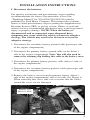
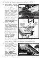
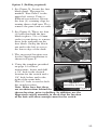
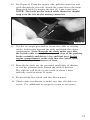
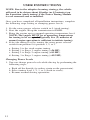
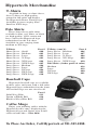
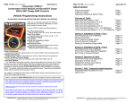
IN-LINE POWER TUNING MODULE
2003-2004 Ford 6.0L Power Stroke®
Super Duty F250/F350 & Excursion
Part #41042
STEP-BY-STEP INSTALLATION
INSTRUCTIONS
Part #593
© 2004-2005 Hypertech, Inc.
Revised 8.2.05
® Power Stroke is a registered
trademark of the Ford Motor Company
Kit Contains:
Hypertech Power Tuning Module
Wiring harness (connectors are marked for easy installation)
Hypertech rotary switch assembly
Hypertech mounting bracket (with module attached)
Hypertech switch plate (cable, switch with knob, connector/wire)
Small standard screwdriver
Installation and operation manual (instructions)
#10 Phillips-head screws (2 each)
Retaining plugs (2 each)
Tie-wraps (3 each)
One tube of Boss RTV sealer (0.5 oz.)
You will need the following:
Insulated adjustable wrench
(to tighten battery terminals and switch mounting nut)
Phillips-head screwdriver (for mounting bracket/module)
Standard (flat) screwdriver (for removing fuse panel)
10mm socket or nut-driver (for removing fuse block)
Drill and 1/8”, 3/8” and 1/2” drill bits
(for rotary switch installation)
Diagonal cutters (for removing tie-wrap excess)
2
PLEASE READ BEFORE INSTALLING THE
HYPERTECH IN-LINE POWER TUNING
MODULE FOR THE 6.0L POWER STROKE
Special instructions for the 6.0L Power Stroke
2003-2004 Ford Super Duty F250/F350 & Excursion
SPECIAL NOTE: Power Stroke engines built before 9/29/03
must be updated to the newest calibration level (B27.9 or
later) by an authorized Ford, Lincoln, or Mercury dealer.
Ford Motor Company’s Technical Service Bulletin No. 03-20-12
states the following…
“Some vehicles may exhibit various driveability conditions
listed below:
•
•
•
•
•
•
•
Rough/rolling idle when the engine is warm.
Rough/rolling idle and white smoke after hot restart.
Lacks power after initial start-up.
Cold idle kicker performance at warm ambient temps.
U0306 codes after reprogramming.
P2263 code set during extended idle.
False P0196 codes.”
According to this Technical Service Bulletin (Article No. 03-20-12),
a PTM/TCM/FICM module calibration level update is available
for vehicles equipped with the 6.0L Power Stroke engine built
before 9/29/03 that exhibit one (1) of the above conditions.
Since this problem can occur on completely stock engines,
modifying these particular vehicles to make even more power
could worsen the problem. For this reason, Hypertech WILL
NOT WARRANTY any damage claims to the vehicle or
product if their in-line Power Tuning Module is installed on
any vehicle equipped with the 6.0L Power Stroke engine that
has not been updated to the newest calibration level (B27.9 or
later) by an authorized Ford, Lincoln, or Mercury dealership.
In addition, Ford Motor Company’s Technical Service Bulletin
No. 04-09-03 states the following:
“ Some vehicles equipped with the 6.0L diesel engine may exhibit
engine oil diluted with fuel (OIL LEVEL MAY APPEAR OVER
FULL), runs rough, and/or a lower power condition.”
For this reason, Hypertech WILL NOT WARRANTY any
damage claims to the vehicle or product if their in-line Power
Tuning Module is installed on any vehicle equipped with the
6.0L Power Stroke engine that exhibits any of these conditions.
3
INSTALLATION INSTRUCTIONS
I. Disconnect the batteries
For specific instructions and precautionary steps regarding
recommendations for battery disconnection, refer to the
“Workshop Manual” for 2004 F250/350/450/550 vehicles,
published by Ford Motor Company. This manual also contains
battery-related precautionary steps regarding the Supplementary
Restraint System (SRS) or air bag system. Failure to read and
observe factory-recommended instructions may result in personal
injury or property damage. NOTE: When the battery is
disconnected and re-connected, some abnormal drive
symptoms may occur while the vehicle relearns its adaptive
strategy. The vehicle may need to be driven to re-learn its
adaptive strategy.
1. Disconnect the secondary battery ground cable (passenger side
of the engine compartment).
2. Disconnect the primary battery ground cable on the driver’s
side of the engine compartment. Note: You will also need to
remove the retaining clip holding this cable to the battery cover.
3. Disconnect the primary battery positive cable (driver’s side of
the engine compartment).
4. Disconnect the secondary battery positive cable (passenger side
of the engine compartment).
5. Remove the battery cover from the primary battery (driver’s
side of the engine compartment) and set it aside. See Figure A.
When removing this cover, take care to ensure that the cables
around the cover are not damaged.
Battery On
Driver’s Side
Figure A
4
II. Locate the Powertrain Control Module (PCM)
6. See Figure B. Locate the powertrain control module (PCM).
It is located on the right side of the engine compartment beside
the primary battery. The PCM has three (3) connectors visible
at the front, facing the battery.
PCM with three (3)
connectors
Battery On
Driver’s Side
Figure B
7. See Figure C. Remove the center connector by pinching
the lever lock (small tab or tongue in the middle of the
connector, as shown) and pushing the lever away from the
PCM. The connector will slide out as you push the lever.
Lever lock
Figure C
5
8.See Figure D. The cable for the center connector lies in the
space between the battery and the power steering fluid
reservoir. Pull the connector and cable out from this space and
re-route it so that the connector is between the power steering
reservoir and the brake fluid reservoir.
Power steering
reservoir
Center connector
from PCM
Brake fluid
reservoir
Figure D
III. Inspecting the Hypertech cable
9.The Hypertech
mounting bracket is
provided with the
in-line Power Tuning
Module and two (2)
mounting clips already
installed. NOTE:
If these cables are
NOT already
connected as shown in
Figure E, identify
them and connect
them now.
10. Manual Transmission
applications ONLY.
See Figure F.
Remove the retaining
plugs holding the clutch
fluid reservoir to the
bracket on the power
steering fluid reservoir
and lay the reservoir
out of the way, prior
to beginning this step.
C3 connector
C2 connector
Figure E
Retaining plugs
Power steering
reservoir
Clutch fluid
reservoir
Figure F
6
IV. Position the Hypertech mounting bracket & PTM
11. See Figure G. Keeping
the Hypertech cable out
of the way, position the
mounting bracket on the
rear side of the power
steering fluid reservoir.
There is a bracket with
two (2) holes on this
side of the power
steering fluid reservoir.
Align the mounting
clips with these holes
and secure the
Hypertech bracket
using the phillips-head
screws provided.
Mounting
bracket
Figure G
Retaining
plugs
Clutch
12. See Figure H. If you
fluid
PTM and
previously removed the
reservoir
mounting
clutch fluid reservoir
bracket
(Manual transmission
applications), re-mount
the reservoir to the
holes located above
the Hypertech in-line
Power Tuning Module
on the Hypertech
mounting bracket.
Two (2) retaining
plugs have been
Figure H
provided, in case
the originals were damaged when you removed them.
Push the retaining plugs in all the way to secure the
clutch fluid reservoir to the Hypertech mounting bracket.
13. See Figure I. The
Vehicle
large connector on the
PCM
Hypertech cable,
marked C5, will plug
into the PCM where
the factory cable was
removed in Step 7 on
page 5 (Figure C).
There must be
C5 connector
enough room beside
the cable to re-install
the primary battery cover.
7
Figure I
14. See Figure J. Route the remaining large connector (marked C4)
on the Hypertech cable between the power steering fluid
reservoir and the brake fluid reservoir. Position the two (2)
large connectors (one is the connector removed from the
middle of the PCM) to mate to each other. Mate the connectors
and lock the lever.
Figure J
V. Reconnect the batteries
NOTE: When the battery is disconnected and re-connected,
some abnormal conditions may occur while the vehicle
re-learns it adaptive strategy. This typically requires the
vehicle be driven about 10 miles (or fifteen minutes) in
the “stock tuning” (setting) mode of operation. This should
be done after installation is complete.
15. See Figure K. There is one (1) section of the Hypertech cable
remaining. It has a small, 4-pin connector (C6). Set this out of
the way of the primary battery and proceed with re-attaching
the battery cover and cables.
C6 connector
Figure K
8
16. Re-install the battery cover onto the primary battery (driver’s
side of the engine compartment). Make sure the cables
around the cover are positioned such that the cover can
be properly seated when installed. Connect the secondary
battery positive cable (passenger side of the engine
compartment). Connect the primary battery positive cable
(driver’s side of the engine compartment). Connect the
primary battery ground cable (driver’s side of the engine
compartment). Connect the secondary battery ground cable
(passenger side of the engine compartment).
INSTALLING ROTARY POWER SELECTOR
Below are two (2) possible ways to install the Hypertech Rotary
Power Selector for the Power Tuning Module. The first method
requires no drilling. The second requires some drilling and mounts
the Rotary Power Selector in the dash below the headlight controls.
The Rotary Power Selector can be mounted in any location in
the vehicle, as these are only suggestions of possible mounting
locations.
Option 1 (No drilling required)
1. See Figures L & M. Route the Rotary Power Selector switch
cable from the Hypertech Power Tuning Module along the
driver’s side inner fender
panel, past the hood hinge, and
toward the windshield molding
(as shown in Figure L). Then
route the cable beneath the
driver’s side door molding and
into the cab at the left edge of
the dashboard (as shown in
Figure M). Once this cable
routing is completed, attach
Figure L
the Rotary Power Selector
switch to the cable. The switch
can now be mounted in a
convenient location or the
cable and switch coiled for
storage behind the driver’s
side dashboard for easy access
when a tuning level change is
desired. (NOTE: This method
is provided for installations
where it is undesirable to
Figure M
drill a mounting hole in the
dashboard. For a more permanent installation of the
Rotary Power Selector switch, option 2 is provided.)
9
Option 2 (Drilling required)
1. See Figure N. Locate the fuse
block panel. The panel is
marked “Fuse Panel” in the
upper left corner. Using a
flathead screwdriver, loosen
the four (4) retaining clips by
turning them a half turn. Then
remove the panel and set aside.
2. See Figure O. There are four
(4) bolts that hold the fuse
block in place. Use a 10mm
socket or nut-driver to remove
these bolts and pull out the
fuse block. Swing the block
out and to the left to access
the lower edge of the dash.
3. The suggested location area
for the switch installation is
shown in Figure P.
Fuse block
Fuse block
panel
Figure N
Fuse block
Figure O
4. Using the template provided
on page 14 of these
instructions, locate and drill
a 3/8” hole in the desired
location for the switch and a
1/8” hole below and to the
right of the main hole.
This 1/8” hole is used to lock
Option 2
the switch in place.
mounting location
Note: Make sure that there
Figure P
are no obstructions behind the
chosen location, prior to drilling. In addition, use the
Hypertech switch assembly to check that the location
of the hole will allow enough room for the switch.
10
5. See Figure Q. On the Hypertech Rotary Power Selector switch,
remove the mounting nut and washer from the switch shaft.
There is one (1) additional ring on the switch shaft. The tab on
this ring needs to remain in position number 4 when the switch
is installed. From behind the panel, insert the switch into the
panel hole. Line up the positioning tab into the small drilled
hole. On the outside of the dash, place the provided Hypertech
switch plate over the shaft. Make sure that the plate is lined up
so that the numbers 1 and 2 are spaced equally on either side
of the 12 o’clock position. Secure the switch in place with the
washer and mounting nut. Using the small screwdriver
provided, install the knob onto the switch shaft. The screw
should set against the flat portion of the knob shaft. Rotate the
knob left (counter-clockwise) until you reach the stop. The
white indicator on the knob should now point to the number 0
on the switch plate.
6. Temporarily re-install the fuse block (Step 2) so that it is out of
the way during the next step.
Headlight
controls
Hypertech
rotary switch
Figure Q
Rectangular
grommet
Figure R
7. See Figure R. From inside the vehicle, look below the dash at
the firewall, behind the parking brake, and locate the large
rectangular grommet. Using a 1/2” drill bit, carefully drill
a hole through the grommet into the engine compartment.
(Note: Prior to drilling, make sure that no obstructions
exist on the engine side of the grommet.)
8. Remove the fuse block and pull to the side, as performed in
Step 2 of the power selector installation.
9. Beneath the dash, route the switch cable along existing cable
paths toward the 1/2” hole. Feed the connector through the
1/2” hole.
11
10. See Figure S. From the engine side, pull the connector and
cable through the firewall. Attach the connector to the main
Hypertech cable by mating the two (2) 4-pin connectors.
NOTE: The latch on the switch cable connector should
snap over the tab on the mating connector.
Figure S
11. Use the tie-wraps provided to secure the cable to existing
cables, both inside beneath the dash and inside the engine
compartment. Note: Beneath the dash, make sure that
the switch cable is out of the way and clear of the parking
brake assembly and driver’s leg and foot area. In the
engine compartment, make sure that the switch cable
is routed away from sources of heat.
12. Beneath the dash, use the provided small tube of silicone
to seal the grommet hole around the cable if desired.
The silicone will be dry to the touch in about 1 hour,
and fully cured in about 24 hours.
13. Re-install the fuse block and fuse block panel.
14. Check entire installation to make sure that all cables are
secure. Use additional tie-wraps to secure as necessary.
12
USER INSTRUCTIONS
NOTE: Due to the adaptive learning strategy, the vehicle
will need to be driven about 10 miles (or 15 minutes) on
the 0 position (stock tuning) if the Power Tuning Module
is ever removed and re-installed.
Once you have completed all installation instructions, complete
the following steps setting or changing power levels.
1. Set the rotary power selector switch to 0 (stock tuning).
2. Start the engine. Keep the transmission in PARK.
3. Bring the engine up to a normal operating temperature level.
NOTE: The engine MUST be at operating temperature
for tuning to be accepted (Typically five (5) minutes of
normal engine operation is sufficient to initiate tuning).
4. Select the tuning level by turning the rotary power selector
switch from position 0 to position 1, 2, or 3.
a. Setting 0 is the stock engine tuning.
b. Setting 1 is Stage 1 engine tuning (+56 HP).
c. Setting 2 is Stage 2 engine tuning (+82 HP).
d. Setting 3 is Stage 3 engine tuning (+125 HP).
Changing Power Levels
1. You can change power levels while driving by performing the
following steps:
a. Back off the throttle (to reduce strain on the powertrain).
b. Select tuning level 1, 2, 3, or 0 (back-to-stock).
c. Resume normal driving operations.
13
What To Do Before Taking Your Vehicle In For Service
If you take your vehicle to a dealer or mechanic for service,
you must first restore the vehicle’s stock tuning. Hypertech
recommends you temporarily remove the Power Tuning Module,
even if the vehicle is restored to stock tuning. This assures the
Hypertech Power Tuning Module will not interfere with any
diagnostic procedures that may be performed during vehicle
servicing. The Hypertech Power Tuning Module for the 20032004 6.0L Ford Power Stroke can be restored to stock tuning by
either of two methods: (1) placing the Tuning Level Selector
switch in the “0” position or (2) removing the Power Tuning
Module. Once this service has been completed, you may reinstall the system by repeating the initial installation steps. If
you have any questions related to service issues, please call
Hypertech technical services at 901-385-1888.
PRODUCT WARRANTY
Warranty only applies to the original purchaser of a Hypertech
product. (Note: Warranty for the Hypertech Power Tuning
Module for 6.0L Ford Power Stroke will not apply, if used on
engines built prior to 9/29/03 and not updated to the B27.9
calibration.)
Template for switch installation
as described on Page 14
3/8” hole (main)
1/8” hole
14
SPECIALTY AUTO PARTS
CONSUMER’S BILL OF RIGHTS
Your Rights To Personalize Your Vehicle
Article 1: You have the Right to buy high-quality, reliable aftermarket
performance and specialty parts, accessories, and styling options.
Article 2: You have the Right to use high-quality aftermarket parts
and know that your new vehicle warranty claims will be
honored. In fact, your vehicle dealer may not reject a
warranty claim simply because an aftermarket product is
present. A warranty denial under such circumstances may be
proper only if an aftermarket part caused the failure being claimed.
Article 3: You have the Right to install and use emissions-legal
aftermarket performance parts without incurring hassles
and onerous procedures during state vehicle emissions inspections.
Article 4: You have the Right to actively oppose any proposed
(or existing) laws or regulations that will reduce your
freedom to use aftermarket automotive parts and service
or will curtail your ability to take part in the automotive
hobbies of your choice.
Article 5: You have the Right to patronize independent retail
stores and shops for vehicle parts and service. The U.S.
aftermarket offers the world’s finest selection of
performance and specialty parts, accessories, and styling
options. These aftermarket products satisfy the most
discriminating customers seeking personalized vehicles
for today’s lifestyle.
The Consumer’s Bill Of Rights courtesy of
Specialty Equipment Market Association (SEMA)
15
Typical Performance Gains
NOTE: All dynamometer tests are performed under controlled
conditions. Results may vary, depending on the specific vehicle,
altitude, temperature, fuel used, and various other conditions that
affect vehicle performance. Power gains shown are specific to the
vehicle tested and representative of the average gains verified.
For a color, printable power graph of your particular
application, check out our website at www.hypertech.com.
16
Hypertech Merchandise
T- Shirts
Available in long- or short-sleeve,
these T-shirts are high-quality,
printed in full-color and display
the Hypertech Power Tuning logo.
Available in sizes ranging from
Small to XXX-large.
Polo Shirts
These short-sleeve polo shirts
available in blue, red, white, or black
are high-quality 100% cotton and
have a full-color Hypertech logo
embroidered on the left chest.
Available in sizes ranging from
medium to XX-large.
T-Shirts
Short Sleeve - Small
Short Sleeve - Medium
Short Sleeve - Large
Short Sleeve - X-Large
Short Sleeve - XX-Large
Short Sleeve - XXX-Large
Long Sleeve - Medium
Long Sleeve - Large
Long Sleeve - X-Large
Long Sleeve - XX-Large
Long Sleeve - XXX-Large
Part #
600
601
602
603
604
605
606
607
608
609
610
T-Shirts (cont’d)
Long Sleeve - Medium
Long Sleeve - Large
Long Sleeve - X-Large
Long Sleeve - XX-Large
Long Sleeve - XXX-Large
Part #
606
607
608
609
610
Polo Shirts (Order part# & color)
Medium
638
Large
639
X-Large
640
XX-Large
641
Baseball Caps
Hypertech baseball caps are available
in three styles and come with a full-color
Hypertech logo embroidered on the front.
All baseball caps are one-size-fits-all.
Solid Navy Blue
Denim w/Khaki Bill
Khaki w/Navy Blue Bill
Part #
633
634
635
Coffee Mugs
Enjoy your morning coffee with the
Hypertech coffee mug, displaying the
Hypertech logo and engine icon in full
color on both sides - Part #626.
To Place An Order, Call Hypertech at 901-385-1888.
Notes