1
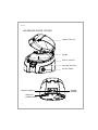
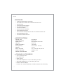
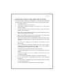
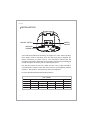
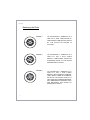
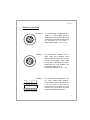
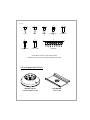
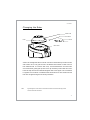
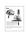
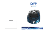
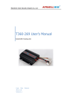
M08 User Guide Contents Standard Parts Listing 2 Introduction 3 Intended Use 3 Features 4 Specifications 4 Standard Accessories 4 Operating Conditions and Precautions 5 Installation 6 Operation 7-12 Care & Maintenance 13 Service and Repair Information 13 Warranty Statement Product Disposal 14-15 16 1 User Guide STANDARD PARTS LISTING PROTECTIVE LID ROTOR SAFETY SWITCH RELEASE BUTTON ON OFF KNOB ON/OFF SWITCH NON SLIP RUBBER BASE 2 POWER SOCKET User Guide INTRODUCTION Congratulations you are using the fixed speed personal Micro Centrifuge that offers simplicity, safety and ease of usage in a single package. This product has been designed after studying centrifuges and its usage in innumerable scenarios of the lab environment. The Micro centrifuge is supplied with 2 rotors - round rotor and strip rotor. The 8 x 2/1.5ml rotor can centrifuge up to 8 individual 2/1.5ml plastic micro tubes. The strip tube rotor is designed to centrifuge two strips of 8 x 0.2 ml strip tubes. This Micro Centrifuge can accept many different kinds of micro tubes including 0.2ml, 0.4ml and 0.5ml tubes when used with the reduction adapters supplied along with the unit. This Micro centrifuge is specially suitable for Microfiltration, cell separations, centrifugal tube sedimentation and spin down applications. Please read this manual thoroughly before operating the centrifuge. INTENDED USE Centrifuge is used in various laboratories to separate particles from suspension or even macromolecules from solutions according to their density. The different biological substances that are usually separated by centrifugation are microbial cells, mammalian cells, organelles, proteins, DNA and RNA. It is majorly used in research laboratories. Note : This user guide is intended to assist with the operation and care of the unit only and not for its repair. The customer should not attempt to service or repair the unit. If repairs are required, please contact the supplier. For your reference, make a note of the serial number, date of purchase and supplier here. Serial No. Purchase Date Supplier 3 User Guide FEATURES POSITION CLOSED MICRO TUBE ROTOR ELECTRONIC SAFETY BRAKE ON LID OPENING FOR USER SAFETY DIGITAL DISPLAY STARTS AND STOPS IN SECONDS EASY ACCESSON/OFF SWITCH LID SAFETY INTERLOCK SMOOTH AND QUIET RUNNING USER CALIBRATION FEATURE TINY FOOTPRINT CAN SQUEEZE EASILY ON TO A CROWDED COUNTER TOP INTERCHANGEABLE ROTORS LOW VOLTAGE POWER ADAPTOR SPECIFICATIONS MOTOR TYPE MAXIMUM SPEED SPEED TYPE MAX RCF SPEED ACCURACY SIZE (LxWxH) WEIGHT INPUT VOLTAGE OUTPUT VOLTAGE POWER CONSUMPTION DC MOTOR 6000 rpm Fixed speed 6000 RPM 2000 x g ±100 RPM 162 x 154 x 116 mm 1.1 Kg 100 - 240 VAC, 50/ 60 Hz 24VDC, 1.5A 15 W STANDARD ACCESSORIES 2/1.5 ml closed rotor PCR Strip rotor Allen wrench Individual adapters for 0.4/0.5 ml tubes, pack of 8 Individual adapters for 0.2 ml tubes, pack of 8 External Power Adaptor Product user manual, Warranty card & Declaration of Conformity 4 User Guide OPERATING CONDITIONS AND PRECAUTIONS The personal Micro centrifuge is designed to be safe under the following conditions when operated with necessary precautions mentioned hereunder: For indoor use only. Ambient temperature of 4°C to 65°C. Main supply voltage fluctuations not to exceed +/- 10% of the nominal voltage. Position at least 20 cm from walls, 20 cm from ceiling and 20 cm between other products. Make sure to always install the centrifuge on stable flat surfaces only & place it near the electrical outlet. Make sure to always load the rotor symmetrically every time. Each tube should be counterbalanced by another tube. Make sure to always use only specified Micro Centrifuge tubes made from plastic and designed to withstand centrifugal forces of at least 2000 g. Do not use the centrifuge in any manner not specified in these instructions. Do not operate the centrifuge without the rotor being properly attached to the shaft. Re-check by trying to pull it up manually, especially after rotor change or re-assembly. Do not move the centrifuge while the rotor is spinning. Do not fill tubes while they are in the rotor, liquid spillage may harm the unit. Do not put hands in the rotor chamber unless the rotor has completely stopped. Do not centrifuge flammable, explosive or corrosive materials. Do not use solvents or flammables near this or other electrical equipment. In case of the unit dropping from the table please check the casing for any cracks/damage. The centrifuge and its components are non autoclavable. 5 User Guide INSTALLATION ON/OFF SWITCH POWER SOCKET NON SLIP RUBBER BASE The fixed speed Personal Centrifuge is supplied in a Box. Open the Box, then gently remove centrifuge from the Box and plug-in adaptor pin before connecting to power source. The instruction manual and the accessories should be kept with the centrifuge. Please keep all packaging in safe storage for at least 2 year for warranty purposes. Put ‘On’ the switch at rear side, make sure the rotor is tight enough to avoid accident. Load the rotor with micro tube for centrifugation and set switch to `On’ position. Close the lid to start centrifugation. For More Clarification Refer RCF Chart as below:- RCF CHART RPM 6 ROUND ROTOR PCR STRIP 3000 0.2 ml 319 0.5 ml 424 1.5 ml 468 2 ml 488 0.2 ml 467 4500 6000 718 1276 953 1695 1053 1872 1098 1952 1050 1868 User Guide OPERATION To operate this personal Micro Centrifuge below steps should be followed:1. Connect the power adaptor & Switch ‘On’ the centrifuge from rear side so that display will show you the fix rpm readings. 2. Load the Rotor symmetrically to avoid accident and damage of centrifuge. 4. Close the lid & turn ON the front switch to start centrifugation. 5. Once the centrifugation is completed turn OFF the front Switch to gradually stop the rotor. 6. After the rotor has stopped, press the lid release button and open lid with your thumb in front and fingers on the top - simply lift the lid back on the hinge. 7. If you want to stop the centrifuge quickly, push the lid release button and the rotor will stop within few seconds. In the following pages the routine centrifuge operation procedures are explained in brief. 7 User Guide Balancing the Rotor 8 PICTURE:-1 TO CENTRIFUGE 8 SAMPLES AT A TIME FILL 8 TEST TUBES EQUALLY. THEN INSERT THEM INTO THE HOLES OF THE ROTOR AS SHOWN IN PICTURE 1. PICTURE:-2 TO CENTRIFUGE 4 SAMPLES AT A TIME FILL THE 4 TEST TUBES EQUALLY. THEN INSERT THEM INTO ALTERNATE HOLES OF THE ROTOR AS SHOWN IN PICTURE 2. PICTURE:-3 TO CENTRIFUGE 3 SAMPLES AT A TIME FILL THE 3 TEST TUBES EQUALLY WITH ORIGINAL SAMPLES. THEN INSERT THEM IN ALTERNATE HOLES OF THE ROTOR. NOW FILL A TEST TUBE WITH WATER AND INSERT INTO REMAINING ALTERNATE HOLE FOR BALANCING THE ROTOR AS SHOWN IN PICTURE 3. User Guide Balancing the Rotor PICTURE:- 4 TO CENTRIFUGE 2 SAMPLES AT A TIME FILL 2 TEST TUBES EQUALLY. THEN INSERT THEM INTO THE HOLES OF ROTOR IN OPPOSITE DIRECTION AS SHOWN IN PICTURE 4. POSITIONS CAN BE 1-5, 2-6, 3-7, 4-8. PICTURE:- 5 TO CENTRIFUGE 1 SAMPLE FILL A TEST TUBE WITH SAMPLE THEN INSERT INTO ANY ONE HOLE OF THE ROTOR. NOW INSERT 1 TEST TUBE FILLED WITH WATER IN OPPOSITE DIRECTION OF THE SAMPLE AS SHOWN IN THE PICTURE 5. POSITIONS CAN BE 1-5, 2-6, 3-7, 4-8. PICTURE:- 6 TO CENTRIFUGE 16 SAMPLES FILL ALL TEST TUBES WITH SAMPLE. THEN INSERT INTO THE HOLES OF PCR ROTOR IN OPPOSITE DIRECTION AS SHOWN IN THE PICTURE 6. PLACE THE 2 PCR STRIP TUBE IN OPPOSITE DIRECTION. 15 11 7 1 3 5 9 13 14 10 6 4 2 8 12 16 9 User Guide 1 2 3 0.2 ML 0.4 ML 0.5 ML 4 1.5 ML / 2.0 ML 6 7 8 1.5 ML / 2.0 ML 1.5 ML / 2.0 ML PCR STRIP 5 1.5 ML / 2.0 ML 8 DIFFERENT TYPES OF TEST TUBES CAN BE CENTRIFUGED BY USING TWO INTERCHANGEABLE ROTORS Interchangeable Rotor 10 ROTOR_8 SLOT PCR ROTOR 8 x 0.2,0.4,0.5,1.5,2 ml 16 x 0.2 ml User Guide Changing the Rotor Sticker mark Grub Screw To tighten Rotor Wrench To loosen Motor Shaft Insert the hexagonal Allen wrench into the marked hole provided on the side of the rotor. The grub screw is located at the bottom of the rotor on the marked side. To remove the rotor, turn anticlockwise to loosen the screw and then gently pull up the rotor up vertically. Insert the new rotor from the top onto motor shaft and tighten the screw again. Turn clockwise to tighten screw which is located under the bottom of rotor. Please check the rotor is tight enough to avoid any accident. Note : Tightening the screw will be in clockwise direction and the loosening will be counter clockwise direction 11 User Guide Calibration The unit comes factory calibrated. However if user wishes to calibrate for specific loads, the rotors with any given load can be calibrated to achieve displayed speed by using external optical tachometer and using the calibration screw at the bottom of centrifuge. The calibration screw is inside the base plate which is seen from the small hole in base plate. To calibrate, close the lid and run the centrifuge. Align the tachometer to get the speed, turn the screw either to increase or decrease the speed. Continue the procedure till tachometer speed matches the speed displayed on the centrifuge. 12 User Guide SERVICE AND REPAIR INFORMATION Any required service should be performed by authorized, qualified personnel only. Repairs performed by unauthorized personnel may void the warranty. In event of repairing/warranty claims - before sending the personal centrifuge unit for repairs/warranty claims obtain a service request number based on your product serial number from either Neuation website or through the authorized supplier. When returning a unit to Neuation for service, it should be sent in the original packaging. If this is not possible, be sure that the unit is sufficiently packed. Any damage resulting from improper packaging is the responsibility of the customer. Obtain a service request number and send the unit along with the service request number. A written explanation/repair requirement note should accompany the unit along with the service request number. 13 User Guide It warrants that this product will be free from defects in material and workmanship for a period of two (2) years from date of purchase. Neuation’s sole obligation shall be to repair or replace, at its option, any product or part thereof that proves defective in material or workmanship within the warranty period, provided the purchase notifies Neuation of any such defect. NEUATION DISCLAIMS ALL OTHER WARRANTIES WHETHER EXPRESSED OR IMPLIED, INCLUDING ANY IMPLIED WARRANTIES OF MERCHANTABILITY OR OF FITNESS FOR A PARTICULAR PURPOSE. This warranty is valid only if the product is used for its intended purpose and within the guidelines specified in this instruction manual. This warranty does not cover damage caused by accident, neglect, misuse, improper service, natural forces or other causes not arising from defects in original material or workmanship. This warranty does not cover motor brush or damage to paint or finish. In an unlikely event if this product fails within the specified period of time because of a defect in material or workmanship, contact Neuation Technologies Pvt. Ltd. Products received without proper authorization will not be entertained. All items returned for service should be sent postage prepaid in the original packaging or other suitable carton, padded to avoid damage. Neuation will not be responsible for damage incurred by improper packaging. Neuation may elect for onsite service for large equipment.Some states do not allow limitation on the length of implied warranties or the exclusion or limitation of incidental or consequential damages. 14 User Guide The purchaser agrees that there is no warranty of merchantability or of fitness for any intended purpose and that there are no other remedies or warranties, expressed or implied, which extend beyond the description on the face of the agreement. This warranty is only applicable to the original purchaser. No individual may accept for, or on behalf of us, any other obligation of liability, or extend the period of this warranty. This warranty is valid only if the warranty is registered with the supplier within 30 days from the date of purchase. 15 User Guide PRODUCT DISPOSAL In case the product is to be disposed of, the relevant legal regulations are to be observed. Information on the disposal of electrical and electronic devices in the European Community The disposal of electrical devices is regulated within the European Community by national regulations based on EU Directive 2012/19/EU on waste electrical and electronic equipment (WEEE). According to these regulations, any devices supplied after 13.06.05 in the business to business sphere, to which this product is assigned, may no longer be disposed off in municipal or domestic waste. They are marked with the following symbol to indicate this. As disposal regulations within the EU may vary from country to country, please contact your supplier if necessary. 16