1
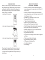
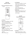
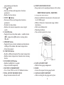
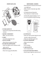
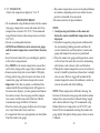
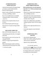
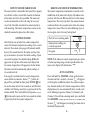
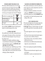
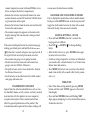
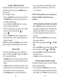
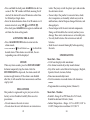
Wireless Rain and
Temperature Monitor
RG1736
User Manual
Table of Contents
Introduction
Product Overview
Remote Rain Gauge
Remote Sensor
Before You Begin
Battery Installation
Remote Temperature Sensor
Main Unit
Low Battery Warning
How To Use the Table Stand
Getting Started
Remote and Indoor Temperatures
Auto-Scanning
Checking Remote Rainfall Data
Maximum and Minimum Temperature
Lost Communication
Transmission Collision
Calendar and Clock Display Modes
Manual Settings
Alarms
Snooze
Precautions
Specifications
FCC Statement
Declaration of Conformity
Standard Warranty Information
2
3
4
9
10
11
13
14
14
14
15
15
16
16
17
18
18
19
20
20
21
23
23
24
26
27
28
INTRODUCTION
Thank you for selecting the Wind & Weather Wireless
Rain and Temperature Monitor. This device monitors
and displays rainfall data along with the indoor/outdoor temperature from up to three remote locations.
In this package you will find:
• One main unit (receiver)
• One remote rain gauge (transmitter)
• One remote temperature sensor (transmitter)
PRODUCT OVERVIEW
MAIN UNIT—FEATURES
• Wireless transmission of the rainfall data from the
remote rain gauge to the main unit up to 100 feet (30
meters) away
• Wireless transmission of the temperature from the
remote temperature sensor to the main unit up to 100
feet (30 meters) away
• Rainfall may be displayed in inches or mm
• Programmable Rain Alarm
• 7 days of rain collection history
• Built-in rain gauge installation level
• Indoor and remote temperature display
• Min/Max Memory for indoor/outdoor temperature
• Hourly, daily and weekly rainfall history
• Monitors temperature in up to 3 remote locations
• Quartz clock with calendar
• Programmable Time Zones
• Day of the week in English, German, French, Spanish
or Italian
• Dual crescendo alarm with snooze
• Programmable Ice Warning Alarm
• Wall mount or desktop option
• Low battery indicator
• LED backlight
Please keep this manual handy as you use your new
item. It contains practical step-by-step instructions,
as well as technical specifications and precautions you
should know.
3
4
FRONT VIEW
(Rain Mode Control Panel)
A. Weather and Time Information in a Three-Line
LCD Display
E. DOWN ( ) button
• Toggles between the rainfall modes—for past hour,
for the past 24 hours, and for the past 7 days
• Decreases all function parameters; press and hold
for rapid decrease
• Enables or disables high rain alarm
• Enforces the remote rain gauge signal search
F. MEMORY button
• Toggles between the rainfall memory modes—for
the past hour, 24 hours, and for the past 7 days
• Clears the memory
REAR VIEW
(Time and Temperature Controls Panel)
B. ALARM button
• Toggles between the rainfall modes—current rainfall
data and rain alarm programming mode
• Activates the high rainfall alarm setting mode
C. MODE button
• Toggles between the rainfall modes—for the past
hour, 24 hours, and for the past 7 days
D. UP ( ) button
• Toggles between the rainfall modes—for the past
hour, 24 hours, and for the past 7 days
• Increases all function parameters; press and hold for
rapid increase
• Enables or disables rain alarm
5
H. MODE button
• Toggles between four clock modes—time with
seconds, time with the day of the week, Time Zone
6
programming and calendar
I . UP ( ) button
• Increases all time and temperature function
parameters
• Enables the time alarms
J . DOWN ( ) button
• Decreases all time and temperature function
parameters
• Disables the time alarms
• Enforces the remote temperature sensor signal
search
K. ALARM button
• Toggles between the alarm modes—weekday alarm
( W), single alarm ( S) and ice warning alarm
(Pre-AL)
L. MEMORY button
• Toggles between current, minimum and maximum
readings of the indoor and remote temperatures
• Clears the memory
M. CHANNEL button
• Recalls a different channel of the remote temperature
• Enables remote temperature channels auto scanning
feature
N. SNOOZE/LIGHT button
• Enables backlight for 5 seconds
• Stops any alarm temporarily
O. BATTERY COMPARTMENT
• Uses 2 (two) UM-3 or AA 1.5V alkaline batteries
P. WALL-MOUNT RECESSED HOLE
• Keeps the main unit on the wall
7
Q. REMOVABLE TABLE STAND
• Keeps main unit in upright position on a flat surface
REMOTE RAIN GAUGE—FEATURES
• Precipitation measurement
• Remote rainfall data transmission to the main unit
via 433 MHz signal
• 100 feet (30 meters) transmission range without
interference
• Built-in installation level
• Mounting hardware
• Non-corrosive protective screen
A. RAIN GAUGE BUCKET
• Holds all rain gauge components
B. KNOB
• Secures the top on the rain gauge bucket
C. RAIN GAUGE BUCKET FEET
• Allow securing the rain gauge on its place
8
REMOTE RAIN GAUGE
D. FUNNEL-SHAPED TOP
• Contains battery compartment and rainfall counting
electronics
E. BATTERY COMPARTMENT
• Holds 2 (two) AA-size batteries
F. SCREWS
• Secure battery compartment cover
G. BUILT-IN LEVELER
• Allows leveling rain gauge on the surface
H. BUCKET SEE-SAW MECHANISM
• Collects the rainfall in one of its containers and selfempties once full
I. PROTECTIVE SCREEN
• Protects the rain gauge funnel from debris
9
REMOTE SENSOR—FEATURES
• Remote temperature transmission to the main unit
via 433 MHz signal
• 100 feet (30 meters) transmission range without
interference
• LCD display of measured temperature
• Three transmission (3) channels selection
• Selection of the temperature display in °C or °F
• Case can be wall mounted using built-in hanger
A. LED INDICATOR
• Flashes once when the remote temperature sensor
transmits a reading to the main unit
• Flashes twice when battery power is low
B. BATTERY COMPARTMENT
• Holds two AA-size batteries
C. RESET
• Resets all readings
D. CHANNEL SWITCH
• Selects the desired channel
E. WALL-MOUNT RECESSED OPENING
• Keeps the remote temperature sensor on the wall
10
F. °C/ °F SELECTOR
• Selects the temperature display in °C or °F
BEFORE YOU BEGIN
• We recommend using alkaline batteries for the remote
rain gauge, temperature sensor and main unit when
temperatures are above 32°F (0°C). We recommend
using lithium batteries when temperatures are below
32°F (0°C).
• Do not use rechargeable batteries.
• ALWAYS install batteries in the remote rain gauge
and the remote temperature sensor before the main
unit.
• Insert batteries before first use, matching the polarity
in the battery compartment.
• Press RESET in the remote temperature sensor after
each battery change with a paper clip or similar tool.
• Remove protective plastic screen from LCD display.
• During initial setup, place the main unit close to the
remote rain gauge and remote temperature sensor.
• Important: Only after reception is established (the
remote rainfall data and temperature will appear on
the main unit’s display), you may position and mount
the remote sensors (the rain gauge and the temperature sensor) and the main unit within the effective
transmission range of 100 feet (30 meters).
• Place the remote rain gauge outdoors on a level, open
area, away from walls, fences and trees.
• It is important that excess precipitation can freely flow
from the remote rain gauge.
11
• The remote temperature sensor can be placed indoors
or outdoors, depending on the area where the temperature is intended to be measured.
•The main unit must be placed indoors.
NOTE:
1. Avoid pressing any buttons on the main unit
before the remote rainfall and temperature data is
displayed.
2. The effective operating range may be influenced by
the surrounding building materials and how the
receiver (main unit) and transmitters (remote rain
gauge and temperature sensor) are positioned.
3. Place the remote rain gauge and temperature sensor
so that it faces the main unit (receiver), minimizing
obstructions such as doors, walls, and furniture.
4. Though the remote temperature sensor is weather-resistant, it should be placed away from direct sunlight,
rain, or snow. The best suggested location for the
remote temperature sensor for outdoors is under an
eave on the north side of the building.
NOTE: When temperatures fall below freezing, the
batteries in the remote rain gauge and outdoor remote
temperature sensor may have reduced voltage supply
and a shorter effective range. We recommend using
lithium batteries at temperatures of 32°F (0°C) and
below. We also recommend covering the remote rain
gauge tightly with plastic during snow storms or move
it indoors.
12
BATTERY INSTALLATION—
REMOTE RAIN GAUGE
• Unlock the funnel-shaped top by turning both knobs
on the sides in a counter-clockwise direction.
• Remove the funnel-shaped top.
• Remove 7 small screws from the battery compartment
cover using a small Phillips screwdriver.
• Insert 2 “AA” size alkaline batteries (not included),
matching the polarities as shown in the battery
compartment.
• Replace the battery compartment door and secure
the screws.
• Insert the funnel-shaped top into the rain gauge
bucket and secure it into place by turning the knobs
clockwise.
RAIN GAUGE PLACEMENT TIPS
• Make sure that the remote rain gauge is level—check
if the ball bearing inside the bucket is at the midpoint
of the leveler.
• Place the protective screen over the top to protect the
rain gauge from debris.
• Mount the rain gauge using mounting hardware
provided.
• Make sure the rain gauge is in open area where precipitation falls directly into the gauge’s bucket, ideally
2–3 feet above the ground.
13
BATTERY INSTALLATION—
REMOTE TEMPERATURE SENSOR
NOTE: Install the batteries; select the channel and
temperature in °C or °F before mounting the remote
temperature sensor.
• Remove the screws from the battery compartment
with a small Phillips screwdriver.
• Set the channel. The switch is located in the battery
compartment. Channel 1 is typically selected if only
one remote sensor is being used.
• Install 2 “AA” size alkaline batteries (not included)
matching the polarities shown in the battery compartment.
• Replace the battery compartment door and secure
the screws.
• Secure remote temperature sensor in the desired
location.
BATTERY INSTALLATION—
MAIN UNIT
• Open the battery compartment door.
• Install 2 “AA” size batteries matching the polarity as
shown in the battery compartment.
• Replace the battery compartment door.
LOW BATTERY WARNING
A low-battery indicator
will appear on the remote
rainfall reading line and the indoor or remote temperature reading line of the main unit, warning that the
corresponding batteries need replacement.
14
HOW TO USE THE TABLE STAND
The main unit has a removable table stand that supports
it on the flat surface. Attach table stand to the bottom
of the main unit in the slots provided. The main unit
can also be mounted on the wall using the recessed
screw hole. The table stand must be removed prior to
wall mounting. The remote temperature sensor can be
similarly mounted or placed on a flat surface.
GETTING STARTED
After batteries are installed, the remote temperature
sensor will transmit temperature readings at 45-second
intervals. The remote rain gauge will transmit rainfall
data at 183-second intervals. The main unit may take
up to two minutes to receive the initial readings. Upon
successful reception, the rainfall reading (0.00) will
appear on the top line of the main unit’s display and
the remote temperature will appear on the line below.
The main unit will automatically update readings at
45-second intervals.
If no signal is received from the remote temperature
sensor within two minutes, dashes [ ] will be displayed. Press and hold the front panel DOWN ( ) button on the main unit for two seconds or until the Rain
symbol starts flashing, to initiate a signal search for the
remote rainfall. Press and hold the back panel DOWN
( ) button on the main unit for two seconds to initiate
a signal search for the remote temperature.
15
REMOTE AND INDOOR TEMPERATURES
The remote temperature information is located on the
middle line of the main unit’s display. The indoor temperature with the icon IN is located next to the remote
temperature. The wave icon above the remote channel
number indicates the reception status from the remote
temperature sensor. There are three following types of
the reception status that may be displayed:
The Unit is in searching mode
Temperature readings are
securely registered
No signal
NOTE: If the indoor or remote temperature goes above
or below operating range stated in specifications, the
main unit’s display will show dashes “ ”.
AUTO-SCANNING
Press and hold the CHANNEL button on the back of
the main unit for 2 seconds—the icon “ ” will appear
on the display’s middle line below the remote temperature channel number. All 3 remote temperatures will be
displayed one-by-one automatically for 4 seconds each
in the following sequence: Channel 1, Channel 2 and
Channel 3. To exit from scanning mode, press and hold
the CHANNEL button (on the back) for 2 seconds, and
the icon “ ” will disappear, returning the main unit to
the default display mode.
16
CHECKING REMOTE RAINFALL DATA
The remote rainfall information line is located on the
top line of the main unit’s display. The rain icon “ ” is
located to the left of the rainfall reading and indicates
the reception status from the remote rain gauge. There
are three types of reception status that may be displayed:
The Unit is in searching mode
Rainfall readings are
securely registered
No signal
Press and hold the MODE button on the front panel to
display the rainfall reading in inches or mm.
RAINFALL HISTORY
The rainfall history records will be automatically stored
in the memory of the main unit. There are three historical records that may be displayed—the past hour, past
day, and past week.
• To display any of available rainfall history reading,
use any button on the front panel except the ALARM
button. The display sequence is: LAST HOUR, LAST
24 HOURS, and LAST 7 DAYS.
• To clear the memory, press and hold MEMORY button
on the front panel for two seconds and all previously
stored readings will be erased (all the historical records
will display a default reading 0.00).
17
MAXIMUM AND MINIMUM TEMPERATURE
The maximum and minimum record of the indoor and
remote temperatures will be automatically stored in the
memory of the main unit.
• To display the minimum, maximum, or the current
reading, press MEMORY button on the back panel.
• To clear the memory, press and hold MEMORY button
on the back for two seconds and all previously stored
readings will be erased.
LOST COMMUNICATION
If the main unit display line for the remote temperature
sensor reading goes blank, press and hold the back
DOWN ( ) button for 2 seconds to begin a new signal
search. If the signal still isn’t received, please make sure
that:
• The remote temperature sensor is in its proper location.
• The distance between main unit and remote temperature sensor is not over 100 feet (30 meters).
• The path between units is clear of obstacles. Shorten
the distance if necessary.
• Fresh batteries are installed correctly in both remote
temperature sensor and main unit.
If there is no reception, please perform the following
steps:
• Bring the main unit and remote temperature sensor
close together.
• Remove four (4) small screws from the back of the
18
remote temperature sensor with small Phillips screwdriver, and open the battery compartment.
• Remove the batteries and reinstall them in the same
manner. Remote sensor LED indicator will flash showing transmission of the signal.
• Remove the batteries from the main unit and reinstall
them in the same manner.
• The remote temperature appears on the main unit’s
display showing that transmission is being received
successfully.
If the main unit display line for the remote rain gauge
reading goes blank, press and hold the front DOWN
( ) button for 2 seconds to begin a new signal search. If
the signal still isn’t received, please make sure that:
• The remote rain gauge is in its proper location.
• The distance between main unit and remote rain
gauge is not over 100 feet (30 meters).
• The path between units is clear of obstacles. Shorten
the distance if necessary.
• Fresh batteries are installed correctly in both remote
rain gauge and main unit.
TRANSMISSION COLLISION
Signals from the other household devices such as wireless doorbells, home security systems, and entry control,
may interfere with this product or cause temporary
reception interruption. This is normal and will not
affect the general performance of the product. The
transmission and reception of the remote readings will
19
resume once the interference subsides.
CALENDAR AND CLOCK DISPLAY MODES
Date is displayed in month-date or date-month format.
Each press of the MODE button on the back panel will
toggle the clock modes between the time with seconds,
time with the day, time zone and a calendar.
MANUAL SETTINGS—CLOCK
• Press and hold MODE button for 3 seconds: the
language letters will flash.
• Press UP ( ) or DOWN ( ) to change flashing
letters.
• After the first value is set, press MODE button again
to move to the next value.
• Continue setting temperature in Celsius or Fahrenheit,
year, month, date, calendar format, 12 or 24 hour time
format, hour and minutes.
• Press MODE for the last time to return to the default
mode (time of day with seconds) after the last parameter is set.
TIME ZONE
• Select Time Zone setting mode by pressing MODE
button until the word “ZONE” appears to the left of
time display.
• Press and hold MODE button until flashing“0:00”
digits appear prompting to set the desired time zone in
30 minutes intervals.
20
ALARMS—HIGH RAIN ALARM
The high rain alarm for the past 24 hours can be set and
displayed at any time by pressing ALARM button on
the front panel.
To set the high rain alarm,
• Press the ALARM button on the front panel until the
“ALARM HI” appears on the upper right corner of
the rainfall information line.
• Press and hold the ALARM button for 2 seconds or
until the rainfall data digits flash.
• Enter the rainfall amount you want to set the rainfall
alarm for using the front panel UP ( ) or
DOWN ( ).
• Press the ALARM button again to confirm that the
high rain alarm is set. Leave in Alarm Hi mode until
alarm has sounded.
NOTE: Press and hold the MODE button on the front
panel to display the rainfall reading in inches or mm.
TIME ALARMS
The Wireless Rain Monitor has three available time
alarms—Weekday alarm ( W), Single alarm ( S) and
Ice Warning Alarm (Pre-Al).
• If Weekday alarm is activated, it will sound at the set
time and the alarm icon will flash Mondays through
Fridays.
• If Single day alarm is activated, it will sound at the set
time and the alarm icon will flash only for this specific
day and will not activate on subsequent days.
• If Ice Warning alarm is activated, in will sound at
21
the set time and alarm icon will flash if the remote
temperature for Channel One (1) reaches 35.6°F
(+2°C) and below.
NOTE: Ice Warning Alarm can be set only if one or
both of the Weekday or Single alarm are programmed.
SETTING WEEKDAY & SINGLE DAY ALARMS
• Press ALARM button once to enter into the alarms
setting mode. The default alarm is a Weekday alarm.
The abbreviation “OFF” with a letter “ W” next
to it will be displayed if the alarm has not been set
previously.
• Press and hold the ALARM button for two seconds.
The hour digit will flash.
• Enter the hour using back panel UP ( ) or DOWN
( ).
• Press the ALARM again. The minute digits will flash.
• Enter the minutes using UP ( ) or DOWN ( ).
• Press the ALARM button again to confirm that the
weekday alarm is set.
• Set Single day alarm in the same manner.
SETTING THE ICE WARNING ALARM
If Weekday or Single day alarm is set, the Ice Warning
Alarm can be programmed.
• Press the back panel ALARM button once to enter
into the Ice Warning Alarm setting mode. The abbreviation “OFF” with a “PRE-AL” next to it will show.
22
• Press and hold the back panel ALARM button for two
secon ds. The “30” number will flash, meaning that if
selected, the alarm will sound 30 minutes earlier than
the Weekday or Single alarm.
• Enter the desired minutes from 15 to 90 minutes in 15
minutes intervals, using UP ( ) or DOWN ( ).
• Press back panel ALARM button again to confirm and
exit from the alarm setting mode.
ACTIVATING THE ALARM
• Press ALARM ON/OFF button to enter into the
alarms mode.
• Press DOWN ( ) to activate or UP ( ) to deactivate
desired alarm. When alarms are activated, the corresponding icons will be displayed.
SNOOZE
When any alarm sounds, press the SNOOZE/LIGHT
buttonto temporarily stop the alarm. After the
SNOOZE/LIGHT is depressed, the alarm sound will
resume in eight minutes. If the alarm is not disabled
after that, it will sound for four more minutes and then
stop by itself.
PRECAUTIONS
This product is engineered to give you years of satisfactory service if handled carefully. Here are a few
precautions:
• Do not immerse the units in water.
• Do not clean the units with abrasive or corrosive ma23
terials. They may scratch the plastic parts and corrode
the electronic circuits.
• Do not subject the product to excessive force, shock,
dust, temperature, or humidity, which may result in
malfunctions, shorter lifespan, damaged batteries, and
damaged parts.
• Do not tamper with the units internal components.
Doing so will invalidate the warranty and may cause
damage. These units contain no user-serviceable parts.
• Use only fresh batteries. Do not mix new and old
batteries.
• Read the user’s manual thoroughly before operating
the units.
SPECIFICATIONS
Main Unit—Time
•12/24 hour display in hh: mm format
•Date format: month-day or day-month format
• Day of the week is selectable in five languages (English,
Spanish, French, German, Italian)
•Time zone manual adjustment
• Dual two-minute crescendo alarms with 8 minutes
snooze
•Programmable ice warning alarm (Channel 1)
Main Unit—Weather
• Rainfall—Range: 0 to 1999.9mm; 0 to 78.74 inch;
Rainfall resolution: 0.04 inch (1mm)
• Indoor Temperature—Range: -5.0° to +50.0°C; 23.0° to
122.0°F; Temperature resolution: 0.1°C/0.2°F
24
• User-selectable (°F or °C) temperature display
• LED backlight
• Low battery indicator
• Wall Mount or Desktop option
Dimensions
• Main unit: 2¾"W x 5½"H
• Remote sensor: 2¼"W x 4"H
• Remote rain gauge: 6½"W x 7"H
Remote Rain Gauge—Remote Rainfall Data
• Operating range: -5.0° to +50.0°C; 23.0° to 122.0°F
• RF transmission frequency: 433 MHz
• RF transmission range: maximum 100 feet (30 meters)
• Rainfall transmission cycle: approximately 183 seconds
FCC STATEMENT
This device complies with Part 15 of the FCC Rules.
Operation is subject to the following two conditions:
(1) This device may not cause harmful interference, and
(2) This device must accept any interference received,
including interference that may cause undesired operation.
Remote Temperature Sensor—Remote Temperature
• Operating range with alkaline batteries: -20.0° to
+70.0°C; -4.0° to +158°F
• Operating range with lithium batteries: -38.8° to
+70.0°C; -38.0° to +158°F
• Temperature resolution: 0.1°C/0.2°F
• Low battery indicator
• RF transmission frequency: 433 MHz
• Maximum number of remote sensors: 3 (1 included)
• RF transmission range: maximum 100 feet (30 meters)
• Temperature transmission cycle: approximately 45
seconds
Power
• Main unit: 2 AA size (UM-3) 1.5V batteries (not incl)
• Remote sensor: 2 AA size (UM-3) 1.5V batteries (not
included)
• Remote rain gauge: 2 AA size (UM-3) 1.5V batteries
(not included)
25
Warning: Changes or modifications to this unit not
expressly approved by the party responsible for compliance could void the user’s authority to operate the
equipment.
NOTE: This equipment has been tested and found to
comply with the limits for a Class B digital device, pursuant to Part 15 of the FCC Rules. These limits are designed to provide reasonable protection against harmful
interference in a residential installation. This equipment
generates, uses, and can radiate radio frequency energy
and, if not installed and used in accordance with the
instructions, may cause harmful interference to radio
communications.
There is no guarantee that interference will not occur
in a particular installation. If this equipment does cause
26
harmful interference to radio or television reception,
which can be determined by turning the equipment
off and on, the user is encouraged to try to correct the
interference by one or more of the following measures:
• Reorient or relocate the receiving antenna.
• Increase the separation between the equipment and
receiver.
• Connect the equipment into an outlet on a circuit different from that to which the receiver is connected.
• Consult the dealer or an experienced radio/TV technician for help.
STANDARD WARRANTY INFORMATION
This product is warranted from manufacturing defects
for one year from date of retail purchase. It does not
cover damages or wear resulting from accident, misuse,
abuse, commercial use, or unauthorized adjustment and
repair. Note that online product registration is required
to ensure valid warranty protection.
DECLARATION OF CONFORMITY
We
Name: Hideki Electronics, Inc.
Address: 7865 SW Mohawk, Tualatin, OR 97062
Telephone No.: 1-503-612-8395
declare that the product
Product No.: TC150
Product Name: Wireless Rain Gauge
Manufacturer: Hideki Electronics Ltd.
Address: Unit 2304-06, 23/F Riley House, 88 Lei Muk
Road, Kwai Chung, New Territories, Hong Kong
is in conformity with Part 15 of the FCC Rules. Operation is subject to the following two conditions:
(1) This device may not cause harmful interference.
(2) This device must accept any interference received,
including interference that may cause undesired operation.
Please direct all returns to the place of the original
purchase. Please retain your original receipt as you may
be asked to provide a copy for proof of purchase.
27
28
Should you require assistance with this product and its
operation, please contact Wind & Weather Customer
Service at 1-877-255-3700.
© 2006 Wind & Weather. All Rights Reserved. All user
manual contents and information are subject to change.