1
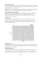
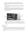
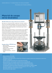
06.09
product manual
H-1322B
Marshall and TSR
Compression Machine
TABLE OF CONTENTS
Introduction. . . . . . . . . . . . . . . . . . . . . . . . . . . . . . . . . . . . . . . . . . . . . . . .
2
General Information . . . . . . . . . . . . . . . . . . . . . . . . . . . . . . . . . . . . . . . . .
Inspection . . . . . . . . . . . . . . . . . . . . . . . . . . . . . . . . . . . . . . . . . . . . . . . . . . .
Physical Specification . . . . . . . . . . . . . . . . . . . . . . . . . . . . . . . . . . . . . . . . . .
Power Supply . . . . . . . . . . . . . . . . . . . . . . . . . . . . . . . . . . . . . . . . . . . . . . . .
Power Cord. . . . . . . . . . . . . . . . . . . . . . . . . . . . . . . . . . . . . . . . . . . . . . . . . .
nnmm
Fuses . . . . . . . . . . . . . . . . . . . . . . . . . . . . . . . . . . . . . . . . . . . . . . . . . . . . . .
2
2
3
3
3
3
Initial Installation . . . . . . . . . . . . . . . . . . . . . . . . . . . . . . . . . . . . . . . . . . .
3
Operation . . . . . . . . . . . . . . . . . . . . . . . . . . . . . . . . . . . . . . . . . . . . . . . . .
Control Panel . . . . . . . . . . . . . . . . . . . . . . . . . . . . . . . . . . . . . . . . . . . . . . . .
Preset Speed of Platen . . . . . . . . . . . . . . . . . . . . . . . . . . . . . . . . . . . . . . . . .
Direction of Travel . . . . . . . . . . . . . . . . . . . . . . . . . . . . . . . . . . . . . . . . . . . .
Maximum Travel Limit Switches . . . . . . . . . . . . . . . . . . . . . . . . . . . . . . . . . .
Chart Scales . . . . . . . . . . . . . . . . . . . . . . . . . . . . . . . . . . . . . . . . . . . . . . . . .
Maximum Load . . . . . . . . . . . . . . . . . . . . . . . . . . . . . . . . . . . . . . . . . . . . . . .
Flow Measurement . . . . . . . . . . . . . . . . . . . . . . . . . . . . . . . . . . . . . . . . . . . .
Running a Test. . . . . . . . . . . . . . . . . . . . . . . . . . . . . . . . . . . . . . . . . . . . . . . .
3
3
3
4
4
4
4
4
4
Calibration . . . . . . . . . . . . . . . . . . . . . . . . . . . . . . . . . . . . . . . . . . . . . . . . .
5
Maintenance . . . . . . . . . . . . . . . . . . . . . . . . . . . . . . . . . . . . . . . . . . . . . . .
6
General Warnings . . . . . . . . . . . . . . . . . . . . . . . . . . . . . . . . . . . . . . . . . . . . 7
Saftey Warnings. . . . . . . . . . . . . . . . . . . . . . . . . . . . . . . . . . . . . . . . . . . . . . . 7
Electrical Warnings . . . . . . . . . . . . . . . . . . . . . . . . . . . . . . . . . . . . . . . . . . . . 7
Important Notice . . . . . . . . . . . . . . . . . . . . . . . . . . . . . . . . . . . . . . . . . . . . 7
Updated Products . . . . . . . . . . . . . . . . . . . . . . . . . . . . . . . . . . . . . . . . . . . . 7
Fitness for Application . . . . . . . . . . . . . . . . . . . . . . . . . . . . . . . . . . . . . . . . . 7
Parts Drawing . . . . . . . . . . . . . . . . . . . . . . . . . . . . . . . . . . . . . . . . . . . . . . . 8
Notes . . . . . . . . . . . . . . . . . . . . . . . . . . . . . . . . . . . . . . . . . . . . . . . . . . . . . . 9
1
Introduction
The Humboldt H-1322B, Marshall and TSR Compression Machine, is a state-of-the-art
apparatus specifically designed for Marshall and TSR testing. These tests can be used
to evaluate the relative quality of materials, as well as generate input for pavement
design or pavement evaluation and analysis. The microprocessor-based system
incorporates a 16-bit Analog to Digital (A to D) converter with chart recorder output and
RS232 computer connection capabilities. The system automatically tests and records
Marshall stability and plastic flow of Bituminous mixture on one chart with an accuracy
to less than 1 percent over the total range, eliminating operator error in dial readings
and manual recording of data.
Meets ASTM D6927, D4123-82; AASHTO T245, T283, BS 598-107.
Overall dimensions are: 36" x 18" x 38-1/2"H (914 x 457 x 978mm).
Shipping wt. 250 lbs. (113.6 kg)
Features include:
• The Marshall and TSR Compression Machine has a total
frame capacity of 10,000 lb (45kN).
• Stress is measured with a supplied S-Type load cell.
• The apparatus features an AC single-speed motor with an
operating rate of 2 in/min or (50.8mm/sec.), and a built-in yt chart
recorder, for monitoring load vs. rate of compression.
• The 16-bit Analog to Digital converter can be connected
directly to a computer or serial printer for live data monitoring.
• The apparatus automatically detects the peak value, automatically
stops testing procedure upon completion and automatically activates
the chart recorder for a hard copy of the test data.
• Maximum piston travel is 3-1/2" (88mm) with limit switch to
prevent gearbox jams and damages.
General Information
Inspection
Your Marshall & TSR equipment was thoroughly inspected before it was shipped and
should be ready to operate as soon as you have completed the set-up procedure.
Notify Humboldt Mfg. Co. or your local agent and file a claim with any carriers involved
if you find any damage to the machine. Unpack all of the equipment carefully to prevent
loss of small items or manuals.
2
Physical Specification
Net weight: Shipping weight: Overall height: Base dimension: 226 lbs. (110 kg)
266 lbs. (113.6 kg)
39"
35"x18"x10"
Power Supply
110 VAC 60 Hz 1 phase (H-1322B), 975 watts
220 VAC 60 Hz 1 phase (H-1322B.2F), 975 watts
220 V AC 50 Hz 1 phase (H-1322B.5F), 975 watts
Check that your machine has the correct voltage for your local supply.
Power Cord
Your Marshall & TSR Test Machine is fitted with a fused IEC receptacle and
cord with molded vinyl-grounding plug. The cord is made of three conductors:
(American color-coding)
Green
White Black or
Ground (Earth)
Cold (Neutral)
Hot (Live)
(European color coding)
Green /Yellow
Blue Brown Ground (Earth)
Cold (Neutral)
Hot (Live)
Fuses
The Marshall Test Machine uses a slo-blow fuse that is fitted into the rear of
the machine. The replacement part a 5 x 20 mm 10A, 250V ceramic (or glass).
Initial Installation
Remove the packing list and verify that all parts have been received. Normally you
will receive one crate comprised of compression and recorder frame, with calibrated
load cell (HM-2300.100) 10,000lbf capacity (44kN) fastened to it, 100 charts
(H-1322CP), 6 pens, a DB9 serial cable, and this user manual.
Set the machine base up at the place it is to be used in the laboratory and then
check that it is level by placing a spirit level on the platen. If it is not level, adjust the
feet of the machine.
Operation
Control Panel
The control panel is situated on the front right hand side of the machine base.
Recorder range and pen controls are on the recorder's chart plate.
Preset Speed of Platen:
2.00 in/min. (50.80mm/min.)
3
Direction of Travel
It is necessary to ensure that the direction of the platen (up or down) has been
correctly selected. Choosing one of the three switch positions controls the platen
travel direction: Up, Off, or Down.
Note: There is a 4 second delay built in between a change in motor direction to
allow the motor to stop before restarting in the opposite direction.
Maximum Travel Limit Switches
Maximum travel limits up and down are indicated on the control panel with
green and red indicating lights. The machine will stop operation in that
direction and one of the lights will be illuminated. The maximum travel of
the platen is 3.50" (88mm).
Chart Scales
A sample chart is included with these instructions. The vertical axis major
divisions each represent, depending on the range chosen, 500 or 1000
pounds force and the horizontal major divisions each represent .05 inches
of flow (or platen travel).
Maximum Load
The Marshall & TSR Compression Machine is rated a 10,000 lbf (44kN), which
is the load cell range. An automatic, high load cut-off feature stops the machine
at approximately 10,500 lbf.
Flow Measurement
The pen travel in the horizontal axis (flow) direction indicates the flow on the
chart; its speed is exactly correlated with the 2 in./min. platen speed of the
compression machine. The full-scale range on the chart is .5 inches of flow.
4
Running a Test
1. Turn on the rear power switch, install a pen in the holder by turning about
three turns clockwise with light finger pressure only, and place a sheet of chart
paper under the holders.
2.
3. Place the conditioned specimen in the breaking head and onto the
machine platen.
4. Push the Up button that has a 4-second delay to begin pen contact, travel
and loading after which the test proceeds automatically.
Place the lever in the Pen Down position and zero the pen on the chart with
the positioning knobs, placing the pen at the origin of the graduated area of
the chart. This will ensure complete recording initiated by sensing of the load.
Select the load range with the selector switch on the recorder and
place a check in the box for that range on the chart.
5. Upon reaching the stability load or TSR peak, the machine proceeds until
a 5% reduction in load occurs, at which time it stops, waits 4 seconds, then
reverses and goes to the lower limit of down travel.
6. Load the next specimen and repeat Step 4.
7. Upon completion of tests move the recorder lever to the “Load” position
and remove the chart paper.
Important - If a test is incomplete for some reason, reset the processor by turning
off the machine power with the rocker switch on the rear panel.
Calibration
As received, the machine is calibrated to 1% accuracy or better over
the full range.
When it is necessary to check calibration proceed as follows:
CAUTION
IMPORTANT: Press the Down travel switch to lower the platen
to its lower limit of travel as indicated by the red (Ready) light
coming on, then press the red Stop button, which deactivates the
automatic test function.
Use a load ring or load cell as a reference gage to check
calibration by placing it directly under the machine's load cell
(in place of the Marshall or TSR breaking head).
Remove the Crank hole plug (left side of casing).
5
Using a ½" hex socket on a 3/8" drive ratchet, connect to the
internal male hex shaft and crank counter clockwise to raise the
platen and apply load to the reference gage and the machine’s
load cell.
Starting from the chart origin, observe the recorder's pen position
and check it against the reference gage reading for each 1000 lbf
of load applied.
If an adjustment other than a zero shift is needed, remove the
recorder from the chassis leaving the cables connected and from
the picture below find potentiometer R231 (for the Y axis). With
a small, plastic screw driver turn the pot to increase or decrease
the gain as required.
R131
R231
Top End
Calibration of the Flow or X axis is accomplished by measuring the platen
travel with a rule while keeping time with a stop watch (usually 1/2" in 15
seconds is the measured distance and time check) while observing the chart
reading. If the travel is not within .50" +/- .04" on the chart adjust the gain
using pot R131.
Maintenance
The machine and transducers should be kept clean and the machine should not be
over lubricated. Light oiling with synthetic instrument oil at most is required on
exposed spindles and threads; the jack and gear box are serviced with a premium
wheel bearing grease such as Pennzoil 707L Lubriplate Grease applied thru the grease fitting no more than annually, or when an indication of power train friction
appears.
6
General Warnings
Safety Warnings
Operators should take care to operate this machine under the
maximum load restrictions. The machine is programmed at the factory
to provide safety shutdown if the upper or lower maximum travel is
exceeded as well as if the upper instrument calibration is exceeded.
Electrical Warnings
Typically, there is no reason for the operator to open the machine.
However, if the customer’s engineers attempt to change settings to the
circuit board connected to the back panel, the machine must always be
unplugged before this operation. Unplugging the internal connection to
the back panel circuit board while the machine is under power will
result in permanent damage to the circuit board.
IMPORTANT NOTICE
The information contained herein is supplied without representation or
warranty of any kind. Humboldt MFG. Co. therefore assumes no
responsibility and shall have no liability, consequential or otherwise, of
any kind arising from the use of the described equipment contained in
this manual.
Updated products
The manufacturer reserves the right to change or modify product
design or construction without prior notice and without incurring any
obligation to make such changes and modifications on products
previously or subsequently sold.
Fitness for application
The manufacturer makes no recommendations or claims regarding
fitness for applications other than the specific tests as defined in this
User Guide.
7
8
Notes
9
Warranty
Humboldt Mfg. Co. warrants its products to be free from defects in material or
workmanship. The exclusive remedy for this warranty is Humboldt Mfg. Co.,
factory replacement of any part or parts of such product, for the warranty of this
product please refer to Humboldt Mfg. Co. catalog on Terms and Conditions
of Sale. The purchaser is responsible for the transportation charges. Humboldt
Mfg. Co. shall not be responsible under this warranty if the goods have been
improperly maintained, installed, operated or the goods have been altered or
modified so as to adversely affect the operation, use performance or durability
or so as to change their intended use. The Humboldt Mfg. Co. liability under
the warranty contained in this clause is limited to the repair or replacement of
defective goods and making good, defective workmanship.
.
U.S.A. Toll Free: 1.800.544.7220
Voice: 1.708.456.6300
Fax: 1.708.456.0137
Email: [email protected]