1
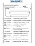
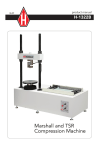
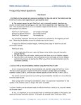
08.09
product manual
H-4210A
Portable, Static Cone
Penetrometer
Portable, Static Cone Penetrometer
Information
The H-4210A Static Cone Penetrometer is an unparalleled device for measuring soil
consistency. It is specifically designed for use in fine grained, soft soils to depths as much
as 30 feet. The basic unit is totally self contained, weighs 5 Ib, and is set up for a 2-ft
maximum depth. It is intended to be operated by one person and requires no auxiliary
equipment. The device is extremely rugged and is built for day-in, day-out use.
Practical Applications
•
Rapid selection of locations for field density tests
•
Evaluating backfills in trenches and behind walls
•
Light foundation investigations
•
For rapid correlation of field CBR tests
•
Earthwork control for embankments
•
Muck and soft soil probes
•
Probing shallow marine deposits
•
Probing beneath existing shallow foundations
•
Pavement subgrade evaluation
Operating Instructions
Dual rods enable the cone stress to be measured directly. Soil friction on the outer rod
does not influence the reading. Depending upon the application, either the maximum
bearing for an increment of push or the least bearing for an increment can be reported.
If you were investigating for soft spots, you would take the least reading. In typical use,
you would force the cone into the soil 6 inches, retract the cone slightly until the gauge
reads zero, then advance an additional 6 inch increment. If you meet with refusal, the
cone can be removed and the hole opened with a hand auger to permit a continuation
of measurements against depth.
The tool has been designed to allow a maximum force of 250 Ibf to be applied,
somewhat more than the average weight of an operator. The unit can be operated in a
vertical or horizontal position. The cone tip has an included angle of 60°. The cone has a
section area of 1.5 cm2. The maximum total bearing (Qc) is 70 kg/cm2.
The H-4210A penetrometer assembly comes standard with a 2-ft Inner/Outer “starter”
rod assembly. If you wish to use extensions, it will be necessary to purchase the
H-4210E.2A, 2-ft “extension” Inner/Outer Rod assembly.
Note: Starter Inner Rods are 0.875 inch longer than the similar-looking Extension Inner
Rods (i.e., the overall length for the 2-ft Starter Inner Rods is 24.875 in. and for the
Extension Inner Rods is 24 in; the Starter and Extension Outer Rods have the same
length).
Simple determination of approximate unconfined compression strength, standard
penetration test "N" and CBR values can be derived from the cone index.
How To Use the Cone Index
The reading (Qc) is in kg/cm2 which is essentially equal to ton/ft2. The cone index (Qc) is
read directly. The correlation between the cone index and soil constants is not absolute.
Generally, the following results have been determined through extensive field use of the
unit. Further verification of correlation in your local soil types is essential. Humboldt Mfg.
accepts no liability for the accuracy of the suggested correlations.
Standard Penetration
Strength and Cohesion
CBR Value (1 %)
Test “N” Value
Qu - Unconfined compression (kg/cm ) Qc = (2.5 to 3.3) CBR
Qc = 4 “N”
c - Cohesion (kg/cm2 )
2
Uniform clay and silty clays: Qc = 5 Qu
Qc = 10 c
Clayey Silts:
Qc = (10 to 20) Qu
Qc = (20 to 40) c
Unpacking
As you unpack your Static Cone Penetrometer, check for the following items by referring
to the enclosed parts list and drawings:
Item 1 - Head Assembly**
Item 18 - Cone Assembly
Item 8 or 11 - Outer/Inner Rod Assembly
H-4210A User Manual
Assembly and adjustment of your Penetrometer will require the above items, as well as
a 7/16" open wrench and a medium flat-blade screwdriver (not supplied). You will also
need a small wooden block or board or a hard rubber mat to check the instrument.
** The gauge installed in the Head Assembly is glycerin filled. The glycerin acts as a
shock-absorber and may have a "bubble" which is usually visible and is normal.
Assembly and Adjustment
To assemble your Penetrometer, screw the Cone Assembly (Item 18) into the Outer/Inner
Rod Assembly (Item 8 or 11) and tighten with a wrench. Next, screw this sub-assembly
into the Head Assembly (Item 1) and tighten with a wrench. Check to be sure the system
is properly adjusted by pressing the Penetrometer down onto a board or rubber mat.
The needle on the gauge should move as soon as pressure is applied . After pressure is
removed , the needle should return to zero. If the gauge does not respond when force
is applied to the Cone, turn the brass Adjustment Screw (Item 4) in the Head Assembly
(Item 1) clockwise until the needle moves. This is the zero point to the system.
If the gauge will not return to zero, turn the brass Adjustment Screw counter clockwise
until the needle returns to zero.
You should now be ready to use your Static Cone Penetrometer.
Maintenance
Your Cone Penetrometer is a ruggedly-designed device intended to tolerate a reasonable
amount of field abuse.
The most critical requirement is keeping foreign matter outside the annulus between the
Inner and Outer Rods. It is recommended that a drop or two of lightweight machine oil
be applied frequently to the annulus. (A schedule of every 2-3 days is recommended if
the unit is being used daily). The Inner Rod is a surface-ground stainless steel rod which
will not rust. The Outer Rod is made of a high-strength alloy steel tubing which is subject
to ru sting. The machine oil will curb that tendency.
Always make an attempt to apply a normal (vertical or in-line) thrust on the assembly as it
is pushed into the ground. A severe horizontal thrust coupled to a normal, vertical thrust
could produce a situation in which the rods could be bent. It is infinitely easier to avoid
bending the rod than to straighten the rod.
Periodically inspect the Cone Assembly. If the Cone Assembly has suffered excessive
wear, it needs to be replaced. The original diameter of the Cone is 0.544". When the
outer diameter is reduced to a diameter of 0.520", it is recommended that the point be
replaced.
Repair
If you notice that your penetrometer is leaking or will not hold pressure, you will need to
replace the “0 ” ring (Item 5) on the Adjustment Screw (Item 4) and/or the piston (Item 6).
Adjustment Screw“0” Ring Replacement:
1. Remove the Outer Rod Assembly (Item 8 or 11) from the Head Assembly (Item 1).
2. Clamp the Head Assembly in a vise with the brass Adjustment Screw pointing up.
3. Remove the Adjusting Screw from the Head Assembly and discard the “0” ring.
4. Install the new “0” ring, being careful not to damage it.
5. Fill the reservoir with automatic transmission oil until flush with the top.
6. Drop in the Adjustment Screw and thread clockwise until flush with the top. (Note:
Oil will run out during this step preventing air from being trapped inside).
7. Screw the Outer Rod Assembly into the Head Assembly.
8. Continue to screw the brass Adjustment Screw clockwise until the needle on the
gauge begins to move. At this time, back off the screw until the gauge reads zero.
9. The Static Cone Penetrometer is now ready for use.
Piston “0” Ring Replacement:
1. Remove the Inner/Outer Rod Assembly (Item 8 or 11) from the Head Assembly
(Item 1).
2. Remove the Insert (Item 7) from the Head Assembly. (Note: For this procedure, you
will need a 3/8"- 16 x 2" long bolt and nut. Screw the bolt and nut into the insert
and use the nut to jam the bolt; this will prevent the bolt from backing out of the
Insert. Now, use the bolt to screw the Insert out of the Head. This procedure can be
made easier if the Head Assembly is slightly heated at the Insert. (Leaving the nut
and bolt in the Insert will facilitate reassembly).
3. Remove the Adjustment Screw (Item 4) and drain the oil from the unit.
4. Using a long screw driver, or similar tool, press the Piston (Item 6) out of the
bottom of the Head.
5. Replace the “0” ring (Item 5), being careful not to damage it.
6. Replace the Piston from the bottom of the Head, with the drilled hole facing
outward.
CAUTION: The Piston must be inserted from the BOTTOM of the Head to prevent
damage to the “0” ring and should not be pushed above the Gauge opening.
7. Reinstall the Insert in the bottom of the Head Assembly, using the bolt and nut.
NOTE: Loctite® thread fastener is recommended to insure the Insert does not
unthread during use.
8. Using a long screw driver or similar tool, press the Piston from the top (or
Adjustment Screw end) of the Head down against the Insert, being careful not to
damage the bore.
9. Refill the Head with Automatic Transmission oil until flush with the top.
10. Drop in the brass Adjustment Screw and thread clockwise until flush with the top.
NOTE: Oil will run out during this step, preventing air from being trapped inside.
11. Screw the Outer Rod Assembly into the Head Assembly, watching the needle of
the Gauge. If the Gauge needle begins to move, back out the Adjustment Screw to
allow the excess oil to escape.
CAUTION: Failure to allow excess oil to escape will over-pressurize and damage
the Gauge.
12. Once the Outer Rod Assembly is tight, the Adjustment Screw is turned clockwise
until the needle on the Gauge begins to move. At this time, back off the Screw
until the Gauge reads zero.
Item
Description
1
Head Assembly
(includes items 2-7, 19 & 20)
2
Handle (2 required)
3
Body
4
Adjustment Screw
5
“O” ring (2 required)
6
Piston
7
Insert
8
2-ft Starter Rod Assembly
(includes items 9 & 10)
9
2-ft Starter Inner Rod
10
2-ft Outer Rod
11
2-ft Extension Rod Assembly
includes items 12 & 13)
12
2-ft Extension Inner Rod
13
2-ft Outer Rod
14
Cone Assembly
15
Gauge Guard (not shown)
16
Gauge Assembly (not shown)
17
“O” ring Packing Kit (not shown)
(includes 2 each of item 5)
Helpful Hint: Starter Inner Rods are 0.875" longer than
the similar-looking Extension Inner Rods (i.e. 2-ft Starter
Inner Rods are 24.875"OAL. The Extension Inner Rods
are 24" OAL).
4
5
2
2
6
5
3
7
1
9, 12
8,
11
10, 13
14
Warranty
Humboldt Mfg. Co. warrants its products to be free from defects in material or
workmanship. The exclusive remedy for this warranty is Humboldt Mfg. Co., factory
replacement of any part or parts of such product, for the warranty of this product please
refer to Humboldt Mfg. Co. catalog on Terms and Conditions of Sale. The purchaser is
responsible for the transportation charges. Humboldt Mfg. Co. shall not be responsible
under this warranty if the goods have been improperly maintained, installed, operated
or the goods have been altered or modified so as to adversely affect the operation, use
performance or durability or so as to change their intended use. The Humboldt Mfg. Co.
liability under the warranty contained in this clause is limited to the repair or replacement
of defective goods and making good, defective workmanship.
Humboldt Mfg. Co.
875 Tollgate Road
Elgin, Illinois 60123 U.S.A.
U.S.A. Toll Free: 1.800.544.7220
Voice: 1.708.456.6300
Fax: 1.708.456.0137
Email: [email protected]