1
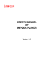
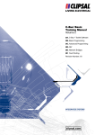
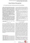
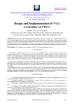
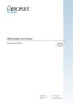
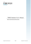
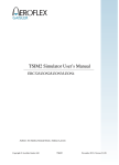
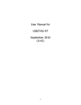
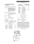
International Conference on Advanced Computing, Communication and Networks’11 Simulation of Vehicular Application using Leon Environment Abhijit S. Titarmare Dinesh V. Padole Research scholar: Department of Electronics & Telecommunication Engineering. G.H.Raisoni College of Engineering Nagpur, India [email protected] Assistant professor: Department of Electronics Engineering. G.H.Raisoni College of Engineering Nagpur, India d v _ p a d o le @ r e d i f f m a il.c o m Abstract: LEON3 is a 32-bit processor core conforming to the IEEE-1754 (SPARC V8) architecture. It is designed for embedded applications, combining high performance with low complexity and low power consumption. TSIM2 is a simulator that can emulate LEON3 based computer systems. It can also emulate user specific system-on-a-chip solutions by means of loadable modules. TSIM2 allows emulation of the LEON3 processor core with a completely user defined memory and I/O architecture. The emulated processor core communicates with the AHB module using an interface similar to the AHB master interface in the real LEON3 VHDL model. The AHB module can then emulate the complete AHB bus and all attached units. This paper presents simulation of vehicular application using LEON3 environment (TSIM2). The application includes wiper control and temperature control of AC in vehicle. Keywords: LEON3 Processor, TSIM2, BCC, SPARC V8 Processor, RT Linux, elf –Snapgear. I. INTRODUCTION Vehicular electronics systems have changed radically over the last two-three decades. Early vehicular electronics systems were made up of switches, wires, relays and controlled motors or lamps. Modern vehicles however incorporate a wide range of sensors and actuators coupled to advanced electronics control system. The main motivation behind this is because of fast response, lower cost, reduced weight, new and innovative functionalities, most user-friendly and faster design cycles. The work presented here is the designing of vehicular control system, designed by LEON processor. The system is functionally tested using simulator of LEON processor. A. Vehicular System: In automotive electronics, electronic control unit (ECU) is a generic term for any embedded system that controls one or more of the electrical systems or subsystems in a vehicle. Modern vehicles have multiple ECUs figureure 1 show various controls in vehicle. Embedded software in ECUs continues to increase in line count, complexity, and sophistication. Managing the increasing complexity and number of ECUs in a vehicle has become a key challenge. Types of electronic control units: Airbag Control Unit Door Control Unit Engine Control Unit Electric Power Steering Control Unit Temperature control Wiper Control Speed Control Unit Figure 1: Vehicular control System B. LEON3: The LEON3 core has the following main features: Implements 32-bit Scalable Processor Architecture(SPARC-V8) 7-stage pipeline with Harvard architecture i.e. Separate Instruction and Data caches AMBA-2.0 AHB bus interface New modules can easily be added using the onchip AMBA AHB/APB buses. Hardware multiplier and divider Synthesizable VHDL model Highly configureurable Suitable for system-on-a-chip (SOC) designs Availability of Full Source Code on-chip debug support and multiprocessor LEON3 is a 32-bit processor core conforming to the IEEE-1754 (SPARC V8) architecture. It is designed for embedded applications, combining high performance with low complexity and low power consumption. The LEON3 integer unit implements the full SPARC V8 standard, including hardware multiply and divides instructions [1]. 277 International Conference on Advanced Computing, Communication and Networks’11 On-chip Debug support The LEON3 pipeline includes functionality to allow non-intrusive debugging on target hardware. To aid software debugging, up to four watch-point registers can be enabled. Each register can cause a breakpoint trap on an arbitrary instruction or data address range. When the (optional) debug support unit is attached, the watchpoints can be used to enter debug mode [1]. C. LEON3 Simulator: TSIM is a generic SPARC architecture simulator capable of emulating ERC32- and LEON-based computer systems. TSIM provides several unique features: Accurate and cycle-true emulation of ERC32 and LEON2/3/4 processors Superior performance: +30 MIPS on high-end PC ([email protected] GHz) Accelerated simulation during processor standby mode Standalone operation or remote connection to GNU debugger (gdb) 64-bit time for unlimited simulation periods Local scratch-pad RAM (LEON3/4) Loadable modules to include user-defined I/O devices Non-intrusive execution time profiling Also provided as library to be included in larger simulator frameworks [4] TSIM supports solaris-2.8, Linux, linux-x64, Windows 2K/XP, and Windows 2K/XP with Cygwin UNIX emulation. LINUX support for LEON2 and LEON3 is provided through a special version of the Snap Gear Embedded Linux distribution. Snap Gear Linux is a full source package, containing kernel, libraries and application code for rapid development of embedded Linux systems. The LEON port of Snap Gear supports MMU and non-MMU LEON configureurations, as well as the optional V8 mul/div instructions and floating-point unit (FPU). The ports include symmetric multi-processing (SMP) support for LEON3 systems with multiple processors. A single cross-compilation tool-chain is provided which is capable of compiling the kernel and applications for any configureuration. BCC is a cross-compiler for LEON2 and LEON3 processors. It is based on the GNU compiler tools and the Newlib standalone C-library. The crosscompiler system allows compilation of sequential (nontasking) C and C++ applications. It supports both hard and soft floating-point operations, as well as both V7 and V8 multiply and divide instructions [4]. II. VEHICULAR CONTROL SYSTEM DESIGN In this paper, Auther has designed vehicular control system for applications Air Conditioner control, Wiper Control & Airbag control Figureure 2 shows the block diagram of vehicular application system. The various sensors used here are temperature sensor, moisture sensor, speed sensor & pressure sensor. Temperature sensor will be placed inside the car to monitor the temperature in car. Moisture sensor is use for monitoring water droplets on the windshield of car. Speed sensor used to measure the speed. Pressure sensors used to measure the intensity of dash caused by accident. 1. Air Conditioner control: With technology in the driver's seat today, new age innovations are making life easier for us. Let's take for example: cars. Over the past few years, one of the most common features in all automobiles has been air conditioning. In the past, air conditioning was a premium feature available only in premium cars or fully-loaded variants of cars. But increasingly off late, air conditioning has become standard equipment for almost all medium and large sized cars, not to forget that it is also very popular on commercial vehicles. As the technological advancements strive to provide better and better facilities to the car users, we find that car manufacturers are also working hard. So, now you have cars, which boast of automatic temperature control (ATC) systems that work to not just regulate cooling, but also regulate heating for complete passenger comfort throughout the year. Temperature Sensor Moisture Sensors Speed Sensor Pressure Sensor Air Conditioner Embedded Controller Wiper Motor Speedometer Air Bag Control Figure 2: Block diagram of Vehicular control System Air conditioner control system contains what we’ll refer to as two major component groups. These are: The Controller – The “brains” of the system; The Sensors – Supply the controller with input data; The Temperature controller is the “brains” of the system. It processes the data it receives from its sensors and issues output commands to the various devices it controls. Really, it has only one job: to do whatever it takes to keep the interior of the vehicle at a stable set temperature as selected by the vehicle occupants. Temperature controllers are essentially microprocessor devices, minicomputers. They gather input data from sensor; make decisions based on the sensor data, then issue appropriate commands to controlled devices. The temperature controller usually communicates with other electronic devices or modules. Very often, the various electronic 278 International Conference on Advanced Computing, Communication and Networks’11 modules in a vehicle will be connected together by a communication line, often referred to as the “data bus”. They can share data back and forth many times per second. Air conditioner control allows you to control the ambient temperature in your vehicle based on the driver's and/or passengers requirements. So how does Air conditioner control do this? Well the Temperature controller is programmed to contact your air conditioning and heating systems directly. Besides this, some Temperature controller come with a memory, so you can store different temperature settings based on your own personal needs. Climate control is a viable option to replace manual air conditioning and heating control system. Figure 3 shows the flow chart of temperature control application. Initially we set the reference temperature to required value. When it found reference temperature to be less than the current value of temperature then air conditioner will automatically turn on in cooling mode, and if reference temperature is greater than the current temperature the heater mode is switched on and the temperature inside car is maintained to reference value, at this value air conditioner is in standby mode. START Read Temperature from Sensors Is Temperature >250 YES AC in COOLER mode YES AC in BLOWER mode NO Is Temperature <250 NO AC in STANDBY mode Figure 3: Flow chart of temperature control application 2. Wiper control: The first windshield wipers were operated manually by moving a lever inside the car back and forth. The application is designed to control loop automatically by sensing moisture in outside air. (a)Tandem System (c) Single Arm- (b)Opposed System (d) Single Arm Controlled Figure 4: Different wiper blade schemes used by various cars 3. Airbag control: An airbag is a vehicle safety device. It is an occupant restraint consisting of a flexible envelope designed to inflate rapidly during an automobile collision, to prevent occupants from striking interior objects such as the steering wheel or a window. Modern vehicles may contain multiple airbags in various sides and frontal locations of the passenger seating positions, and sensors may deploy one or more airbags in an impact zone at variable rates based on the type and severity of impact; the airbag is designed to only inflate in mild to severe frontal crashes. Airbags are normally designed with the intention of supplementing the protection of an occupant who is correctly restrained with a seatbelt. The use of an airbag can protect your head, neck and chest areas. Airbags are fixed in by the vehicle manufacturers for the safety of the driver and passengers travelling in the vehicle. Normally, they emerge out of the steering wheel or from the dashboard, within a few milliseconds of the collision. When your head hits the airbag, the airbag starts deflating slowly, allowing you to get out of the car. When the crash sensor in the car detects a collision, it sends a signal to the control module which deploys the airbag. There are various types of crash sensors, like the older ones which were placed in the front of the car (in the crash zone area), and the latest micro machined accelerometers that are installed inside the control module or the airbag brain. The micro machined accelerometers actually measure the speed and severity of the collision. There are also sensors placed in the doors, for deploying the side airbags. The front and the side sensors only work with the front and the side airbags, respectively. An airbag installed in the dashboard or in the steering wheel will only be deployed, if there is a front-end collision, such as in the case of a head-on collision or within 30 degrees from any side from the 279 International Conference on Advanced Computing, Communication and Networks’11 core of the car. The same rule applies to airbags installed at the sides of the car. The airbag is deployed when the car is hit at a certain angle. The ones on the left won't deploy, if the collision is on the right side and vice versa. III. RESULTS Author has developed programming for above applications & tested on the LEON processor simulator TSIM. A. Loading of TSIM software: TSIM can operate in two modes: standalone and attached to gdb. In standalone mode, ERC32 or LEON applications can be loaded and simulated using a command line interface. A number of commands are available to examine data, insert breakpoints and advance simulation. Figure 5: TSIM Installation Window TSIM dynamically loads libreadline.so if available on the host system; this will provide command history and completion with the tab-key. Iflibreadline.so is not found a simpler commandline will be used with no history and poor editing capabilities. If the file .tsimrc exists in the home directory, it will be used as a batch file and the commands in it will be executed at startup. TSIM is highly optimised, and capable of simulating ERC32 systems faster than real time. On high-end Athlon processors, TSIM achieves more than 1 MIPS / 100 MHz (CPU frequency of host). Enabling various debugging features such as watch points, profiling and code coverage can however reduce the simulation performance with up to 40%. Figure 6: after executing “HELLO WORLD” example in TSIM simulator B. Temperature Control Application: This paper contains temperature control strategies and methodologies using LEON3 processor simulator. In the temperature control application, one reference temperature is set and with this reference temperature the temperature inside car is checked. If it found greater or less then depending upon that temperature the mode of Air Conditioner will be selected either it is in cool mode or in heater mode. The performance of the system is evaluated through TSIM2 simulator for LEON3 processor. Figure below shows simulation results of temperature control application using TSIM2 simulator for LEON3 processor. TSIM2 environment of LEON processor executes .exe files generated in sparc-elf software. Sparc is v8 instruction set which supports the TSIM simulator. The sparc-elf converter window is shown in the figure 7. Figure 7: Sparc-elf window Figure 8 shows TSIM simulator execution window, where temperature control application program file is loaded and executed using execution commands. 280 International Conference on Advanced Computing, Communication and Networks’11 Figure 10 & 11 shows executable and non executable instructions & status of program counter and stack pointer of LEON3 processor respectively. Figure 8: Loading of temperature control program on TSIM2 window Figure 11: Window showing status of stack pointer IV. CONCLUSION This paper present LEON processor based vehicular control system. Auther has discussed methodology & programming for some vehicular application. The simulation result has presented. REFERENCE Figure 9: Simulation result. After executing the temperature control application, depending upon the status of current temperature simulator shows different mode of operation of air conditioner is shown in figure. 9. Figure 10: Window showing list of executable instruction 281 [1] Jiri Gaisler. The LEON-3 Processor User’s Manual, Version 1.0.20, February 2009 http://www.gaisler.com, [2] Snehal Dongare, Dinesh Padole, Dr. Preeti Bajaj, “Design of Shared Resource Based Multicore Embedded Controller Using LEON Processor”, ICETET-10, Goa, India. [3] Dinesh Padole, Dr. Preeti Bajaj, “Fuzzy Arbiter Based Multi Core System-On-Chip Integrated Controller For Automotive Systems: A Design Approach”, IEEE CCECE08, Canada [4] TSIM product sheet [5] BCC user manual Version 1.0.24, May. 2006 [6] BCC user manual Version 1.0.34, June. 2010 [7] P.M. Heysters, G.K. Rauwerda and L.T. Smit, “A flexible, low power, high performance DSP IP Core for Programmable Systems-on-chip.” in Proceedings of IP/SOC 2005”, Dec 2005