1
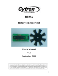
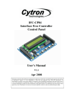
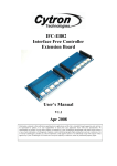
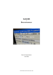
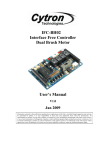
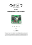
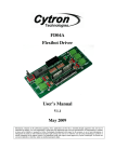
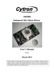
SK18A
18 Pins PIC START-UP KIT
User’s Manual
V1.1
Dec 2007
Information contained in this publication regarding device applications and the like is intended through suggestion only and
may be superseded by updates. It is your responsibility to ensure that your application meets with your specifications. No
representation or warranty is given and no liability is assumed by Cytron Technologies Incorporated with respect to the
accuracy or use of such information, or infringement of patents or other intellectual property rights arising from such use or
otherwise. Use of Cytron Technologies’s products as critical components in life support systems is not authorized except
with express written approval by Cytron Technologies. No licenses are conveyed, implicitly or otherwise, under any
intellectual property rights.
ROBOT . HEAD to TOE
Product User’s Manual – SK18A
Index
1. Introduction and Overview
2
2. Packing List
3
3. Board Layout
4
4. Product Specification
6
5. Installation (hardware)
7
5.1 Loading Program Using UIC00A Programmer
7
6. Getting Started
8
7. Warranty
9
Appendix A (schematic)
10
Created by Cytron Technologies Sdn. Bhd. – All Rights Reserved
1
ROBOT . HEAD to TOE
Product User’s Manual – SK18A
1. INTRODUCTION AND OVERVIEW
SK18A is designed to offer an easy to start board for PIC MCU user. However, all interface
and program should be developed by user. This board comes with basic element for user to
begin project development. It offers plug and use features. This kit is designed to offer:
•
•
•
•
•
•
•
•
•
•
•
•
•
Nice outlook
Industrial grade PCB
Every board is being tested before shipped to customer
Compact, powerful, flexible and robust start-up platform
Suitable for hobbyists and experts
Save development and soldering time
No extra components required for the PIC to function
11 I/O pins are nicely labeled to avoid miss-connection by users
Connector for UIC00A (low cost USB ICSP PIC Programmer) offer simple and fast
method to load program
No more frustrated work plugging PIC out and back for re-programming
Perfectly fit for 18 pins PIC16F MCU
With UIC00A, program can be loaded in less than 4 seconds
Dimension: 13.3cm x 6.9cm
SK18A come with:
•
•
•
•
•
•
•
•
•
5V voltage regulator (1A max)
20MHz oscillator
Reset button
1 x programmable push button
2 x programmable LED
Box header for UIC00A
On/Off switch for main power
DC adaptor socket as power input
And all the necessities to eliminate users difficulty in using PIC
Users are able to utilize the function of PIC by directly plugging in the I/O connectors in
whatever way that is convenient to user. With UIC00A connector on board, user can start
developing projects and have fun with this kit right away. This kit comes WITHOUT PIC
microcontroller to give the freedom for user to choose PIC type.
This document explains the method to use SK18A.
Created by Cytron Technologies Sdn. Bhd. – All Rights Reserved
2
ROBOT . HEAD to TOE
Product User’s Manual – SK18A
2. PACKING LIST
Please check the parts and components according to the packing list. If there are any parts
missing, please contact us at [email protected] immediately.
1.
2.
3.
4.
1 x SK18A board with all components shown soldered
PIC MCU – Not included, please purchase separately from Cytron website
UIC00A – Not included, please purchase separately from Cytron website
User Manual – Not included, please download from Cytron website
Created by Cytron Technologies Sdn. Bhd. – All Rights Reserved
3
ROBOT . HEAD to TOE
Product User’s Manual – SK18A
3. BOARD LAYOUT
A
B
C
D
G
H
E
F
Pin 1
of PIC
I
K
J
Label
Function
DC
power
adaptor
socket
A
Battery connector
B
Box Header for UIC00A
C
Programmer
Output LEDs from PIC MCU
D
Slide switch for main power supply
E
5V regulator
F
Label
Function
18
pin
IC
socket
for PIC MCU
G
Header pin and turn pin
H
Power indicator LED
I
J
K
Reset button
development area
A – is a DC power adaptor socket for user to plug in DC adaptor. The input voltage should be
ranged from 7 to 15V.
B – is a 2510 2 way connector for battery input. The battery voltage should be between 7 to
15V. Please ensure the polarity of voltage is correctly plugged before power up SK18A. The
“+” and “-” is have been labeled at the side of connector.
C – is a 2x5 box header for UIC00A, USB ICSP PIC Programmer.
D – consist of 2 LEDs (connected to RB6 and RB7) as active High output for PIC MCU.
These LEDs are controllable from PIC MCU.
E – is a slide switch to On/Off the power supply from DC adaptor or Battery connector.
Pushing the switch down will ON SK18A.
F – is a 5V voltage regulator 1A maximum.
G – 18 pin IC socket for user to plug in any 18 pin PIC16F MCU (8 bit). Of course the IC
package should be PDIP. Please ensure the first pin is at the top side.
Created by Cytron Technologies Sdn. Bhd. – All Rights Reserved
4
ROBOT . HEAD to TOE
Product User’s Manual – SK18A
H – Consist of 14 lines of header pin and turn pin. It is fully compatible between SK18A.
Turn pin offer simple way to check voltage with multi-meter probe. 14 pins of PIC MCU are
extended out to these pin except OSC (connected to crystal), RB6 and RB7 (connected to
LEDs and UIC00A box Header).
I – is on board 5V indicator LED. It will light ON as long as the input power is correctly
connected and the slide switch is ON.
J – is a push button with the function of Reset for PIC MCU.
K – is a development area for user to solder electronic components as input or output for PIC
MCU.
Created by Cytron Technologies Sdn. Bhd. – All Rights Reserved
5
ROBOT . HEAD to TOE
Product User’s Manual – SK18A
4. PRODUCT SPECIFICATION
SK18A is designed to offer starting up platform for development, the specification of PIC
MCU used should be referred.
Absolute Maximum Rating
Symbol
Parameter
VCC
Operating voltage
Battery or DC adaptor can be used.
Min
7
Max
15
Unit
V
Note: Only 1 power supply should be provided to SK18A.
Created by Cytron Technologies Sdn. Bhd. – All Rights Reserved
6
ROBOT . HEAD to TOE
Product User’s Manual – SK18A
5. INSTALLATION (HARDWARE)
SK18A come with UIC00A - ICSP USB programmer connector to offer simple way for
downloading program. From user feedback and experience, using UIC00A ICSP programmer
is very easy and save plenty of development time.
5.1 Loading Program Using UIC00A Programmer
Connect SK18A as shown in following figure.
From
UIC00A
Pin 1 of
PIC
SK18A should be powered either from battery or DC adaptor. Plug 18 pins PIC16F
microcontroller, please ensure the first pin of microcontroller is plugged correctly. Power up
SK18A by turning the slide switch to “ON”. Now, the hex code is ready to be loaded to
SK18A. For the usage of UIC00A, please refer to UIC00A User’s Manual.
RB7 and RB6 have been connected to UIC00A connector; both these pins are used for ICSP.
User is advice not to use these pin as input. Even when using as output, RB7 or RB6 pin are
recommended to be used in controlling non critical device such as LED, LCD, 7 segments or
buzzer. It is recommended to isolated ICSP signals from application circuit by using series
resistor (range 220 ohm and above). Please refer to UIC00A User’s Manual for further
details. Hence, in SK18A, RB7 and RB6 were designed as active High LED output.
Created by Cytron Technologies Sdn. Bhd. – All Rights Reserved
7
ROBOT . HEAD to TOE
Product User’s Manual – SK18A
6. GETTING STARTED
SK18A is ready to be plug and use, no extra driver or software is necessary. It is a hardware
platform, for the use of UIC00A, please install the necessary driver or configure the correct
setting in window. SK18A is ready be used to start the electronics interface.
The I/O of the microcontroller can be accessed through few methods:
1. I/O port (to electronic components)
• Connect the components that are needed onto the I/O port.
• Connect the electronic device to PIC MCU I/O port through Header pin.
• Extend the I/O port to development area using jumper wire.
• User may also solder the necessary interface to PCB like ordinary donut
board.
To Turn pin
To Header pin
2. I/O port (to multi-meter)
• Put the multi-meter probe on the turn pin to check the voltage.
To multi-meter probe
Created by Cytron Technologies Sdn. Bhd. – All Rights Reserved
8
ROBOT . HEAD to TOE
Product User’s Manual – SK18A
7. WARRANTY
¾
¾
¾
¾
Product warranty is valid for 6 months.
Warranty only applies to manufacturing defect.
Damage caused by miss-use is not covered under warranty.
Warranty does not cover freight cost for both ways.
Prepared by
Cytron Technologies Sdn. Bhd.
19, Jalan Kebudayaan 1A,
Taman Universiti,
81300 Skudai,
Johor, Malaysia.
Tel:
Fax:
+607-521 3178
+607-521 1861
URL: www.cytron.com.my
Email: [email protected]
[email protected]
Created by Cytron Technologies Sdn. Bhd. – All Rights Reserved
9
ROBOT . HEAD to TOE
Product User’s Manual – SK18A
Appendix A
Created by Cytron Technologies Sdn. Bhd. – All Rights Reserved
10