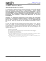
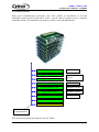
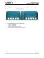
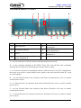
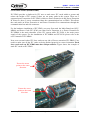
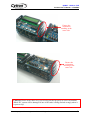
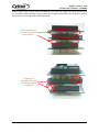
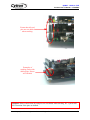
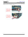
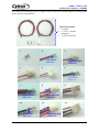
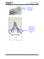
1
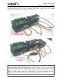
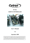
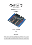
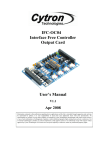
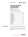
IFC-EB02
Interface Free Controller
Extension Board
User’s Manual
V1.1
Apr 2008
Information contained in this publication regarding device applications and the like is intended through suggestion only and may
be superseded by updates. It is your responsibility to ensure that your application meets with your specifications. No
representation or warranty is given and no liability is assumed by Cytron Technologies Incorporated with respect to the accuracy
or use of such information, or infringement of patents or other intellectual property rights arising from such use or otherwise. Use
of Cytron Technologies’s products as critical components in life support systems is not authorized except with express written
approval by Cytron Technologies. No licenses are conveyed, implicitly or otherwise, under any intellectual property rights.
ROBOT . HEAD to TOE
Product User’s Manual – IFC-EB02
Index
1. Introduction and Overview
1
1.0 Introduction of Interface Free Controller
1
1.1 System Overview
2
2. Packaging List
3
3. Product Specification
4
3.1 Input and Output device
4
3.2 Operating Voltage
4
4. Board or Product Layout
5
5. Installation (hardware)
6
6. Warranty (6 months)
16
Created by Cytron Technologies Sdn. Bhd. – All Rights Reserved
ROBOT . HEAD to TOE
Product User’s Manual – IFC-EB02
1. INTRODUCTION AND OVERVIEW
1.0 Introduction of Interface Free Controller
IFC (Interface Free Controller) offer a new concept of developing microcontroller embedded
system and also robotics system. With IFC, no more frustration in determine hardware
interface and configuring peripheral in software. Checking few hundreds pages of data sheet
can be waved. With the concept of interfacing card, user may stack as many as 64 cards in a
system to get infinite combination of peripherals. The design aim is to offer 3 simple steps in
microcontroller system development – Configure card’s address, Stack IFC cards, Write
Program and Run!
Furthermore, with functions based software library, user save valuable time during software
development by concentrating on algorithm development. No more flipping or scrolling PIC
data sheet looking for ADCON0, T1CON or even TRISA. With just a programming hand
book, user may simply copy the header file, call comprehensive functions and it’s ready to
rock.
IFC come with a brain card (main controller) where the main program is loaded. There are
several cards available for robotics development such as control panel, 15A brush motor
driver, brushless motor controller, counter and digital input, output card and power card. This
document will focus on the Extension board, IFC-EB02. This card has been designed with
capabilities and features of:
• Industrial grade PCB.
• Every component is soldered properly and tested before board is shipped.
• 2 x External Power In terminal.
• 8 x External Power Out terminal.
• Provide a platform for IFC user to stack more IFC cards within a system and reduce
the height of IFC system if there are too many cards in the system.
• Provide 2 power extension (Power Extension A and Power Extension B) for user to
supply external power source to IFC slave card.
Created by Cytron Technologies Sdn. Bhd. – All Rights Reserved
1
ROBOT . HEAD to TOE
Product User’s Manual – IFC-EB02
1.1 System Overview
With serial communication perception, IFC offer million of possibilities to develop
embedded system creatively and easily. In IFC, several cards are stacked to get a complete
embedded system. The minimum card requires is Power card and Main Board.
More cards
Control Panel Card
Digital Input Card
Output Card
More devices
Encoder, digital
sensor
Relays, etc
Brushless Motor Card
Brushless motors
Brush Motor Card
Brushless motors
Main Brain
Brush motor
Power card
Extension Board
Power and
communication
This document explains the method to use IFC-EB02.
Created by Cytron Technologies Sdn. Bhd. – All Rights Reserved
2
ROBOT . HEAD to TOE
Product User’s Manual – IFC-EB02
2. PACKAGING LIST
Please check the parts and components according to the packing list. If there are any parts
missing, please contact us at [email protected] immediately.
1. 1 x IFC Brushless Motor Card ,IFC-EB0202 with:
• 8 x power out terminal.
• 2 x power in terminal.
• Female connector for every terminal.
• Other electronics components soldered on board.
Created by Cytron Technologies Sdn. Bhd. – All Rights Reserved
3
ROBOT . HEAD to TOE
Product User’s Manual – IFC-EB02
3. PRODUCT SPECIFICATION
3.1 Input and Output device
The output devices on EB02 are as below:
• 8 Power Out terminal which allow user to provide 12V or 24V power source to
other IFC slave cards, for example, Brush Motor card (IFC-MD15A), Brushless
Motor card (IFC-BL02) and Output card (IFC-OC04).
The input devices on EB02 are as below:
• 2 Power In terminal which need to connect to 12V or 24V power supply.
3.2 Operating Voltage
The operation voltage of IFC-EB02 is 12V. User needs to connect 12V or 24V power supply
to the Power In terminal of EB02, it is depends on the application. The 12V or 24V power
supply can come from Power card (IFC-PC00) or external battery. Please refer hardware
setup in chapter 5.0 Installation (hardware) for connecting power to Extension Board.
Created by Cytron Technologies Sdn. Bhd. – All Rights Reserved
4
ROBOT . HEAD to TOE
Product User’s Manual – IFC-EB02
4. BOARD OR PRODUCT LAYOUT
A
B
C
A
B
A
A
F
Label
G
F
Function
D
Label
A
Side connector
E
B
Orientation marking
F
C
Arrow
G
D
External Power Out terminal for
Power Extension B
E
D
Function
External Power In terminal for Power
Extension B
External Power Out terminal for
Power Extension A
External Power In terminal for Power
Extension A
A – are side connector for stack card and communication between cards.
B – is the orientation marking on IFC-EB02. Every IFC card will have this orientation
marking, this is to help user in ensuring the cards are stack correctly.
C – is a arrow to help user in ensuring the cards are stack correctly. Every IFC card will have
this arrow; user needs to ensure that the arrow points to the same direction when IFC cards
are stack together.
D – are four External Power Out connector from Power Extension B for user to connect
external power source.
E– is a External Power In connector from Power Extension B for user to connect external
power source.
F – are four External Power Out connector from Power Extension A for user to connect
external power source.
G – is a External Power In connector from Power Extension A for user to connect external
power source.
Created by Cytron Technologies Sdn. Bhd. – All Rights Reserved
5
ROBOT . HEAD to TOE
Product User’s Manual – IFC-EB02
5. INSTALLATION (HARDWARE)
IFC-EB02 provides a platform for IFC user to stack more IFC cards within a system and
reduce the height of IFC system if there are too many cards in the system. There are 2
separated power extension on IFC-EB02, which are Power Extension A and Power Extension
B. However, these 2 power extensions share the communication bus on EB02. This allows
the cards stack on Power Extension A and Power Extension B to communicate through the
communication bus and side connector.
For the hardware installation of IFC-EB02, user may first stack the Main Board card (IFCMB00) and Power Card (IFC-PC00) on either Power Extension A or Power Extension B.
IFC-MB00 is the main controller of the IFC system while IFC-PC00 is the main power
supply of the system. For the installation of IFC-MB00 and IFC-PC00 please refer to the
user’s manual of IFC-MB00.
Next, user can stack other IFC slave cards on any side of Power extension (IFC-EB02). User
needs to make sure all the IFC cards are being stacked properly in correct orientation. Each
slave card stack on IFC-EB02 must have unique address. Figure shows the example of
stack IFC cards on IFC-EB02.
Ensure the arrow
points to the same
direction
Ensure the arrow
points to the same
direction
Created by Cytron Technologies Sdn. Bhd. – All Rights Reserved
6
ROBOT . HEAD to TOE
Product User’s Manual – IFC-EB02
Ensure the
orientation
marking at the
same side.
Ensure the
orientation
marking at the
same side.
Cautions: Please ensure that every card is being stacked properly in correct orientation.
Whole IFC system will be damaged if one of the cards is being stacked wrongly when it
is powered up.
Created by Cytron Technologies Sdn. Bhd. – All Rights Reserved
7
ROBOT . HEAD to TOE
Product User’s Manual – IFC-EB02
Besides stack every card in correct orientation, user must also require to ensure all card pins
are not shifted when stacking. Figures show the example of stacking cards in proper location
and example of stacking cards with shifted pins.
Ensure that all card
pins are not shifted
when stacking.
Examples of
stacking cards with
shifted pins. Please
AVOID this!
Created by Cytron Technologies Sdn. Bhd. – All Rights Reserved
8
ROBOT . HEAD to TOE
Product User’s Manual – IFC-EB02
Ensure that all card
pins are not shifted
when stacking.
Examples of
stacking cards with
shifted pins. Please
AVOID this!
Cautions: Please ensure that all card pins are not shifted when stacking. IFC system will
NOT function if the pins are shifted.
Created by Cytron Technologies Sdn. Bhd. – All Rights Reserved
9
ROBOT . HEAD to TOE
Product User’s Manual – IFC-EB02
After that, connect the battery to Power Card, IFC-PC00. IFC-PC00 is the main power
supply. User need to connect IFC-PC00 with 12V battery to supply power to all IFC card. If
brushless motor used, 2 x 12V batteries is needed.
Connect 1 x 12V
battery to supply
operating voltage to
IFC. Ensure the
polarity is correct.
If 24V is needed in
the system, connect
2 x 12V batteries to
PC00. Ensure the
polarity is correct.
Created by Cytron Technologies Sdn. Bhd. – All Rights Reserved
10
ROBOT . HEAD to TOE
Product User’s Manual – IFC-EB02
For power supply to EB02 card, user can connect external power source from IFC Power
Card (IFC-PC00) to External Power In on Extension Board (IFC-EB02) or connect external
battery to External Power In on Extension board (IFC-EB02). Figure below show the
connection of External Power from Power card and external battery. User needs to make
sure the polarity is correct when connect external power source for extension board
(EB02).
External power
source from IFC
Power Card.
External
power source
from 2 x 12V
batteries.
Created by Cytron Technologies Sdn. Bhd. – All Rights Reserved
11
ROBOT . HEAD to TOE
Product User’s Manual – IFC-EB02
User may follow the steps below to build a cable connector for connecting the external power
source from 2 extra batteries.
Materials needed:
a. 4 x cable
b. 1 x 3961-3 female
connector
c. 3 x 3961 iron pins
2
1
3
Solder some
lead on it.
5
4
Insert into 3961
connector.
6
Solder some
lead on it.
7
8
9
Insert into 3961
connector.
Solder another
cable on it.
11
10
Solder some
lead on it.
12
Insert into 3961
connector.
Created by Cytron Technologies Sdn. Bhd. – All Rights Reserved
12
ROBOT . HEAD to TOE
Product User’s Manual – IFC-EB02
Ensure the iron
pins are fully
inserted to the
connector
Connect the cable
to batteries. Please
ensure the
polarity is correct.
Red for positive
(+) while black for
negative (-).
-
+
12V
Battery
-
+
12V
Battery
Created by Cytron Technologies Sdn. Bhd. – All Rights Reserved
13
ROBOT . HEAD to TOE
Product User’s Manual – IFC-EB02
User may supply external power source to IFC slave card by connect the External Power Out
Terminal from any side of Power extension (IFC-EB02). Figure show the example
connection from External Power Out to IFC slave card.
External power source
from IFC-PC00
External power
source from 2 x 12V
batteries.
Note: The voltage connected to Power In Terminal on Power extension is equal to the
voltage supply to Power Out Terminal. For example, supply 12V to Power In Terminal
on Power Extension A, the output voltage from 4 x Power Out Terminal on Power
Extension A are equal to 12V. When connect external power source for IFC slave cards
from IFC-EB02, please ensure the voltage supply to Power In Terminal on Power
Extension is compatible with the require external power source of the slave card.
Created by Cytron Technologies Sdn. Bhd. – All Rights Reserved
14
ROBOT . HEAD to TOE
Product User’s Manual – IFC-EB02
To open the cards, user can use the IFC card’s opener to open the stacked cards. Figure
shows the method to open cards with the opener.
1
2
3
Caution: Please use the opener to open IFC cards to avoid damage of the pins or cards.
Created by Cytron Technologies Sdn. Bhd. – All Rights Reserved
15
ROBOT . HEAD to TOE
Product User’s Manual – IFC-EB02
7. WARRANTY
¾
¾
¾
¾
Product warranty is valid for 6 months.
Warranty only applies to manufacturing defect.
Damage caused by miss-use is not covered under warranty.
Warranty does not cover freight cost for both ways.
Prepared by
Cytron Technologies Sdn. Bhd.
19, Jalan Kebudayaan 1A,
Taman Universiti,
81300 Skudai,
Johor, Malaysia.
Tel:
Fax:
+607-521 3178
+607-521 1861
URL: www.cytron.com.my
Email: [email protected]
[email protected]
Created by Cytron Technologies Sdn. Bhd. – All Rights Reserved
16