1
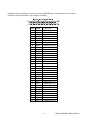
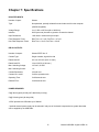
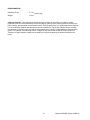
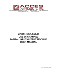
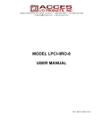
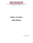
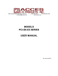
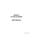
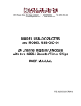
ISOLATED DIGITAL
INPUT / RELAY OUTPUT
BOARD
MODEL USB-IIRO-16
USB-IIRO-8
USB-RO-16
USB-II-16
USER MANUAL
File: MUSB-IIRO-16.B1g
Notice
The information in this document is provided for reference only. Portwell does not assume any liability arising
out of the application or use of the information or products described herein. This document may contain or
reference information and products protected by copyrights or patents and does not convey any license
under the patent rights of Portwell, nor the rights of others.
IBM PC, PC/XT, and PC/AT are registered trademarks of the International Business Machines Corporation.
Printed in USA. Copyright 2005 by Portwell I/O Products, Inc. All rights reserved.
WARNING!!
ALWAYS CONNECT AND DISCONNECT YOUR FIELD CABLING WITH
THE COMPUTER POWER OFF. ALWAYS TURN COMPUTER POWER OFF
BEFORE INSTALLING A BOARD. CONNECTING AND DISCONNECTING
CABLES, OR INSTALLING BOARDS INTO A SYSTEM WITH THE
COMPUTER OR FIELD POWER ON MAY CAUSE DAMAGE TO THE I/O
BOARD AND WILL VOID ALL WARRANTIES, IMPLIED OR EXPRESSED.
2
Manual USB-IIRO-16(8)/II-16/RO-16
Warranty
Prior to shipment, Portwell equipment is thoroughly inspected and tested to applicable specifications.
However, should equipment failure occur, Portwell assures its customers that prompt service and support will
be available. All equipment originally manufactured by Portwell which is found to be defective will be repaired
or replaced subject to the following considerations.
Terms and Conditions
If a unit is suspected of failure, contact Portwell' Customer Service department. Be prepared to give the unit
model number, serial number, and a description of the failure symptom(s). We may suggest some simple
tests to confirm the failure. We will assign a Return Material Authorization (RMA) number which must appear
on the outer label of the return package. All units/components should be properly packed for handling and
returned with freight prepaid to the Portwell designated Service Center, and will be returned to the
customer's/user's site freight prepaid and invoiced.
Coverage
First Three Years: Returned unit/part will be repaired and/or replaced at Portwell option with no charge for
labor or parts not excluded by warranty. Warranty commences with equipment shipment.
Following Years: Throughout your equipment's lifetime, Portwell stands ready to provide on-site or in-plant
service at reasonable rates similar to those of other manufacturers in the industry.
Equipment Not Manufactured by Portwell
Equipment provided but not manufactured by Portwell is warranted and will be repaired according to the
terms and conditions of the respective equipment manufacturer's warranty.
General
Under this Warranty, liability of Portwell is limited to replacing, repairing or issuing credit (at Portwell
discretion) for any products which are proved to be defective during the warranty period. In no case is Portwell
liable for consequential or special damage arriving from use or misuse of our product. The customer
is responsible for all charges caused by modifications or additions to Portwell equipment not approved in
writing by Portwell or, if in Portwell opinion the equipment has been subjected to abnormal use. "Abnormal
use" for purposes of this warranty is defined as any use to which the equipment is exposed other than that
use specified or intended as evidenced by purchase or sales representation. Other than the above, no other
warranty, expressed or implied, shall apply to any and all such equipment furnished or sold by Portwell.
3
Manual USB-IIRO-16(8)/II-16/RO-16
TABLE OF CONTENTS
Chapter 1: Introduction..................................................................................................................................... 5
Figure 1-1: Block Diagram........................................................................................................................... 7
Figure 1-2: Example of one Input Circuit..................................................................................................... 7
Chapter 2: Installation....................................................................................................................................... 8
Chapter 3: Option Selection ............................................................................................................................. 9
Figure 3-1: Option Selection Map.............................................................................................................. 10
Chapter 4: USB Address Information ............................................................................................................ 11
Chapter 5: Programming ................................................................................................................................ 12
Chapter 6: Connector Pin Assignments ....................................................................................................... 13
Chapter 7: Specifications ...............................................................................................................................15
4
Manual USB-IIRO-16(8)/II-16/RO-16
Chapter 1: Introduction
This board is an ideal solution for adding portable, easy-to-install digital I/O to any computer with a USB port.
As a USB 2.0 high speed device it offers the fastest speed available with the USB bus, while being
compatible with both USB 1.1 and USB 2.0 ports. The board is plug-and-play allowing for quick
connect/disconnect whenever you need additional I/O on your computer.
Model Options
16 isolated digital inputs and 16 relay outputs, enclosure, module and screw terminal board
16 isolated digital inputs only version
16 relay outputs only version
8 isolated digital inputs and 8 relay outputs version
Accessories:
Internal plug in screw termination board (Green screw terminals = AWG 26-16)
(Gray screw terminals = AWG 28-20)
External power supply AC/DC adapter
Options:
-OEM
-E
-DIN
Board Only version (no enclosure or screw terminal board)
Economy model (no screw terminal board)
DIN rail mounting provision
5
Manual USB-IIRO-16(8)/II-16/RO-16
Functional Description
FEATURES:
•
High-Speed USB 2.0 device, USB 1.1 compatible
•
16 optically isolated inputs
•
16 Form C electromechanical 1A relays
•
Internal, removable screw terminal board for easy wiring
•
Small (4" x 4"x 1.25") rugged industrial enclosure
•
Custom high-speed function driver
•
PC/104 module size and mounting compatibility
INPUTS
The board provides sixteen optically-isolated inputs. These inputs can accept either AC or DC signals and
are not polarity sensitive. Input signals are rectified by photocoupler diodes while unused power gets
dissipated through a 1.8k-ohm resistor in series. The inputs may be driven by either DC sources of 3 to 31
volts (rms) or AC sources at frequencies of 40 Hz to 10 KHz. Standard 12/24 AC control transformer outputs
can be accepted as well. External resistors connected in series may be used to extend the input voltage
range, however this will raise the input threshold range. Consult with factory for available modified input
ranges.
Each input circuit contains a switchable filter that has a 4.7 millisecond time constant. (Without filtering, the
response is less then 40 microseconds) The filter must be selected for AC inputs in order to eliminate the
on/off response to AC. The filter is also valuable for use with slow DC input signals in a noisy environment.
The filter may be switched out for DC inputs in order to obtain faster response. Filters are individually
selected by jumpers. The filters are switched into the circuit when the jumpers are installed in position FLT0
to FLT15.
OUTPUTS
The board’s outputs are comprised of sixteen FORM C SPDT electro mechanical relays. These relays are all
de-energized at power-on.
SCREW TERMINAL ACCESSORY BOARD
A Screw Terminal Accessory board is included with the unit, except for the Economy (E) and OEM versions.
The board provides access to all 80 I/O signals via removable screw terminals. Each removable screw
terminal carries 8 I/O signals, signal names are clearly marked on the accessory board's silk screen. The
screw terminal board plugs directly onto the I/O board while fitting inside the rugged industrial enclosure.
USB CONNECTOR
The USB connector is a Type B connector and mates with the cable provided. The USB port provides
communication signals along with +5 VDC power. The board can be powered from the USB port or, if
needed for higher current applications, an external power supply can be used.
6
Manual USB-IIRO-16(8)/II-16/RO-16
LED
The LED on the front of the enclosure is used to indicate power and data transmissions. When the LED is in
an illuminated steady green state, this signifies that the board is successfully connected to the computer and
has been detected and configured by the operating system. When the LED flashes continuously, this
signifies that there is data being transmitted over the USB bus.
USB 1.1 / 2.0
16
OPTO
ISOLATORS
SCHMITT
TRIGGER
BUFFER
INTERFACE
BUFFERS
W ITH
MICROCONTROLLER
16 SPDT
RELAY
OUTPUTS
50-PIN OUTPUT CONNECTOR
34-PIN INPUT CONNECTOR
JUMPER
SELECTED
FILTERS
USB
CONNECTOR
Figure 1-1: Block Diagram
1.8K
Vcc
AC or
DC
INPUT
47K
.1uF
4.7K
FILTER JU MPER
Figure 1-2: Example of one Input Circuit
7
Manual USB-IIRO-16(8)/II-16/RO-16
Chapter 2: Installation
Software CD Installation
These paragraphs are intended to detail the software installation steps as well as describe what is
being installed.
The software provided with this board is contained on one CD and must be installed onto your
hard disk prior to use. To do this, perform the following steps as appropriate for your operating
system. Substitute the appropriate drive letter for your drive where you see d: in the examples
below.
WIN98/Me/2000/XP/2003
a.
b.
c.
Place the CD into your CD-ROM drive.
The CD should automatically run the install program. If the install program does not run,
click START | RUN and type BGLQR?JJ, click OK or press -.
Follow the on-screen prompts to install the software for this board.
Hardware Installation
The board can be installed in any USB 2.0 or USB 1.1 port. Please refer to the USB I/O Quick Start
Guide which can be found on the CD, for specific, quick steps to complete the hardware and
software installation.
8
Manual USB-IIRO-16(8)/II-16/RO-16
Chapter 3: Option Selection
Refer to the setup programs on the CD provided with the board. Also, refer to the Block Diagram and the
Option Selection Map when reading this section of the manual.
Input Power
This is an option for applications that use more current than what your computer can provide on the USB
port (typically 500 mA). The DC jack has a 2.00mm post on board and is designed to be used with the 9
VDC AC/DC external power supply that ships with this option. The voltage regulator on board regulates the 9
VDC and provides 5 VDC to the onboard circuitry. When using external power, switch the jumper located
near the USB connector to VEXT, otherwise when the jumper is in the VUSB position current is drawn from
the USB port.
Filter Response Switch
Jumpers are used to select input filtering on a channel-by-channel basis. When jumper FLT0 is installed,
additional filtering is introduced for input bit 0, FLT1 for bit 1, etc.
JUMPER SELECTION
Bit Filtered
JUMPER SELECTION
Bit Filtered
FLT-0
FLT-1
FLT-2
FLT-3
FLT-4
FLT-5
FLT-6
FLT-7
IN00
IN01
IN02
IN03
IN04
IN05
IN06
IN07
FLT-8
FLT-9
FLT-10
FLT-11
FLT-12
FLT-13
FLT-14
FLT-15
IN08
IN09
IN10
IN11
IN12
IN13
IN14
IN15
This additional filtering provides a slower response for DC signals as described previously and must be used
when AC inputs are applied.
9
Manual USB-IIRO-16(8)/II-16/RO-16
Pin 1
0.29"
0.44"
0.29"
0.29"
5.21"
P2
VEXT
NO
FILTER
FILTER
VEXT VUSB
0.29"
USE DC
POWER
P3
Pin 1
0.51"
VUSB
POWER FROM USB
0
15
USB
0.29"
0.29"
3.775”
Figure 3-1: Option Selection Map
10
Manual USB-IIRO-16(8)/II-16/RO-16
Chapter 4: USB Address Information
Use the provided driver to access the USB board. This driver will allow you to determine how many
supported USB devices are currently installed, and each device’s type. This information is returned as a
Vendor ID (VID), Product ID (PID) and Device Index.
The board’s VID is “0x1605", and its PID is “0x8010".
The Device Index is determined by how many of the device you have in your system, and provides a unique
identifier allowing you to access a specific board at will.
11
Manual USB-IIRO-16(8)/II-16/RO-16
Chapter 5: Programming
The driver software provided with the board uses a 32-bit .dll front end compatible with any Windows
programming language. Samples provided in Borland C++Builder, Borland Delphi, Microsoft Visual Basic,
and Microsoft Visual C++ demonstrate the use of the driver.
The following functions are provided by the driver in Windows.
These functions will allow you to read or write individual bits, bytes, or the entire board worth of data. In
addition, counter-timer functionality and board-level functions complete the driver package.
For detailed information on each function refer to the .html Driver Manual located in the Win32 directory for
this board.
unsigned long GetDevices(void )
unsigned long QueryDeviceInfo(DeviceIndex, pPID, pName, pDIOBytes, pCounters)
unsigned long DIO_Configure(DeviceIndex, bTristate, pOutMask, pData)
unsigned long DIO_Write1(DeviceIndex, BitIndex, bData)
unsigned long DIO_Write8(DeviceIndex, ByteIndex, Data)
unsigned long DIO_WriteAll(DeviceIndex,pData)
unsigned long DIO_Read8(DeviceIndex, ByteIndex,pBuffer)
unsigned long DIO_ReadAll(DeviceIndex,Buffer)
unsigned long CTR_8254Mode(DeviceIndex, BlockIndex, CounterIndex, Mode)
unsigned long CTR_8254ModeLoad(DeviceIndex, BlockIndex, CounterIndex,Mode, LoadValue)
unsigned long CTR_8254ReadModeLoad(DeviceIndex, BlockIndex, CounterIndex, Mode, LoadValue,
pReadValue)
unsigned long CTR_8254Read(DeviceIndex, BlockIndex, CounterIndex, pReadValue)
unsigned long CTR_StartOutputFreq(DeviceIndex, CounterIndex, pHz)
12
Manual USB-IIRO-16(8)/II-16/RO-16
Chapter 6: Connector Pin Assignments
Relay outputs are connected to the board via a 50-pin HEADER type connector named P3. The mating
connector is an IDC type with 0.1 inch centers or equivalent. The wiring may be directly from the signal
sources or may be on ribbon cable from screw terminal accessory boards such as the STA-50. Pin
assignments follow.
PIN
1
2
3
4
5
6
7
8
9
10
11
12
13
14
15
16
17
18
19
20
21
22
23
24
25
26
27
28
29
30
31
32
33
34
35
36
37
38
39
40
41
42
43
44
45
46
47
48
49
50
NAME
OUT15-NO
OUT15-C
OUT15-NC
OUT14-NO
OUT14-C
OUT14-NC
OUT13-NO
OUT13-C
OUT13-NC
OUT12-NO
OUT12-C
OUT12-NC
OUT11-NO
OUT11-C
OUT11-NC
OUT10-NO
OUT10-C
OUT10-NC
OUT09-NO
OUT09-C
OUT09-NC
OUT08-NO
OUT08-C
OUT08-NC
FUNCTION
Relay 15, Normally-Open Contact
Relay 15, Common Contact
Relay 15, Normally-Closed Contact
Relay 14, Normally-Open Contact
Relay 14, Common Contact
Relay 14, Normally-Closed Contact
Relay 13, Normally-Open Contact
Relay 13, Common Contact
Relay 13, Normally-Closed Contact
Relay 12, Normally-Open Contact
Relay 12, Common Contact
Relay 12, Normally-Closed Contact
Relay 11, Normally-Open Contact
Relay 11, Common Contact
Relay 11, Normally-Closed Contact
Relay 10, Normally-Open Contact
Relay 10, Common Contact
Relay 10, Normally-Closed Contact
Relay 09, Normally-Open Contact
Relay 09, Common Contact
Relay 09, Normally-Closed Contact
Relay 08, Normally-Open Contact
Relay 08, Common Contact
Relay 08, Normally-Closed Contact
OUT07-NC
OUT07-C
OUT07-NO
OUT06-NC
OUT06-C
OUT06-NO
OUT05-NC
OUT05-C
OUT05-NO
OUT04-NC
OUT04-C
OUT04-NO
OUT03-NC
OUT03-C
OUT03-NO
OUT02-NC
OUT02-C
OUT02-NO
OUT01-NC
OUT01-C
OUT01-NO
OUT00-NC
OUT00-C
OUT00-NO
Relay 07, Normally-Closed Contact
Relay 07, Common Contact
Relay 07, Normally-Open Contact
Relay 06, Normally-Closed Contact
Relay 06, Common Contact
Relay 06, Normally-Open Contact
Relay 05, Normally-Closed Contact
Relay 05, Common Contact
Relay 05, Normally-Open Contact
Relay 04, Normally-Closed Contact
Relay 04, Common Contact
Relay 04, Normally-Open Contact
Relay 03, Normally-Closed Contact
Relay 03, Common Contact
Relay 03, Normally-Open Contact
Relay 02, Normally-Closed Contact
Relay 02, Common Contact
Relay 02, Normally-Open Contact
Relay 01, Normally-Closed Contact
Relay 01, Common Contact
Relay 01, Normally-Open Contact
Relay 00, Normally-Closed Contact
Relay 00, Common Contact
Relay 00, Normally-Open Contact
13
Manual USB-IIRO-16(8)/II-16/RO-16
Isolated Inputs are connected to the board via a 34-pin HEADER type connector named P2. The mating
connector is an IDC type with 0.1 inch centers or equivalent.
PIN
1
2
3
4
5
6
7
8
9
10
11
12
13
14
15
16
17
18
19
20
21
22
23
24
25
26
27
28
29
30
31
32
33
34
NAME
IN00 A
IN00 B
IN01 A
IN01 B
IN02 A
IN02 B
IN03 A
IN03 B
IN04 A
IN04 B
IN05 A
IN05 B
IN06 A
IN06 B
IN07 A
IN07 B
FUNCTION
Isolated Input 00 A
Isolated Input 00 B
Isolated Input 01 A
Isolated Input 01 B
Isolated Input 02 A
Isolated Input 02 B
Isolated Input 03 A
Isolated Input 03 B
Isolated Input 04 A
Isolated Input 04 B
Isolated Input 05 A
Isolated Input 05 B
Isolated Input 06 A
Isolated Input 06 B
Isolated Input 07 A
Isolated Input 07 B
IN08 A
IN08 B
IN09 A
IN09 B
IN10 A
IN10 B
IN11 A
IN11 B
IN12 A
IN12 B
IN13 A
IN13 B
IN14 A
IN14 B
IN15 A
IN15 B
Isolated Input 08 A
Isolated Input 08 B
Isolated Input 09 A
Isolated Input 09 B
Isolated Input 10 A
Isolated Input 10 B
Isolated Input 11 A
Isolated Input 11 B
Isolated Input 12 A
Isolated Input 12 B
Isolated Input 13 A
Isolated Input 13 B
Isolated Input 14 A
Isolated Input 14 B
Isolated Input 15 A
Isolated Input 15 B
14
Manual USB-IIRO-16(8)/II-16/RO-16
Chapter 7: Specifications
ISOLATED INPUTS
Number of inputs:
Sixteen
Type:
Non-polarized, optically isolated from each other and from the computer
(CMOS compatible)
Voltage Range:
3 to 31 DC or AC Rms (40 to 10000 Hz)
Isolation:
500V*(see note) channel-to-ground or channel-to channel
Input Resistance:
1.8K ohms in series with opto coupler
Filter Response Times:
Rise Time = 4.7 mS / Fall Time = 4.7 mS
Non-Filter Response Times:
Rise Time = 10 uS / Fall Time = 30 uS
RELAY OUTPUTS
Number of outputs:
Sixteen SPDT form C
Contact Type:
Single crossbar; Ag with Au clad
Rated Load AC:
0.5 A at 125 VAC (62.5 VA max.)
Rated Load DC:
1A at 24 VDC (30 W max.)
Max. Switching Voltage:
125 VAC, 60 VDC
Max. Switching Current:
1A
Contact Resistance:
100 mΩ max.
Contact Life: mech'l:
5 million operations min.
Operating Time:
5 milliseconds max.
Release Time:
5 milliseconds max.
POWER REQUIRED
5V@ 30mA typical (all relays off, add 30mA per relay)
5V@ 510mA typical (all relays ON)
+5VDC provided via USB cable up to 500mA**
**optional external power supply can be ordered if relay use of the board is expected to be greater than what
can be supplied by the USB cable.
15
Manual USB-IIRO-16(8)/II-16/RO-16
ENVIRONMENTAL
Operating Temp:
0 - 70 oC (Non-icing)
Weight:
14.5 oz
*Notes on Isolation: Opto-Isolators and connectors are rated for at least 500V, but isolation voltage
breakdowns will vary and is affected by factors like cabling, spacing of pins, spacing between traces on the
PCB, humidity, dust and other environmental factors. This is a safety issue so a careful approach is required.
For CE certification, isolation was specified at 40V AC and 60V DC. The design intention was to eliminate
the influence of common mode. Use proper wiring techniques to minimize voltage between channels and to
ground. For example, when working with AC voltages do not connect the hot side of the line to an input.
Tolerance of higher isolation voltage can be obtained on request by applying a conformal coating to the
board.
16
Manual USB-IIRO-16(8)/II-16/RO-16
Customer Comments
If you experience any problems with this manual or just want to give us some feedback, please email us at:
[email protected]. Please detail any errors you find and include your mailing address so that we can
send you any manual updates.
17
Manual USB-IIRO-16(8)/II-16/RO-16