1
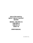
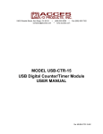
C
C
C
MODEL USB-IIRO4-2SM
USER MANUAL
FILE: MUSB-IIRO4-2SM.A1l
Notice
The inform ation in this docu me nt is pro vided for referen ce only. Portwell does not assume any liability
arising out of the application or use of the information or products described herein. This document may
contain or reference information and products protected by copyrights or patents and does not convey any
license under the patent rights of Portwell, nor the rights of others.
IBM PC, PC/XT, and PC/AT are registered trademarks of the International Business Machines
Corporation.
Printed in USA. Copyright 2006 by Portwell I/O Products Inc. All rights reserved.
WARNING!!
ALWAYS CONNECT AND DISCONNECT YOUR FIELD CABLING WITH
THE COMPUTER POWER OFF. ALWAYS TURN COMPUTER POW ER
OFF BEFORE INSTALLING A CARD. CONNECTING AND
DISCONNECTING CABLES, OR INSTALLING CARDS INTO A SYSTEM
WITH THE COMPUTER OR FIELD POWER ON MAY CAUSE DAMAGE
TO THE I/O CARD AND WILL VOID ALL WARRANTIES, IMPLIED OR
EXPRESSED.
2
Manual USB-IIRO4-2SM
Warranty
Prior to ship me nt, Portwell equipme nt is thoroug hly inspec ted and tested to applicab le spe cification s.
How ever, should eq uipm ent failure occ ur, Portwell ass ures its cus tome rs that prom pt service a nd su pport
will be available. All equipment originally manufactured by Portwell which is found to be defective will be
repaired or replaced subject to the following considerations.
Terms and Conditions
If a unit is suspected of failure, contact Portwell' Customer Service department. Be prepared to give the
unit model number, serial number, and a description of the failure symptom(s). We may suggest some
simple tests to confirm the failure. We w ill assign a Return Material Authorization (RMA) numbe r which
must appear on the outer label of the return package. All units/components should be properly packed for
handling and returned with freight prepaid to the Portwell designated Service Center, and will be returned
to the customer's/user's site freight prepaid and invoiced.
Coverage
First Three Years: Returned unit/part will be repaired and/or replaced at Portwell option with no charge for
labor or parts not excluded by w arran ty. Warran ty com me nce s with equ ipm ent shipm ent.
Following Years: Throughout your equipment's lifetime, Portwell stands ready to provide on-site or in-plant
service at reasonable rates similar to those of other manu facturers in the industry.
Equipment Not Manufactured by Portwell
Equipment provided but not manufactured by Portwell is warranted and will be repaired according to the
terms and c onditions of the respective equipme nt manu facturer's warranty.
General
Under this Warranty, liability of Portwell is limited to replacing, repairing or issuing credit (at Portwell
disc retion) for any pro ducts w hich are proved to be defective during the wa rran ty pe riod. In no cas e is
Portwell liable for consequential or special damage arriving from use or misuse of our product. The
customer is responsible for all charges caused by modifications or additions to Portwell equipment not
approved in writing by Portwell or, if in Portwell opinion the equipment has been subjected to abnormal
use. "A bnorm al us e" for purposes of th is warra nty is defined as an y use to wh ich th e equipm ent is
exp ose d other than that use specified or intend ed a s evidenced by pu rcha se or sales repre sen tation.
Other than the above, no other warranty, expressed or implied, shall apply to any and all such equipment
furnished or sold by Portwell.
3
Manual USB-IIRO4-2SM
TABLE OF CONTENTS
Chapter 1: Introduction . . . . . . . . . . . . . . . . . . . . . . . . . . . . . . . . . . . . . . . . . . . . . . . . . . . . . . . . . . . . . . 5
Comm unication Mode . . . . . . . . . . . . . . . . . . . . . . . . . . . . . . . . . . . . . . . . . . . . . . . . . . . . . . . . . . 6
Figure 1-1: Block Diagram . . . . . . . . . . . . . . . . . . . . . . . . . . . . . . . . . . . . . . . . . . . . . . . . 9
Chapter 2: Installation . . . . . . . . . . . . . . . . . . . . . . . . . . . . . . . . . . . . . . . . . . . . . . . . . . . . . . . . . . . . . . 10
Hardware Installation . . . . . . . . . . . . . . . . . . . . . . . . . . . . . . . . . . . . . . . . . . . . . . . . . . . . . . . . . . 10
Chapter 3: Option Selection . . . . . . . . . . . . . . . . . . . . . . . . . . . . . . . . . . . . . . . . . . . . . . . . . . . . . . . . . 11
Figure 3-1: Option Selection Map . . . . . . . . . . . . . . . . . . . . . . . . . . . . . . . . . . . . . . . . . . 12
Chapter 4: Address Selection . . . . . . . . . . . . . . . . . . . . . . . . . . . . . . . . . . . . . . . . . . . . . . . . . . . . . . . . 13
Chapter 5: Programming . . . . . . . . . . . . . . . . . . . . . . . . . . . . . . . . . . . . . . . . . . . . . . . . . . . . . . . . . . . . 14
Ch apter 6 : Con nector Pin Ass ignm ents . . . . . . . . . . . . . . .
Tab le 6-1: IIRO Conne ctor P in As signme nts .
Table 6-2: DB25 Pinout . . . . . . . . . . . . . . . . .
Tab le 6-3: Seria l Con nec tor Pin Ass ignm ents
4
.
.
.
.
.
.
.
.
.
.
.
.
.
.
.
.
.
.
.
.
.
.
.
.
.......
.......
.......
.......
.
.
.
.
.
.
.
.
.
.
.
.
.
.
.
.
.
.
.
.
.......
.......
.......
.......
.
.
.
.
.
.
.
.
.
.
.
.
.
.
.
.
.
.
.
.
..
..
..
..
15
15
16
17
Manual USB-IIRO4-2SM
Chapter 1: Introduction
The USB-IIRO4-2SM is a USB m ultifunction device, incorporating a USB 4-port hub internally to provide
both Isolated I/O and Serial Comm unication features in one product. The following paragraphs will first
describe the Onboard Serial ports, followed by the Isolated Input and Relay Output features.
Serial Communication
This Serial Adapter was designed for effective multipoint transmission in any one of three modes on each
channel. These m odes are RS 232, R S4 22 and R S4 85 (EIA 485) protocol.
The card features tw o indepe nde nt, asy nch rono us serial po rts.
RS422 Balanced Mode Operation
The board supports RS422 communications and uses differential balanced drivers for long range and
noise immunity. The board also has the capability to add load resistors to terminate the communications
lines. RS422 communications requires that a transmitter supply a bias voltage to ensure a known "zero"
state. Also, receiver inputs at each end of the network should be terminated to eliminate "ringing". The
board supports biasing by default and supports termination by jumpers on the card. If your application
requires the transmitter to be un-biased, please contact the factory.
RS485 Balanced Mode Operation
The board supports RS485 communications and uses differential balanced drivers for long range and
noise im munity. RS4 85 operation invo lves switchable transceivers an d the ability to sup port multiple
device s on a sin gle "party line ". Th e R S4 85 spe cifica tion defines a m aximum of 32 device s on a sin gle
line. The num ber of devices se rved on a single line ca n be e xpan ded b y use o f "repeaters".
This board also has the capability to add load resistors to terminate the communications lines. RS485
communications requires that one transmitter supply a bias voltage to ensure a known "zero" state when
all transmitters are off. Also , receiver inp uts at each en d of the netw ork shou ld be term inated to elimina te
"ringing". The card supports biasing by default and supports termination by jumpers on the card. If your
application requires the transmitter to be un-biased , please contact the factory.
CO M P ort Co mpatibility
The FT232BM UAR Ts are used as Asynchronous Communication Elements (ACE). These include 128byte transmit & 384-byte receive buffers to protect against lost data in multitasking operating systems,
while maintaining 100 percent compatibility with the original IBM serial port. The system assigns the
addre ss(es).
A crystal oscillator is located on the board. This oscillator permits precise selection of baud rate up to 921.6K
bps .
The driver/receiver used (SP 491 in n on-RS2 32 modes) is ca pable of driving extremely long communication
lines at hig h baud rates. It can drive up to +60 mA on balanced lines and receive inputs as low as 200 mV
differential signal superimposed on common m ode noise of +12 V or -7 V. In case of com mu nication co nflict,
the driver/receivers feature thermal shutdown.
The driver/re ceive r used in R S232 m ode is the IC L32 43.
5
Manual USB-IIRO4-2SM
Communication Mode
The board su pports Ha lf-Duplex c om munications with a 2-w ire cable co nnection. Ha lf-Duplex a llow s traffic
to travel in both directions, but only on e w ay a t a tim e. R S4 85 com munications co mmonly use the Half-Duplex
mode since they share only a single pair of wires.
Baud Rate Ranges
The board has capability for baud rates up to 921.6K bps.
Serial Specifications
Com munications Interface
•
I/O Connection:
Standard USB connector
•
Serial Ports:
2 male D-sub 9-pin conn ectors
•
Character length:
5, 6, 7, or 8 bits.
•
Parity:
Even, odd or none.
•
Sto p Interval:
1, 1.5, or 2 bits.
•
Serial Data Rates:
Up to 921.6K
•
Rece iver Input Sensitivity:
+20 0 m V, differential input.
•
Comm on Mode Rejection:
+12V to -7V
•
Transm itter Output Drive C apability:
60 mA, with thermal shutdown.
Bus Type
US B 1.1, U SB 2.0 Ho st C om patible
Environmental
•
Operating Temperature Range: 0 /C. to +60 /C.
•
Storage temperature Range:
-50 /C. to +120 /C.
•
Hum idity:
5% to 95%, non-condensing.
•
Power Required:
•
Size:
Cu rrent:
120mA Quiescent, 320mA maximum (see below)
+20mA for each activated relay (80 max)
0-60mA per com channel
4 inches wide by 4 inches deep by 1.25 inches high
6
Manual USB-IIRO4-2SM
Isolated Functionality
This board is an ideal solution for adding portable, easy-to-install digital I/O to any computer with a USB
port. This is a US B 1.1 device, com patible with both U SB 1.1 and U SB 2.0 ports. The board is
plug-and -play a llowin g for quick c onn ect/discon nec t whene ver yo u ne ed a ddition al I/O o n your comp uter.
Inputs
The board provides four optically-isolated inputs. Th ese inp uts can accept either AC or DC signals and are
not polarity se nsitive. Input signa ls are re ctified by photocoup ler diod es w hile un use d po we r gets
dissipated through a 1.8k-ohm resistor in series. The inputs may be driven by either DC sources of 3 to 31
volts (rms) or AC sources at frequencies of 40 Hz to 10 KHz. Standard 12/24 AC control transformer
outputs can be accepted as well. External resistors connected in series may be used to extend the input
voltage range, however this will raise the input threshold range. Consult with factory for available modified
input ranges.
Each input circuit contains a switchable filter that has a 4.7 millisecond time constant. (Without filtering, the
response is less then 40 microseconds) The filter must be selected for AC inputs in order to eliminate the
on/o ff respo nse to AC . The filter is also v aluable for u se w ith slow DC input signa ls in a noisy e nvironm ent.
The filter may b e sw itched out for D C in puts in o rder to obtain faster response. Filters are indiv idually
selected by jumpers. The filters are switched into the circuit when the jumpers are installed in position
IPFLT0 to IPFLT3.
Ou tputs
The board's outputs are co mprised of four FOR M C S PD T electro m echanica l relays. T hese relays are all
de-e nerg ized at powe r-on.
USB Connector
The USB connector is a Type B connector and mates with the cable provided. The USB port provides
com mu nication signals along with +5 VD C pow er. Th e bo ard is p ow ered from the U SB port or alterna te
US B connec tor.
A second USB Input Connector (P4) in parallel to the Type B connector is supplied. This second
conn ector is a U SB (OTG ) conne ctor.
LED
There are four LEDs present on the product, functioning as follows:
Indicator
Function
1
USB Pow er Present
2
USB D igital I/O Enabled /
Ready
3
Serial Port 1 Activity
4
Serial Port 2 Activity
7
Manual USB-IIRO4-2SM
Isolated Input Relay Output Specifications
Isolate d Inputs
•
Num ber of inputs:
•
Type:
•
•
•
•
•
Voltage Range:
Isolation:
Input Resistance:
Filter Response Times:
Non-Filter Response Times:
4
Non-polarized, optically isolated from each other and from the
computer (CMO S compatible)
3 to 31 DC or AC R ms (40 to 10000 Hz)
500V*(see note) channel-to-ground or channel-to channel
1.8K ohms in series with opto coupler
Rise Time = 4.7 mS / Fall Time = 4.7 mS
Rise Time = 10 uS / Fall Time = 30 uS
*Notes on Isolation:
Opto-Isolators and connectors are rated for at least 500V, but isolation
voltage breakdowns will vary and is affected by factors like cabling, spacing of pins, spacing between
traces on the PCB, humidity, dust and other environmental factors. This is a safety issue so a careful
approach is required. For CE certification, isolation was specified at 40V AC and 60V DC. The design
intention was to eliminate the influence of comm on mode. Use proper wiring techniques to minimize
voltage between channels and to ground. For example, when working with AC voltages do not connect
the hot side of the line to an input. Tolerance of higher isolation voltage can be obtained on request by
app lying a conform al coa ting to the bo ard.
Re lay O utpu ts
•
Num ber of outputs:
•
Contact Type:
•
Rated Load AC:
•
Rated Load DC:
•
Max. Switching Voltage:
•
Ma x. Sw itching Current:
•
Contact Resistance:
•
Co ntact Life : mech'l:
•
Operating Time:
•
Release Time:
4 SPDT form C
Single crossbar; Ag with Au clad
0.5 A at 125 VAC (62.5 VA ma x.)
1A at 24 VD C (30 W ma x.)
125 VAC, 60 VDC
1A
100 m S max.
5 million operations min.
5 milliseconds max.
5 milliseconds max.
Auxiliary USB Connector
This boa rd ha s an option al featu re. Yo u can cable an extra USB type A connector to the onb oard US B1.1
hub . This w ould provide an ad ditiona l, "daisy-cha ined" US B 1.1 bus to w hich you can attach any 3rd party
USB devices you may wish.
8
Manual USB-IIRO4-2SM
Figure 1-1: Block Diagram
9
Manual USB-IIRO4-2SM
Chapter 2: Installation
Software CD Installation
These paragraphs are intended to detail the so ftwa re installation ste ps as w ell as describe wh at is
being installed.
The software provided with this board is contained on one CD and must be installed onto your
hard disk prior to use. To do this, pe rform the following steps as appropriate for your so ftware
format and operating system. Substitute the appropriate drive letter for your CD-RO M or disk drive
where you see d: in the examples below.
WIN95/98/Me/NT/2000/XP/2003
a.
b.
Place the CD into your CD-ROM drive.
The CD should automatically run the install program. If the install program does not click START |
c.
RUN and type d:install, click OK or press K .
Follow the on-screen prompts to install the software for this board.
LINUX
1.
Please refer to linux.htm on the CD -ROM for information on installing under linux.
Hardware Installation
The boa rd can be installed in an y US B 2.0 or U SB 1.1 port.
Please install the software package before plugging the hardware into the system.
10
Manual USB-IIRO4-2SM
Chapter 3: Option Selection
Refer to the setup programs on the CD provided with the board. Also, refer to the Block diagram and the
Op tion Selection Map wh en reading this se ction of the manual.
Terminations
A transmission line should be terminated at the receiving end in its characteristic impedance. Installing a
jumper at the locations labeled RS485-LD applies a 120S load across the transmit/receive input/output for
RS485 operation.
Jumpers having to do with the termination of each channel are located near the output connector. They
are labeled by channel. The load jumper is labeled “TERM”. The other two jumpers are used to connect
the transmit and receive lines for the two wire RS485 mode.
In RS 485 operations whe re there are multiple terminals, only the RS 485 p orts at each end of the netw ork
should have terminating impedance as described above. To terminate the COM A port, place a jumper at
the location labeled Ch A - RS485. To terminate the COM B port place jumpers at the location labeled Ch
B - RS485.
Also , for RS 485 ope ration, there mu st be a bias on the TR X+ and TR X- lines. If the adap ter is no t to
prov ide tha t bias, cons ult the factory fo r technical supp ort.
Data Cable Wiring
Signal
Pin Connection
Ain/o ut+
2
Ain/o ut3
100 S to Ground
5
Filter Response Sw itch
Jumpers are used to select input filtering on a channel-by-channel basis. When jumper FLT0 is installed,
additional filtering is introduced for bit 0, FLT 1 for bit 1, etc.
Jumper Selection
FLT -0
FLT -1
FLT -2
FLT -3
Bit Filtered
IN00
IN01
IN02
IN03
11
Manual USB-IIRO4-2SM
Figure 3-1: Option Selection Map
This bo ard has 2 s eparate ch annels which can be indiv idually configured. Ea ch cha nnel ca n be used in
one of four modes:
1
RS 232 - Install the top jum per in the R S232 p osition (left)
2
RS 422 - Install the top jum per in the R S422/R S485 p osition (right)
3
RS485 (4 wire) - Install the top jumper in the RS422/RS485 position (right) and the RS485
Mode jumper
4
RS485 (2 wire) - Install the top jumper in the RS422/RS485 position (right), the RS485
Mo de jum per, the R S48 5 TxR x+ jum per and the R S48 5 TxR x- jump er.
To pro vide a term ination load in the RS 485 m ode, install the approp riate RS 485 T ER M jum per.
The jum pers on the card m ust be properly placed in order to have the card function prope rly.
No te: Any unnee ded jum pers that are installed can ca use the adap ter to function incorrectly.
12
Manual USB-IIRO4-2SM
Chapter 4: Address Selection
Use the provided driver to access the USB board. This driver will allow you to determine how many
supported USB devices are currently installed, and each device’s type. This information is returned as a
Vendor ID (VID), Product ID (PID) and Device Index.
The boa rd’s V ID is “0x16 05", a nd its P ID is “0x80 30".
The Device Index is determined by how man y of the device you have in your system, and provides a
unique ide ntifier allowin g yo u to acc ess a s pecific b oard at will.
13
Manual USB-IIRO4-2SM
Chapter 5: Programming
The driver software provided with the board uses a 32-bit .dll front end compatible with any Windows
programming language. Samples provided in Borland C++B uilder, Borland Delphi, Microsoft Visual Basic,
and M icrosoft Visu al C++ dem onstrate the use of the driver.
The following functions are provided by the driver in Windows.
These functions will allow you to read or write individual bits, bytes, or the entire board worth of data.
For detailed information on each function refer to the .html Driver Manual located in the Win32 directory for
this board.
unsigned long
unsigned long
unsigned long
unsigned long
unsigned long
unsigned long
unsign ed long
unsign ed long
GetDevices(void )
QueryDeviceInfo(DeviceIndex, pPID, pNam e, pDIOBytes, pCounters)
DIO_Configure(DeviceIndex, bTristate, pOutMask, pData)
DIO_W rite1(DeviceIndex, BitIndex, bData)
DIO_W rite8(DeviceIndex, ByteIndex, Data)
DIO_W riteAll(DeviceIndex,pData)
DIO _Re ad8(D eviceInd ex, Byte Index,pBuffer)
DIO _Re adA ll(DeviceInd ex,Bu ffer)
Plea se note, this boa rd do es not contain any 825 4 de vices , and the following functions will not be useful:
unsigned long
unsigned long
unsigned long
pReadValue)
unsigned long
unsigned long
CTR_8254Mode(DeviceIndex, BlockIndex, CounterIndex, Mode)
CTR_8254ModeLoad(DeviceIndex, BlockIndex, CounterIndex,Mode, LoadValue)
CTR_8254ReadModeLoad(DeviceIndex, BlockIndex, CounterIndex, Mode, LoadValue,
CTR_8254Read(DeviceIndex, BlockIndex, CounterIndex, pReadValue)
CTR_StartOutputFreq(DeviceIndex, CounterIndex, pHz)
14
Manual USB-IIRO4-2SM
Chapter 6: Connector Pin Assignments
Pin #
S ig na l N am e
Pin #
S ignal N am e
1
Input 0 A
14
Relay 0 NO
2
Input 0 B
15
Relay 0
Comm on
3
Input 1 A
16
Relay 0 NC
4
Input 1 B
17
Relay 1 NO
5
Input 2 A
18
Relay 1
Comm on
6
Input 2 B
19
Relay 1 NC
7
Input 3 A
20
Relay 2 NO
8
Input 3 B
21
Relay 2
Comm on
9
Ground
22
Relay 2 NC
10
Ground
23
Relay 3 NO
11
+5V
24
Relay 3
Comm on
12
+5V
25
Relay 3 NC
13
No Con nect
26
No Con nect
Tab le 6-1: IIRO Conne ctor P in As signme nts
15
Manual USB-IIRO4-2SM
DB25F
Connector
Function
IDC
1
Input 0 A
1
2
Input 1 A
3
3
Input 2 A
5
4
Input 3 A
7
5
Ground
9
6
+5V
11
7
NC
13
8
Relay 0 Common
15
9
Relay 1 Normally Open
17
10
Relay 1 Normally Closed
19
11
Relay 2 Common
21
12
Relay 3 Normally Open
23
13
Relay 3 Normally Closed
25
14
Input 0 B
2
15
Input 1 B
4
16
Input 2 B
6
17
Input 3 B
8
18
Ground
10
19
+5V
12
20
Relay 0 Normally Open
14
21
Relay 0 Normally Closed
16
22
Relay 1 Common
18
23
Relay 2 Normally Open
20
24
Relay 2 Normally Closed
22
25
Relay 3 Common
24
NC
NC
26
Table 6-2: DB25 Pinout
16
Manual USB-IIRO4-2SM
DB-9 Male Pin for
each of Ch A-G
Ch x - 1
Ch x - 2
Ch x - 3
Ch x - 4
Ch x - 5
Ch x - 6
Ch x - 7
Ch x - 8
Ch x - 9
RS -232 Signals
(Industry Standard)
DCD
RX
TX
DTR
Gnd
DSR
RTS
CTS
RI
RS -485 Signals
(2 Wire)
RX -/TXTX+/RX+
TX-/R X-
RS -422 Signals
(Also 4wire RS485)
RXTX+
TX-
Gnd
Gnd
RX+/TX+
RX+
Table 6-3: Serial Co nne ctor P in As signme nts
17
Manual USB-IIRO4-2SM
Customer Comments
If you experience any problems w ith this manual or just want to give us some feedback, please
em ail us at: [email protected] . Please detail any errors you find and include your mailing
address so that we can send you any manual updates.
18
Manual USB-IIRO4-2SM