1
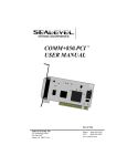
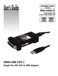
SeaLINK+232
USER MANUAL
TM
Part # 2105
Sealevel Systems, Inc
155 Technology Place
P.O. Box 830
Liberty, SC 29657 USA
Phone: (864) 843-4343
FAX:
(864) 843-3067
www.sealevel.com
Contents
INTRODUCTION......................................................................... 1
OVERVIEW ................................................................................................1
W HAT ’S INCLUDED ................................................................................1
INSTALLATION.......................................................................... 2
OPERATING SYSTEM INSTALLATION .................................................2
SYSTEM INSTALLATION ........................................................................2
TECHNICAL DESCRIPTION ........................................................ 6
FEATURES.................................................................................................6
CONNECTOR PIN A SSIGNMENTS (DB9 M ALE)...................................6
DB-9 (EIA-574 DTE) (DB9 MALE)................................................6
SPECIFICATIONS ....................................................................... 7
ENVIRONMENTAL SPECIFICATIONS ....................................................7
M ANUFACTURING...................................................................................7
POWER CONSUMPTION ..........................................................................7
M EAN TIME BETWEEN FAILURES (MTBF)........................................7
PHYSICAL DIMENSIONS..........................................................................7
APPENDIX A - TROUBLESHOOTING........................................... 8
APPENDIX B - HOW TO GET ASSISTANCE................................ 9
APPENDIX C - ELECTRICAL INTERFACE.................................. 10
RS-232 .....................................................................................................10
APPENDIX D - ASYNCHRONOUS COMMUNICATIONS .............. 11
APPENDIX E - COMPLIANCE NOTICES .................................... 12
FEDERAL COMMUNICATIONS COMMISSION STATEMENT ............12
EMC DIRECTIVE STATEMENT ...........................................................12
WARRANTY............................................................................. 13
Figure 1 - Asynchronous Communications Bit Diagram............................ 11
© 2001b Sealevel Systems, Incorporated. All rights reserved.
Introduction
Introduction
Overview
The Sealevel Systems SeaLINK+232 equips the PC with 1 USB to RS-232
Asynchronous serial port providing a versatile interface for common RS-232
needs (i.e. modem, mouse and plotter). The advantage of this product over more
traditional approaches is that it doesn’t require opening the computer case, nor
does it require resources such as I/O ports or IRQ’s. It does require a system that
supports USB both in terms of hardware and operating system.
What’s Included
The SeaLINK+232 is shipped with the following items. If any of these items is
missing or damaged, contact the supplier.
•
•
•
SeaLINK+232 USB to RS-232 Serial I/O Adapter
Sealevel Software
User Manual
Sealevel Systems SeaLINK+232
Page 1
Installation
Installation
Operating System Installation
Choose Install Software at the beginning of the CD and select the Serial I/O
software drivers and install SeaCOM.
System Installation
The screen captures below are taken from a Windows ME installation. Your
particular operating system may differ slightly from what is shown based on your
version of Windows.
The SeaLINK+232 can be connected to any Upstream Type “A” port either at
the PC host or an Upstream Hub. The SeaLINK+232 is hot-pluggable, meaning
there is no need to power down your computer prior to installation. The
SeaLINK+232 requires no user hardware configuration since there are no
jumpers present on the card.
1.
Connect SeaLINK+232 to an Upstream Host or Hub.
This indicates that the system has recognized the new device and will now
proceed to locate a driver.
Sealevel Systems SeaLINK+232
Page 2
Installation
Since you have already installed the software by running “Setup”, simply click
“Next” to proceed. The drivers that were installed during setup will automatically
be used to configure the adapter.
Sealevel Systems SeaLINK+232
Page 3
Installation
Windows has now located a driver and installed the software. Click “Finish” to
proceed. You should see one more “New Hardware Found”, indicating the actual
port being created. If you view your systems’ Device Manager at this point, you
should have a new “COM” port in the Ports (COM & LPT) Device Class. It
should look similar to the screen shot on the following page.
Sealevel Systems SeaLINK+232
Page 4
Installation
You can access your new COM: port by using the assigned COM: identifier
shown above. In this case, it is COM4: but this assignment will vary from system
to system. At this point, the hardware is recognized. To verify operation use
Sealevel Systems supplied WinSSD diagnostic utility. WinSSD can be found in
the Start, Programs group.
Sealevel Systems SeaLINK+232
Page 5
Technical Description
Technical Description
The SeaLINK+232 utilizes a USB UART. This chip features programmable baud
rate, data format, 128 byte Dual Port TX Buffer, and 384 byte Dual Port RX Buffer.
The RS-232 transceiver supports data rates up to 460.8K baud. Refer to Appendix
C for cable length limitations.
Features
•
Hot-Pluggable device that doesn’t require opening the case
•
No system resources are required (i.e. I/O ports or IRQ’s)
•
LED status indicators for “TX”, and “RX”
Connector Pin Assignments (DB9 Male)
DB-9 (EIA-574 DTE) (DB9 MALE)
Signal
GND
TD
RTS
DTR
RD
CTS
DSR
DCD
RI
Name
Ground
Transmit Data
Request To Send
Data Terminal Ready
Receive Data
Clear To Send
Data Set Ready
Data Carrier Detect
Ring Indicator
Pin #
5
3
7
4
2
8
6
1
9
Mode
Output
Output
Output
Input
Input
Input
Input
Input
Technical Note: Please terminate any control signals that are not going to be
used. The most common way to do this is connect RTS to CTS and RI. Also,
connect DCD to DTR and DSR. Terminating these pins, if not used, will help
insure you get the best performance from your adapter.
Sealevel Systems SeaLINK+232
Page 6
Specifications
Specifications
Environmental Specifications
Specification
Temperature Range
Humidity Range
Operating
0º to 50º C
(32º to 122º F)
10 to 90% R.H.
Non-Condensing
Storage
-20º to 70º C
(-4º to 158º F)
10 to 90% R.H.
Non-Condensing
Manufacturing
•
All Sealevel Systems Printed Circuit boards are built to UL 94V0 rating and
are 100% electrically tested. These printed circuit boards are solder mask
over bare copper or solder mask over tin nickel.
Power Consumption
Supply line
Rating
+5 VDC
100 mA
Mean Time Between Failures (MTBF)
Greater than 150,000 hours. (Calculated)
Physical Dimensions
Package Length
Package Width
Package Height
Sealevel Systems SeaLINK+232
2.14 inches
1.4 inches
.63 inches
(5.44 cm)
(3.55 cm)
(1.60 cm)
Page 7
Appendix A – Troubleshooting
Appendix A - Troubleshooting
Serial Utility test software is supplied with the Sealevel Systems adapter and will
be used in the troubleshooting procedures. Using this software and following
these simple steps, most common problems can be eliminated without the need to
call Technical Support.
1.
If your adapter isn’t working, first check to make sure that USB support is
enabled in the System BIOS and it is functioning properly in the operating
system. This can be done by using either the Windows 98/ME or Windows
2000 Device Manager.
2.
Ensure that the Sealevel Systems software has been installed on the machine
so that the necessary files are in place to complete the installation.
3.
Use Sealevel’s WinSSD utility and the supplied loopback plug to check
communications. The supplied loopback plug connects TD to RD. If you
decide to test the Modem Control Signals, a full pin loopback plug will be
required. Details on loopback plugs are included within WinSSD. Contact
Sealevel Systems if you need further assistance
4.
When testing the SeaLINK+232 in loopback mode, you should see both the
TX and RX LED’s flashing as well as seeing echoed data on the screen. The
loopback test first transmits a HEX pattern, 55AA, and then an ASCII string
of data. If this test passes, then the SeaLINK+232 is ready for use in your
application.
Sealevel Systems SeaLINK+232
Page 8
Appendix B – How To Get Assistance
Appendix B - How To Get Assistance
Please refer to
Appendix A - Troubleshooting prior to calling Technical Support.
1.
Read this manual thoroughly before attempting to install the
adapter in your system.
2.
When calling for technical assistance, please have your user
manual and current adapter settings. If possible, please have the
adapter connected in a computer ready to run diagnostics.
3.
Sealevel Systems maintains a home page on the Internet. Our home
page address is www.sealevel.com. The latest software updates
and newest manuals are available via our FTP site, accessible from
our home page.
4.
Technical support is available Monday through Friday from 8:00
a.m. to 5:00 p.m. Eastern time. Technical support can be reached at
(864) 843-4343.
RETURN AUTHORIZATION MUST BE OBTAINED FROM SEALEVEL
SYSTEMS BEFORE RETURNED MERCHANDISE WILL BE ACCEPTED.
AUTHORIZATION CAN BE OBTAINED BY CALLING SEALEVEL SYSTEMS
AND REQUESTING A RETURN MERCHANDISE AUTHORIZATION (RMA)
NUMBER.
Sealevel Systems SeaLINK+232
Page 9
Appendix C - Electrical Interface
Appendix C - Electrical Interface
RS-232
Quite possibly the most widely used communication standard is RS-232. This
implementation has been defined and revised several times and is often referred
to as RS-232 or EIA/TIA-232. The IBM PC computer defined the RS-232 port on a
9 pin D sub connector and subsequently the EIA/TIA approved this
implementation as the EIA/TIA-574 standard. This standard is defined as the
9-Position Non-Synchronous Interface between Data Terminal Equipment and
Data Circuit-Terminating Equipment Employing Serial Binary Data
Interchange. Both implementations are in wide spread use and will be referred to
as RS-232 in this document. RS-232 is capable of operating at data rates up to 20
Kbps at distances less than 50 ft. The absolute maximum data rate may vary due
to line conditions and cable lengths. RS-232 is a single ended or unbalanced
interface, meaning that a single electrical signal is compared to a common signal
(ground) to determine binary logic states. The RS-232 and the EIA/TIA-574
specification define two types of interface circuits, Data Terminal Equipment
(DTE) and Data Circuit-Terminating Equipment (DCE). The SeaLINK+232 is a
DTE device.
Sealevel Systems SeaLINK+232
Page 10
Appendix D - Asynchronous Communications
Appendix D - Asynchronous Communications
Serial data communications implies that individual bits of a character are
transmitted consecutively to a receiver that assembles the bits back into a
character. Data rate, error checking, handshaking, and character framing
(start/stop bits) are pre-defined and must correspond at both the transmitting
and receiving ends.
Asynchronous communications is the standard means of serial data
communication for PC compatibles and PS/2 computers. The original PC was
equipped with a communication or COM: port that was designed around an 8250
Universal Asynchronous Receiver Transmitter (UART). This device allows
asynchronous serial data to be transferred through a simple and straightforward
programming interface. Character boundaries for asynchronous communications
are defined by a starting bit followed by a pre-defined number of data bits (5, 6, 7,
or 8). The end of the character is defined by the transmission of a pre-defined
number of stop bits (usually 1, 1.5 or 2). An extra bit used for error detection is
often appended before the stop bits.
Idle state of
line
5 to 8 Data Bits
Odd, Even
or
Unused
Remain Idle or
next start bit
1
P
BIT
STOP
0
1
1.5
2
Figure 1 - Asynchronous Communications Bit Diagram
This special bit is called the parity bit. Parity is a simple method of determining if
a data bit has been lost or corrupted during transmission. There are several
methods for implementing a parity check to guard against data corruption.
Common methods are called (E)ven Parity or (O)dd Parity. Sometimes parity is
not used to detect errors on the data stream. This is refereed to as (N)o parity.
Because each bit in asynchronous communications is sent consecutively, it is
easy to generalize asynchronous communications by stating that each character
is wrapped (framed) by pre-defined bits to mark the beginning and end of the
serial transmission of the character. The data rate and communication parameters
for asynchronous communications have to be the same at both the transmitting
and receiving ends. The communication parameters are baud rate, parity, number
of
data
bits
per
character,
and
stop
bits
(i.e. 9600,N,8,1).
Sealevel Systems SeaLINK+232
Page 11
Appendix E - Compliance Notices
Appendix E - Compliance Notices
Federal Communications Commission Statement
FCC - This equipment has been tested and found to comply with the limits for
Class A digital device, pursuant to Part 15 of the FCC Rules. These limits are
designed to provide reasonable protection against harmful interference when the
equipment is operated in a commercial environment. This equipment generates,
uses, and can radiate radio frequency energy and, if not installed and used in
accordance with the instruction manual, may cause harmful interference to radio
communications. Operation of this equipment in a residential area is likely to
cause harmful interference. In such case the user will be required to correct the
interference at his own expense.
EMC Directive Statement
Products bearing the CE Label fulfill the requirements of
the EMC directive (89/336/EEC) and of the low-voltage
directive (73/23/EEC) issued by the European Commission.
To obey these directives, the following European
standards must be met:
EN55022 Class B - ‘Limits and methods of measurement of
radio
interference characteristics of information technology equipment’
EN55024-‘Information
technology
equipment
characteristics Limits and methods of measurement.
Immunity
EN60950 (IEC950) - ‘Safety of information
equipment, including electrical business equipment’
technology
Always use cabling provided with this product if possible. If no cable is
provided or if an alternate cable is required, use high quality shielded cabling to
maintain compliance with EMC directives.
Sealevel Systems SeaLINK+232
Page 12
Warranty
Warranty
Sealevel Systems, Inc. provides a lifetime warranty for this product. Should this
product fail to be in good working order at any time during this period, Sealevel
Systems will, at it's option, replace or repair it at no additional charge except as
set forth in the following terms. This warranty does not apply to products
damaged by misuse, modifications, accident or disaster.
Sealevel Systems assumes no liability for any damages, lost profits, lost savings
or any other incidental or consequential damage resulting from the use, misuse
of, or inability to use this product. Sealevel Systems will not be liable for any
claim made by any other related party.
RETURN AUTHORIZATION MUST BE OBTAINED FROM SEALEVEL
SYSTEMS BEFORE RETURNED MERCHANDISE WILL BE ACCEPTED.
AUTHORIZATION CAN BE OBTAINED BY CALLING SEALEVEL SYSTEMS
AND REQUESTING A RETURN MERCHANDISE AUTHORIZATION (RMA)
NUMBER.
Sealevel Systems, Incorporated
155 Technology Place
P.O. Box 830
Liberty, SC 29657 USA
(864) 843-4343 FAX: (864) 843-3067
www.sealevel.com
email: [email protected]
Technical Support is available from 8 a.m. to 5 p.m. Eastern time.
Monday - Friday
Trademarks
Sealevel Systems, Incorporated acknowledges that all trademarks referenced in
this manual are the service mark, trademark, or registered trademark of the
respective company.
SeaLINK+232 is a trademark of Sealevel Systems, Incorporated.
Sealevel Systems SeaLINK+232
Page 13