1
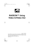
SECOND
OPINION
Computer Based Alternatives
1624 West 240th Street, Harbor City, CA 90710
Voice: (310) 534-2444 • Fax: (310) 534-2446
Second Opinion Software
1.0 Installing the Video Capture Board
Contents
1.0 Installing the Video Capture Board......................................................... 1
2.0 Connecting to a Video Device................................................................... 2
3.0 Configuring the Board for the First Time............................................... 3
4.0 Video Capture Board Options.................................................................. 4
APPENDICES................................................................................................... 7
Appendix A - Troubleshooting............................................................... 7
Date: 02/23/96
Computer Based Alternatives
i
Second Opinion Software
Video Capture Board/Installation
1.0 Installing the Video Capture Board
Before installing the video capture board, turn off the power to your PC, and
remove the cover. Since the board is sensitive to static electricity, we
recommend that before you remove it from its protective anti-static bag, you
touch the chassis with your hand to discharge any static electricity.
A u d io o u t
A u d io in Vid e o in
L
R
Y
V G A d isp lay
ad ap ter
V G A Loop
C ab le
C
Vid eo c ap tu re
b o ard
O u tp u t to V G A
m o n ito r
When installing the board in your PC, we recommend that the board be placed
in the slot next to the VGA board.
The video capture board comes with a VGA Loop Cable. The cable has a 15
pin D-type (VGA-style) connector at one end and a 26 pin D-type connector at
the other end. The 26 pin D-type connector is plugged into the matching
connector on the video capture board. The 15 pin D-type connector is plugged
into the VGA board output. The monitor is then plugged into the video capture
board.
Computer Based Alternatives
1
Second Opinion Software
Video Capture Board/Installation
2.0 Connecting to a Video Device
Composite Video Installation
Most video devices have at least one female RCA style push-on connector
labeled “Video Out”. To connect to the video capture board, use a shielded
video cable with male connectors on both ends. Connect from the “Video Out”
jack on your VCR or camcorder to the “Y” (Composite 1) or “C” (Composite
2) connector on the VGA Loop Cable.
S-Video Cable Installation
The S-Video cable required has a 4 pin mini DIN plug on one end and two
RCA style plugs on the other. This cable will connect the S-Video output on a
high end VCR or camcorder to the “Y” and “C” connectors on the VGA Loop
Cable. S-Video is different from the video output provided on most VCRs
(called composite video) in that in S-Video, the black/white information and
the color information are sent to the board over two separate cables.
NOTE: Most VCRs and camcorders do not support an S-Video output. Please
consult your user’s manual if you believe your VCR or camcorder should have
an S-Video connector and you cannot find it.
Sound Cable Installed (Requires a Sound Card)
If you plan to listen to sound from the video through your computer’s sound
card, you need to make an additional connection. Connect from the “Audio
Out” jack on the VCR or camcorder to the left (“L”) and right (“R”) connectors
on the VGA Loop Cable. The Audio output on the VGA Loop Cable uses a
1/8 inch stereo jack to output sound to a sound card or amplified speakers. A
short adapter cable is supplied (male 1/8 inch connectors on each end) for
connecting to the Line Input of most sound cards.
WARNING: The Audio out connector provided with your video capture
board is stereo. DO NOT use a monaural plug. The use of a monaural plug
could cause damage to your board. A Stereo-to-Mono splitter can be used to
adapt the 1/8 inch stereo jack to fit two 1/8 inch monaural plugs.
Computer Based Alternatives
2
Second Opinion Software
Video Capture Board/Installation
3.0 Configuring the Board for the First Time
1. Start the Second Opinion application. Then select Options from the File
Menu, and click on the Capture tab.
2. Connect a video device to the capture board, and turn it on so that it
provides a video signal (if it is a VCR, play a tape with content).
3. Select the appropriate video source (Composite 1, Composite 2, or
S-Video).
4. Select the video format (NTSC, PAL, etc.)
5. Click on Configure. The Hardware Configuration dialog will open (see
Section 4 for information on configuring the board).
6. Click on Alignment. The Video window and the Configure Display dialog
will open. Avoid clicking on the Video window; if you do, it will hide the
Configure Display dialog. You will need to change the video window’s
size to see the Configure Display dialog again. Adjust the alignment of the
video as needed (see Section 4 for information on adjusting alignment).
7. Click on Color. The Video window and the Adjust Color dialog will open.
Avoid clicking on the Video window; if you do, it will hide the Adjust
Color dialog. You will need to change the video window’s size to see the
Computer Based Alternatives
3
Second Opinion Software
Video Capture Board/Installation
Adjust Color dialog again. Adjust the color as needed (see Section 4 for
the information on adjusting color).
4.0 Video Capture Board Options
To change the video capture board settings, choose Options from the File menu
and select the Capture tab.
Configure
The Configure button opens the Hardware Configuration dialog box, which is
used to configure the software to match the video capture board. You should
not need to change the I/O port, IRQ level, Tuner Type, or Interleave.
Memory Base - This is the starting address of the video RAM on the capture
board. This address is used when the software needs to access the video image
for capturing to Second Opinion. If your system contains memory or I/O
devices at the same address, there will be problems with the video capture
function. Change the memory base to a clear area in your memory map.
The memory base can be set at an address between 640K and 1024K or from
one megabyte to sixteen megabytes. A memory overlap or conflict occurs, for
example, if a system has 16 megabytes of RAM and the capture board is set at
an address of 14 megs. This will cause a 2 megabyte memory overlap,
resulting in a saved image consisting of no video information. To correct this
type of problem, set the memory base to an address that will not conflict
(i.e., B000). Systems that employ a VGA controller, in addition to a
monochrome board will have problems with this address (in this case set the
buffer to E800). When the video capture board is used with some VESA Local
Bus cards, the buffer address must be set to D000, with this region excluded in
Computer Based Alternatives
4
Second Opinion Software
Video Capture Board/Installation
EMM386.SYS or QEMM386.SYS. Otherwise, capturing images may not be
possible.
Color
The Color button opens the Adjust Color dialog box.
This dialog box allows the changing of Brightness, Saturation, Contrast and
Hue. Like the controls on a color TV set, these settings can be used to create a
more realistic visual image. If you are unhappy with the settings, start again by
clicking on the Default button.
Align
The Align button opens the Configure Display dialog box.
This dialog box sets the framing of the video within the Live Video window.
Sometimes you may see the video out of alignment (screen shifted to the right
or left; a magenta bar appearing along the top, bottom and side edges of the
window). The alignment may be fixed by using the following items:
Window X - Helps eliminate vertical magenta bars along the left and right
hand sides of the video.
Window Y - Helps eliminate horizontal magenta bars along the top and
bottom edges of the video.
Computer Based Alternatives
5
Second Opinion Software
Video Capture Board/Installation
Width - The width control configures the width of the image in the Live Video
window. If the image appears pushed to one side, use this control to fit the
image properly into the window.
On the bottom of the Configure Display dialog box are two boxes: Vertical
Sync and Interlace.
Vertical Sync - This setting is used to activate special hardware on the capture
board when high-resolution VGA boards are used. If your VGA controller’s
refresh rate is set to 60hz, select < 72hz.
Interlace - Use this box to select between Interlace or Non-Interlaced modes.
The default configuration is Auto. This setting automatically detects which
mode the video board is in and should not have to be changed (some VGA
drivers need to set this option manually for 800 x 600 or 1024 x 768 modes).
Computer Based Alternatives
6
Second Opinion Software
Video Capture Board/Installation
APPENDICES
Appendix A - Troubleshooting
Many problems are caused when the video cables are connected incorrectly to
the capture board. Please recheck your cables to ensure that they are properly
connected.
This section lists commonly asked questions that arise during installation of the
capture board:
Why can’t I capture a video image?
The video board has a frame buffer to “capture” a video image. This frame
buffer might have an address conflict with some PC’s, resulting in the board’s
not being able to capture images. To test to see if the board is at the correct
address, run Second Opinion, open a sample patient, click the Capture button,
and then click Capture in the Live Video window. Then exit the Live Video
window. If the captured image appears on the Second Opinion desktop, the
memory base address is correct. If not, the following procedure can be used to
change the address:
1. Click on Options from the File menu, and choose the Configure button
from the Capture tab. Change the setting of Memory Base to another
address. We suggest D000 as the next likely address to try.
You must then close Second Opinion, and exit Windows.
2. The CONFIG.SYS file in the C:\ directory must be modified. If you are
using EMM386, there is a statement that normally says:
DEVICE=EMM386.EXE
This must be changed to exclude the 32K memory range used by the video
board. For example, if you chose D000, edit this line so it reads:
DEVICE=EMM386.EXE X=d000-d7ff
If you are using another expanded memory manager such as QEMM,
instead of EMM386, the memory range must be excluded.
Computer Based Alternatives
7
Second Opinion Software
Video Capture Board/Installation
You can now reboot your computer (Ctrl+Alt+Del) and then run Windows and
Second Opinion. Now retest the video capture. If you still cannot see the
captured image on the Second Opinion desktop, then you will have to rerun the
above procedure, trying a different memory base address.
NOTE: Some PCs shadow or cache all of the memory between 640K and
1MB. If your PC does this, to properly save an image the Memory Base
address must be uncached or the shadow disabled. After setting the Memory
Base to D000, this can be done in your PC’s Advanced BIOS setup program:
DisableShadowMemory Size = 32K
DisableShadowMemory Base = D000H
How do I adjust my window to eliminate the magenta
bars around the picture?
The adjustments for the window alignment are located in
File/Options/Capture/Alignment. The best procedure for adjusting the
alignment is the following:
1. Window X - Set window X so the magenta bar on the left hand side is as
small as possible (cannot be less than 1 pixel wide). Make the setting one
click lower, until the magenta bar on the left hand side of the stops getting
smaller.
2. Window Width - Adjust the width until the image fits exactly inside the
window with no magenta bar visible to the right. You might now have to
readjust Window X.
3. Window Y - Now you can adjust the Y position so that there is no magenta
on the top or bottom of the window.
No video appears on the VGA monitor.
This can occur when either the VGA monitor cable is not plugged into the
capture board or the VGA Loop Cable is loose or not plugged into the capture
board and VGA board properly.
Live Video window shows only magenta.
This can occur when either the VGA monitor cable is plugged into your VGA
board instead of the capture board or when the video window is out of
alignment (that is, the video is outside the visible window). Follow the
alignment procedures to correct this problem.
Computer Based Alternatives
8
Second Opinion Software
Video Capture Board/Installation
Live Video window shows only black.
There is no external video source connected to the capture board, or you
connected the audio from the video source to the video input connectors, or
your video source is turned off.
I get a black and white picture.
The video source or format or both are not set correctly, or the video cable is
plugged into the wrong video input connector. If you are using S-Video, try
reversing the two (Y and C) video cables.
The Live Video image contains horizontal jitter.
The video capture board may be having a hard time locking with the video
signal. First change the size of the Live Video window. If nothing improves,
reset the board by closing and then re-opening the Live Video window while
the video is playing. If there is still no improvement, check the quality of your
video source.
The captured image is not clean.
You may be running out of memory. Close some of the images on the screen.
The video capture board may also not be configured properly.
Computer Based Alternatives
9