1
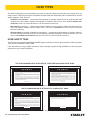
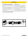
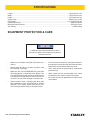
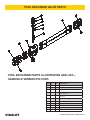
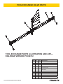
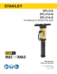
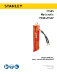
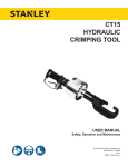
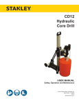
TOOL
EXCHANGE VALVE
USER MANUAL
Safety, Operation and Maintenance
© 2014 Stanley Black & Decker, Inc.
New Britain, CT 06053
U.S.A.
69723 10/2014 Ver. 3
TABLE OF CONTENTS
SAFETY SYMBOLS...................................................................................................................................................4
SAFETY PRECAUTIONS...........................................................................................................................................5
HOSE TYPES.............................................................................................................................................................6
HTMA REQUIREMENTS............................................................................................................................................7
OPERATION...............................................................................................................................................................8
SPECIFICATIONS....................................................................................................................................................10
TOOL EXCHANGE PARTS ILLUSTRATION AND LIST—HANDHELD VERSION P/N 67005................................ 11
TOOL EXCHANGE PARTS ILLUSTRATION AND LIST—RAILROAD VERSION P/N 69722................................. 12
IMPORTANT
To fill out a Product Warranty Validation form, and for information on your warranty,
visit Stanleyhydraulics.com and select the Company tab, Warranty.
(NOTE: The warranty Validation record must be submitted to validate the warranty).
SERVICING: This manual contains safety, operation, and routine maintenance instructions. Stanley Hydraulic Tools
recommends that servicing of hydraulic tools, other than routine maintenance, must be performed by an authorized
and certified dealer. Please read the following warning.
WARNING
SERIOUS INJURY OR DEATH COULD RESULT FROM THE IMPROPER REPAIR OR
SERVICE OF THIS TOOL.
REPAIRS AND / OR SERVICE TO THIS TOOL MUST ONLY BE DONE BY AN
AUTHORIZED AND CERTIFIED DEALER.
For the nearest authorized and certified dealer, call Stanley Hydraulic Tools at the number listed on the back of this
manual and ask for a Customer Service Representative.
Tool Exchange Valve User Manual ◄ 3
SAFETY SYMBOLS
Safety symbols and signal words, as shown below, are used to emphasize all operator, maintenance and repair actions which, if not strictly followed, could result in a life-threatening situation, bodily injury or damage to equipment.
This is the safety alert symbol. It is used to alert you to potential personal injury
hazards. Obey all safety messages that follow this symbol to avoid possible
injury or death.
DANGER
This safety alert and signal word indicate an imminently hazardous situation
which, if not avoided, will result in death or serious injury.
WARNING
This safety alert and signal word indicate a potentially hazardous situation
which, if not avoided, could result in death or serious injury.
CAUTION
This safety alert and signal word indicate a potentially hazardous situation
which, if not avoided, could result in death or serious injury.
CAUTION
This signal word indicates a potentially hazardous situation which, if not avoided, may result in property damage.
NOTICE
This signal word indicates a situation which, if not avoided, will result in damage
to the equipment.
IMPORTANT
This signal word indicates a situation which, if not avoided, may result in damage to the equipment.
Always observe safety symbols. They are included for your safety and for the protection of the tool.
LOCAL SAFETY REGULATIONS
Enter any local safety regulations here. Keep these instructions in an area accessible to the operator and maintenance personnel.
4 ► Tool Exchange Valve User Manual
SAFETY PRECAUTIONS
Tool operators and maintenance personnel must always
comply with the safety precautions given in this manual
and on the stickers and tags attached to the tool and
hose.
These safety precautions are given for your safety. Review them carefully before operating the tool and before
performing general maintenance or repairs.
Supervising personnel should develop additional precautions relating to the specific work area and local
safety regulations. If so, place the added precautions in
the space provided on the previous page.
This valve will provide safe and dependable service if
operated in accordance with the instructions given in
this manual. Read and understand this manual and any
stickers and tags attached to the tool and hose before
operation. Failure to do so could result in personal injury
or equipment damage.
•
The operator must start in a work area without bystanders. Flying debris can cause serious injury.
•
Do not operate the valve unless thoroughly trained
or under the supervision of an instructor. Establish
a training program for all operators to ensure safe
operation.
•
Always wear safety equipment such as goggles, ear
and head protection, and safety shoes at all times
when operating the valve. Use gloves and aprons
when necessary.
•
The operator must be familiar with all prohibited
work areas such as excessive slopes and dangerous terrain conditions.
•
Maintain proper footing and balance at all times.
•
Do not inspect or clean the valve while the hydraulic
power source is connected. Accidental engagement
can cause serious injury.
•
Do not operate the valve at oil temperatures above
140°F/60°C. Operation at higher temperatures can
cause higher than normal temperatures at the valve
which can result in operator discomfort.
•
Do not operate a damaged, improperly adjusted, or
incompletely assembled valve.
•
Always use accessories that conform to the specifications given in the OPERATION section of this
manual.
•
When working near electrical conductors, always
assume that all conductors are energized and that
insulation, clothing and hoses can conduct electricity. Use hose labeled and certified as non-conductive.
•
To avoid personal injury or equipment damage, all
valve repair, maintenance and service must only be
performed by authorized and properly trained personnel.
•
Do not carry the valve by hoses.
Tool Exchange Valve User Manual ◄ 5
HOSE TYPES
The rated working pressure of the hydraulic hose must be equal to or higher than the relief valve setting on the hydraulic system. There are three types of hydraulic hose that meet this requirement and are authorized for use with
Stanley Hydraulic Tools. They are:
Certified non-conductive — constructed of thermoplastic or synthetic rubber inner tube, synthetic fiber braid
reinforcement, and weather resistant thermoplastic or synthetic rubber cover. Hose labeled certified nonconductive is the only hose authorized for use near electrical conductors.
Wire-braided (conductive) — constructed of synthetic rubber inner tube, single or double wire braid reinforcement, and weather resistant synthetic rubber cover. This hose is conductive and must never be used near
electrical conductors.
Fabric-braided (not certified or labeled non-conductive) — constructed of thermoplastic or synthetic rubber inner tube, synthetic fiber braid reinforcement, and weather resistant thermoplastic or synthetic rubber cover. This
hose is not certified non-conductive and must never be used near electrical conductors.
HOSE SAFETY TAGS
To help ensure your safety, the following DANGER tags are attached to all hose purchased from Stanley Hydraulic
Tools. DO NOT REMOVE THESE TAGS.
If the information on a tag is illegible because of wear or damage, replace the tag immediately. A new tag may be
obtained from your Stanley Distributor.
D A N G E R
D A N G E R
1.
FAILURE TO USE HYDRAULIC HOSE LABELED AND CERTIFIED AS NON-CONDUCTIVE
WHEN USING HYDRAULIC TOOLS ON OR NEAR ELECTRIC LINES MAY RESULT IN
DEATH OR SERIOUS INJURY.
FOR PROPER AND SAFE OPERATION MAKE SURE THAT YOU HAVE BEEN PROPERLY TRAINED IN CORRECT PROCEDURES REQUIRED FOR WORK ON OR AROUND
ELECTRIC LINES.
2.
BEFORE USING HYDRAULIC HOSE LABELED AND CERTIFIED AS NON-CONDUCTIVE
ON OR NEAR ELECTRIC LINES. WIPE THE ENTIRE LENGTH OF THE HOSE AND FITTING WITH A CLEAN DRY ABSORBENT CLOTH TO REMOVE DIRT AND MOISTURE AND
TEST HOSE FOR MAXIMUM ALLOWABLE CURRENT LEAKAGE IN ACCORDANCE WITH
SAFETY DEPARTMENT INSTRUCTIONS.
3.
DO NOT EXCEED HOSE WORKING PRESSURE OR ABUSE HOSE. IMPROPER USE
OR HANDLING OF HOSE COULD RESULT IN BURST OR OTHER HOSE FAILURE.
KEEP HOSE AS FAR AWAY AS POSSIBLE FROM BODY AND DO NOT PERMIT DIRECT
CONTACT DURING USE. CONTACT AT THE BURST CAN CAUSE BODILY INJECTION
AND SEVERE PERSONAL INJURY.
4.
HANDLE AND ROUTE HOSE CAREFULLY TO AVOID KINKING, ABRASION, CUTTING, OR
CONTACT WITH HIGH TEMPERATURE SURFACES. DO NOT USE IF KINKED. DO NOT
USE HOSE TO PULL OR LIFT TOOLS, POWER UNITS, ETC.
5.
CHECK ENTIRE HOSE FOR CUTS CRACKS LEAKS ABRASIONS, BULGES, OR DAMAGE TO COUPLINGS IF ANY OF THESE CONDITIONS EXIST, REPLACE THE HOSE
IMMEDIATELY. NEVER USE TAPE OR ANY DEVICE TO ATTEMPT TO MEND THE HOSE.
6.
AFTER EACH USE STORE IN A CLEAN DRY AREA.
SEE OTHER SIDE
SIDE 1
SEE OTHER SIDE
(Shown smaller than actual size)
DO NOT REMOVE THIS TAG
DO NOT REMOVE THIS TAG
THE TAG SHOWN BELOW IS ATTACHED TO “CERTIFIED NON-CONDUCTIVE” HOSE
SIDE 2
D A N G E R
D A N G E R
1.
DO NOT USE THIS HYDRAULIC HOSE ON OR NEAR ELECTRIC LINES. THIS HOSE IS
NOT LABELED OR CERTIFIED AS NON-CONDUCTIVE. USING THIS HOSE ON OR NEAR
ELECTRICAL LINES MAY RESULT IN DEATH OR SERIOUS INJURY.
5.
CHECK ENTIRE HOSE FOR CUTS CRACKS LEAKS ABRASIONS, BULGES, OR DAMAGE TO
COUPLINGS IF ANY OF THESE CONDITIONS EXIST, REPLACE THE HOSE IMMEDIATELY.
NEVER USE TAPE OR ANY DEVICE TO ATTEMPT TO MEND THE HOSE.
2.
FOR PROPER AND SAFE OPERATION MAKE SURE THAT YOU HAVE BEEN PROPERLY
TRAINED IN CORRECT PROCEDURES REQUIRED FOR WORK ON OR AROUND ELECTRIC LINES.
6.
AFTER EACH USE STORE IN A CLEAN DRY AREA.
3.
DO NOT EXCEED HOSE WORKING PRESSURE OR ABUSE HOSE. IMPROPER USE OR
HANDLING OF HOSE COULD RESULT IN BURST OR OTHER HOSE FAILURE. KEEP HOSE
AS FAR AWAY AS POSSIBLE FROM BODY AND DO NOT PERMIT DIRECT CONTACT
DURING USE. CONTACT AT THE BURST CAN CAUSE BODILY INJECTION AND SEVERE
PERSONAL INJURY.
4.
HANDLE AND ROUTE HOSE CAREFULLY TO AVOID KINKING, CUTTING, OR CONTACT
WITH HIGH TEMPERATURE SURFACES. DO NOT USE IF KINKED. DO NOT USE HOSE TO
PULL OR LIFT TOOLS, POWER UNITS, ETC.
SEE OTHER SIDE
SEE OTHER SIDE
SIDE 1
SIDE 2
(Shown smaller than actual size)
6 ► Tool Exchange Valve User Manual
DO NOT REMOVE THIS TAG
DO NOT REMOVE THIS TAG
THE TAG SHOWN BELOW IS ATTACHED TO “CONDUCTIVE” HOSE.
HTMA / EHTMA REQUIREMENTS
HTMA / EHTMA REQUIREMENTS
HTMA
HYDRAULIC SYSTEM REQUIREMENTS
TYPE I
Nominal Operating Pressure
(at the power supply outlet)
4-6 gpm
(15-23 lpm)
1500 psi
(103 bar)
TOOL TYPE
TYPE II
TYPE RR
7-9 gpm
(26-34 lpm)
1500 psi
(103 bar)
9-10.5 gpm
(34-40 lpm)
1500 psi
(103 bar)
System relief valve setting
(at the power supply outlet)
2100-2250 psi
(145-155 bar)
2100-2250 psi
(145-155 bar)
2200-2300 psi
(152-159 bar)
2100-2250 psi
(145-155 bar)
Maximum back pressure
(at tool end of the return hose)
250 psi
(17 bar)
250 psi
(17 bar)
250 psi
(17 bar)
250 psi
(17 bar)
Measured at a max. fluid viscosity of:
(at min. operating temperature)
400 ssu*
400 ssu*
400 ssu*
400 ssu*
(82 centistokes) (82 centistokes) (82 centistokes) (82 centistokes)
Temperature: Sufficient heat rejection
capacity to limit max. fluid temperature to:
(at max. expected ambient temperature)
140° F
(60° C)
Flow Range
140° F
(60° C)
140° F
(60° C)
TYPE III
11-13 gpm
(42-49 lpm)
1500 psi
(103 bar)
140° F
(60° C)
3 hp
5 hp
6 hp
7 hp
Min. cooling capacity at a temperature
(2.24 kW)
(3.73 kW)
(5.22 kW)
(4.47 kW)
difference of between ambient and fluid
40° F
40° F
40° F
40° F
temps
(22° C)
(22° C)
(22° C)
(22° C)
NOTE:
Do not operate the tool at oil temperatures above 140° F (60° C). Operation at higher temperatures can cause operator
discomfort at the tool.
Filter
Min. full-flow filtration
Sized for flow of at least:
(For cold temp. startup and max.
dirt-holding capacity)
25 microns
30 gpm
(114 lpm)
Hydraulic fluid Petroleum based
(premium grade, anti-wear, non-conductive)
Viscosity (at min. and max. operating temps)
100-400 ssu*
25 microns
30 gpm
(114 lpm)
25 microns
30 gpm
(114 lpm)
100-400 ssu*
100-400 ssu*
(20-82 centistokes)
25 microns
30 gpm
(114 lpm)
100-400 ssu*
NOTE:
When choosing hydraulic fluid, the expected oil temperature extremes that will be experienced in service determine the
most suitable temperature viscosity characteristics. Hydraulic fluids with a viscosity index over 140 will meet the requirements
over a wide range of operating temperatures.
*SSU = Saybolt Seconds Universal
EHTMA
HYDRAULIC SYSTEM
REQUIREMENTS
CLASSIFICATION
B
C
D
Nominal Operating Pressure
(at the power supply outlet)
3.5-4.3 gpm
(13.5-16.5 lpm)
1870 psi
(129 bar)
4.7-5.8 gpm
(18-22 lpm)
1500 psi
(103 bar)
7.1-8.7 gpm
(27-33 lpm)
1500 psi
(103 bar)
9.5-11.6 gpm
(36-44 lpm)
1500 psi
(103 bar)
11.8-14.5 gpm
(45-55 lpm)
1500 psi
(103 bar)
System relief valve setting
(at the power supply outlet)
2495 psi
(172 bar)
2000 psi
(138 bar)
2000 psi
(138 bar)
2000 psi
(138 bar)
2000 psi
(138 bar)
Flow Range
NOTE: These are general hydraulic system requirements. See tool specification page for tool specific requirements
Tool Exchange Valve User Manual ◄ 7
OPERATION
PRE-OPERATION PROCEDURES
INSTALLATION
Ensure that you have read and understand the safety
instructions included in this manual before you operate
the valve.
The Tool Exchange Valve is intended to be installed between the tool and the end of the hydraulic hose.
Check whether the valve is damaged. Check that all the
parts are functioning correctly. Check that moving parts
do not become stuck and are not damaged.
DO NOT use the valve if damaged or defective parts are
detected. Damaged or defective parts must be repaired
by a qualified technician.
Using a calibrated flow meter and pressure gauge,
check that the hydraulic power source develops a flow of
4-10.5 gpm/15-40 lpm at 2000 psi/140 bar with a maximum relief pressure not to exceed 2500 psi/170 bar.
POWER
8 ► Tool Exchange Valve User Manual
ON
OFF
TOOL
Connect the Tool Exchange Valve to the hydraulic power supply on the side of the valve labeled “Power” as
shown below. Observe the flow indicators cast into the
valve and stamped on the couplers to ensure that the
flow is in the proper direction.
Connect the Tool Exchange Valve to the tool on the side
of the valve labeled “Tool” as shown below. Observe the
flow indicators cast into the valve and stamped on the
couplers to ensure that the flow is in the proper direction.
OPERATION
OPERATION
The Tool Exchange Valve is intended to function as a
momentary ON/OFF valve that, when plumbed between
a tool and a hydraulic power supply, will allow the end
user to change tools without having to turn off the hydraulic circuit.
Shifting the Tool Exchange Valve’s spool to the ON position will allow the tool to function normally. The hydraulic
oil will flow from the hydraulic power supply through the
valve to the tool. Return oil will flow from the tool through
the valve and back to the hydraulic power supply’s reservoir.
Shifting the Tool Exchange Valve’s spool to the OFF position will disconnect the tool from the hydraulic power
supply. This will allow the end user to remove the tool
and attach an alternate tool. Shifting the Tool Exchange
Valve’s spool to the ON position will allow the alternate
tool to function normally.
CAUTION
With a constant flow (open center) hydraulic power
supply, shifting the Tool Exchange Valve’s spool
to the OFF position will force all the hydraulic flow
through the system’s relief valve.
This valve is intended for tool exchange only and
should not be left in the OFF position for more than
30 seconds. Failure to heed this warning can result
in seal failure, excessive heat, and damage to the
tool and hydraulic power supply.
The Tool Exchange Valve should not be used as a
tool ON/OFF valve. Use Part Number 38632 In-Line
Valve for those applications.
STORAGE
Replace any damaged or missing safety labels and tags before storing the tool. Clean, dry and lubricate moving parts
before storing the tool. Store the tool in a clean, dry place.
Tool Exchange Valve User Manual ◄ 9
SPECIFICATIONS
Length..........................................................................................................................................3.000 inches/7.6 cm
Width............................................................................................................................................1.500 inches/3.8 cm
Height...........................................................................................................................................3.750 inches/9.5 cm
System Type................................................................................................................................. HTMA Type I, II, RR
Flow Range...............................................................................................................................4-10.5 gpm/15-40 lpm
Operating Pressure........................................................................................................................... 2000 psi/140 bar
Maximum Relief Pressure................................................................................................................. 2500 psi/170 bar
Tool Porting.......................................................................................................................................... -8 SAE O-Ring
EQUIPMENT PROTECTION & CARE
NOTICE
In addition to the Safety Precautions found in
this manual, observe the following for equipment
protection and care.
•
Make sure all couplers are wiped clean before connection.
•
Always store the valve in a clean dry space, safe
from damage or pilferage.
•
Make sure the circuit PRESSURE hose (with male
quick disconnect) is connected to the IN port. The
circuit RETURN hose (with female quick disconnect)
is connected to the opposite port. Do not reverse circuit flow. This can cause damage to internal seals.
•
Always replace hoses, couplings and other parts
with replacement parts recommended by Stanley
Hydraulic Tools. Supply hoses must have a minimum working pressure rating of 2500 psi/172 bar.
10 ► Tool Exchange Valve User Manual
•
Do not exceed the rated flow (see Specifications in
this manual for correct flow rate and model number).
Rapid failure of the internal seals may result.
•
Valve repair should be performed by experienced
personnel only.
•
Make certain that the recommended relief valves
are installed in the pressure side of the system.
•
Do not use the valve for applications for which it was
not intended.
TOOL EXCHANGE VALVE PARTS
8
4
9
3
2
6
7
5
10
11
1
5
4
TOOL EXCHANGE PARTS ILLUSTRATION AND LIST—
HANDHELD VERSION P/N 67005
ITEM
PART
NO.
QTY
DESCRIPTION
1
00936
2
ADAPTER
2
01604
2
O-RING
3
01652
2
HOSE WHIP, 12"
4
03972
2
COUPLER, 3/8 FEMALE, 3/8 NPT FL
FACE SET 03971
5
03973
2
COUPLER, 3/8 MALE, 3/8 NPT FL FACE
SET 03971
6
07224
2
BACK-UP RING
7
07626
2
O-RING
8
56747
2
SEAL WIPER
9
56749
2
SEAL CAP
10
67008
1
VALVE SPOOL
11
69721
1
INLINE CALVE BODY ASSY
Tool Exchange Valve User Manual ◄ 11
TOOL EXCHANGE VALVE PARTS
6
7
8
4
1
2
3
9
10
5
5
4
TOOL EXCHANGE PARTS ILLUSTRATION AND LIST—
RAILROAD VERSION P/N 69722
12 ► Tool Exchange Valve User Manual
ITEM
PART
NO.
QTY
DESCRIPTION
1
01604
2
O-RING
2
07224
2
BACK-UP RING
3
07626
2
O-RING
4
47436
2
COUPLER, 3/8 FEMALE, 3/8 NPT FL
FACE SET 47438
5
47437
2
COUPLER, 3/8 MALE, 3/8 NPT FL FACE
SET 47438
6
56747
2
SEAL WIPER
7
56749
2
SEAL CAP
8
66727
4
HOSE ASSY
9
67008
1
VALVE SPOOL
10
69721
1
TOOL EXCHANGE VALVE
Stanley Hydraulic Tools
3810 SE Naef Road
Milwaukie, Oregon 97267-5698 USA
(503) 659-5660 / Fax (503) 652-1780
www.stanleyhydraulics.com