1
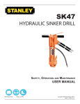
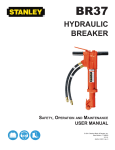
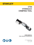
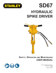
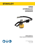
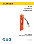
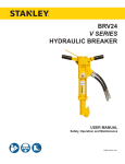
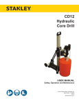
SK47
HYDRAULIC
SINKER DRILL
USER MANUAL
Safety, Operation and Maintenance
© 2014 Stanley Black & Decker, Inc.
New Britain, CT 06053
U.S.A.
10323 10/2014 Ver. 7
TABLE OF CONTENTS
SAFETY SYMBOLS...................................................................................................................................................4
SAFETY PRECAUTIONS...........................................................................................................................................5
TOOL STICKERS & TAGS.........................................................................................................................................6
HOSE TYPES.............................................................................................................................................................7
HOSE RECOMMENDATIONS...................................................................................................................................8
FIGURE 1. TYPICAL HOSE CONNECTIONS........................................................................................................8
HTMA REQUIREMENTS............................................................................................................................................9
OPERATION.............................................................................................................................................................10
TOOL PROTECTION & CARE.................................................................................................................................12
CHARGING THE ACCUMULATOR..........................................................................................................................13
FIGURE 2. CHARGING THE ACCUMULATOR....................................................................................................14
TROUBLESHOOTING.............................................................................................................................................15
SPECIFICATIONS....................................................................................................................................................16
ACCESSORIES.......................................................................................................................................................16
SK47 PARTS ILLUSTRATION.................................................................................................................................17
SK47 PARTS LIST...................................................................................................................................................18
IMPORTANT
To fill out a Product Warranty Validation form, and for information on your warranty,
visit Stanleyhydraulics.com and select the Company tab, Warranty.
(NOTE: The warranty Validation record must be submitted to validate the warranty).
SERVICING: This manual contains safety, operation, and routine maintenance instructions. Stanley Hydraulic
Tools recommends that servicing of hydraulic tools, other than routine maintenance, must be performed by an authorized and certified dealer. Please read the following warning.
WARNING
SERIOUS INJURY OR DEATH COULD RESULT FROM THE IMPROPER REPAIR OR
SERVICE OF THIS TOOL.
REPAIRS AND / OR SERVICE TO THIS TOOL MUST ONLY BE DONE BY AN
AUTHORIZED AND CERTIFIED DEALER.
For the nearest authorized and certified dealer, call Stanley Hydraulic Tools at the number listed on the back of this
manual and ask for a Customer Service Representative.
SK47 User Manual ◄ 3
SAFETY SYMBOLS
Safety symbols and signal words, as shown below, are used to emphasize all operator, maintenance and repair actions which, if not strictly followed, could result in a life-threatening situation, bodily injury or damage to equipment.
This is the safety alert symbol. It is used to alert you to potential personal injury
hazards. Obey all safety messages that follow this symbol to avoid possible
injury or death.
DANGER
This safety alert and signal word indicate an imminently hazardous situation
which, if not avoided, will result in death or serious injury.
WARNING
This safety alert and signal word indicate a potentially hazardous situation
which, if not avoided, could result in death or serious injury.
CAUTION
This safety alert and signal word indicate a potentially hazardous situation
which, if not avoided, could result in death or serious injury.
CAUTION
This signal word indicates a potentially hazardous situation which, if not avoided, may result in property damage.
NOTICE
This signal word indicates a situation which, if not avoided, will result in damage
to the equipment.
IMPORTANT
This signal word indicates a situation which, if not avoided, may result in damage to the equipment.
Always observe safety symbols. They are included for your safety and for the protection of the tool.
LOCAL SAFETY REGULATIONS
Enter any local safety regulations here. Keep these instructions in an area accessible to the operator and maintenance personnel.
4 ► SK47 User Manual
SAFETY PRECAUTIONS
Tool operators and maintenance personnel must always
comply with the safety precautions given in this manual
and on the stickers and tags attached to the tool and
hose.
•
Do not operate a damaged, improperly adjusted, or
incompletely assembled tool.
•
These safety precautions are given for your safety. Review them carefully before operating the tool and before
performing general maintenance or repairs.
Do not weld, cut with an acetylene torch, or hardface the tool bit.
•
To avoid personal injury or equipment damage, all
tool repair, maintenance and service must only be
performed by authorized and properly trained personnel.
•
Do not exceed the rated limits of the tool or use the
tool for applications beyond its design capacity.
•
Always keep critical tool markings, such as labels
and warning stickers legible.
•
Always replace parts with replacement parts recommended by Stanley Hydraulic Tools.
•
Check fastener tightness often and before each use
daily.
•
Never operate the tool if you cannot be sure that
underground utilities are not present.
•
Do not wear loose fitting clothing when operating the
tool.
•
Warning: Use of this tool on certain materials during
demolition could generate dust potentially containing a variety of hazardous substances such as asbestos, silica or lead. Inhalation of dust containing
these or other hazardous substances could result
in serious injury, cancer or death. Protect yourself
and those around you. Research and understand
the materials you are cutting. Follow correct safety
procedures and comply with all applicable national,
state or provisional health and safety regulations
relating to them, including, if appropriate arranging
for the safe disposal of the materials by a qualified
person.
The SK47 Hydraulic Sinker Drill will provide safe and
dependable service if operated in accordance with the
instructions given in this manual. Read and understand
this manual and any stickers and tags attached to the
tool and hoses before operation. Failure to do so could
result in personal injury or equipment damage.
•
Operator must start in a work area without bystanders. The operator must be familiar with all prohibited
work areas such as excessive slopes and dangerous terrain conditions.
•
Establish a training program for all operators to ensure safe operation.
•
Do not operate the tool unless thoroughly trained or
under the supervision of an instructor.
•
Always wear safety equipment such as goggles, ear,
head and breathing protection, and safety shoes at
all times when operating the tool.
•
Do not inspect or clean the tool while the hydraulic
power source is connected. Accidental engagement
of the tool can cause serious injury.
•
Supply hoses must have a minimum working pressure rating of 2500 psi/175 bar.
•
The hydraulic circuit control valve must be in the
OFF position when coupling or uncoupling the tool.
Wipe all couplers clean before connecting. Use only
lint-free cloths. Failure to do so may result in damage to the quick couplers and cause overheating of
the hydraulic system.
•
Do not operate the tool at oil temperatures above
140 °F/60 °C. Operation at higher oil temperatures
can cause operator discomfort and may damage the
tool.
SK47 User Manual ◄ 5
TOOL STICKERS & TAGS
SK47 SINKER DRILL
FLOW: 7-9 GPM/26-34 LPM
PRESS: 1500-2000 PSI
ACCUMULATOR CHARGE:
600 PSI NITROGEN
Stanley Hydraulic Tools
Division of The Stanley Works
3810 SE Naef Road
Milwaukie, Oregon 97267 USA
08103
SK47 Name Tag
NOTE:
THE INFORMATION LISTED
ON THE STICKERS SHOWN,
MUST BE LEGIBLE AT ALL
TIMES.
REPLACE DECALS IF
THEY BECOME WORN OR
DAMAGED. REPLACEMENTS
ARE AVAILABLE FROM
YOUR LOCAL STANLEY
DISTRIBUTOR.
The safety tag (P/N 15875) at right is
attached to the tool when shipped from
the factory. Read and understand the
safety instructions listed on this tag before
removal. We suggest you retain this tag and
attach it to the tool when not in use.
D A N G E R
1.
FAILURE TO USE HYDRAULIC HOSE LABELED AND CERTIFIED AS NON-CONDUCTIVE WHEN USING HYDRAULIC
TOOLS ON OR NEAR ELECTRICAL LINES MAY RESULT IN
DEATH OR SERIOUS INJURY.
BEFORE USING HOSE LABELED AND CERTIFIED AS NONCONDUCTIVE ON OR NEAR ELECTRIC LINES BE SURE THE
HOSE IS MAINTAINED AS NON-CONDUCTIVE. THE HOSE
SHOULD BE REGULARLY TESTED FOR ELECTRIC CURRENT LEAKAGE IN ACCORDANCE WITH YOUR SAFETY
DEPARTMENT INSTRUCTIONS.
2.
A HYDRAULIC LEAK OR BURST MAY CAUSE OIL INJECTION INTO THE BODY OR CAUSE OTHER SEVERE
PERSONAL INJURY.
A.
DO NOT EXCEED SPECIFIED FLOW AND PRESSURE
FOR THIS TOOL. EXCESS FLOW OR PRESSURE MAY
CAUSE A LEAK OR BURST.
B.
DO NOT EXCEED RATED WORKING PRESSURE OF
HYDRAULIC HOSE USED WITH THIS TOOL. EXCESS
PRESSURE MAY CAUSE A LEAK OR BURST.
C. CHECK TOOL HOSE COUPLERS AND CONNECTORS
DAILY FOR LEAKS. DO NOT FEEL FOR LEAKS WITH
YOUR HANDS. CONTACT WITH A LEAK MAY RESULT
IN SEVERE PERSONAL INJURY.
D A N G E R
D. DO NOT LIFT OR CARRY TOOL BY THE HOSES. DO
NOT ABUSE HOSE. DO NOT USE KINKED, TORN OR
DAMAGED HOSE.
3.
MAKE SURE HYDRAULIC HOSES ARE PROPERLY CONNECTED TO THE TOOL BEFORE PRESSURING SYSTEM.
SYSTEM PRESSURE HOSE MUST ALWAYS BE CONNECTED TO TOOL “IN” PORT. SYSTEM RETURN HOSE
MUST ALWAYS BE CONNECTED TO TOOL “OUT” PORT.
REVERSING CONNECTIONS MAY CAUSE REVERSE
TOOL OPERATION WHICH CAN RESULT IN SEVERE
PERSONAL INJURY.
4.
DO NOT CONNECT OPEN-CENTER TOOLS TO CLOSEDCENTER HYDRAULIC SYSTEMS. THIS MAY RESULT IN
LOSS OF OTHER HYDRAULIC FUNCTIONS POWERED BY
THE SAME SYSTEM AND/OR SEVERE PERSONAL INJURY.
5.
BYSTANDERS MAY BE INJURED IN YOUR WORK AREA.
KEEP BYSTANDERS CLEAR OF YOUR WORK AREA.
6.
WEAR HEARING, EYE, FOOT, HAND AND HEAD PROTECTION.
7.
TO AVOID PERSONAL INJURY OR EQUIPMENT DAMAGE,
ALL TOOL REPAIR MAINTENANCE AND SERVICE MUST
ONLY BE PERFORMED BY AUTHORIZED AND PROPERLY
TRAINED PERSONNEL.
I M P O R T A N T
I M P O R T A N T
READ OPERATION MANUAL AND
SAFETY INSTRUCTIONS FOR THIS
TOOL BEFORE USING IT.
READ OPERATION MANUAL AND
SAFETY INSTRUCTIONS FOR THIS
TOOL BEFORE USING IT.
USE ONLY PARTS AND REPAIR
PROCEDURES APPROVED BY
STANLEY AND DESCRIBED IN THE
OPERATION MANUAL.
USE ONLY PARTS AND REPAIR
PROCEDURES APPROVED BY
STANLEY AND DESCRIBED IN THE
OPERATION MANUAL.
TAG TO BE REMOVED ONLY BY
TOOL OPERATOR.
TAG TO BE REMOVED ONLY BY
TOOL OPERATOR.
SEE OTHER SIDE
SEE OTHER SIDE
SAFETY TAG P/N 15875 (Shown smaller then actual size)
6 ► SK47 User Manual
HOSE TYPES
The rated working pressure of the hydraulic hose must be equal to or higher than the relief valve setting on the hydraulic system. There are three types of hydraulic hose that meet this requirement and are authorized for use with
Stanley Hydraulic Tools. They are:
Certified non-conductive — constructed of thermoplastic or synthetic rubber inner tube, synthetic fiber braid
reinforcement, and weather resistant thermoplastic or synthetic rubber cover. Hose labeled certified nonconductive is the only hose authorized for use near electrical conductors.
Wire-braided (conductive) — constructed of synthetic rubber inner tube, single or double wire braid reinforcement, and weather resistant synthetic rubber cover. This hose is conductive and must never be used near
electrical conductors.
Fabric-braided (not certified or labeled non-conductive) — constructed of thermoplastic or synthetic rubber inner tube, synthetic fiber braid reinforcement, and weather resistant thermoplastic or synthetic rubber cover. This
hose is not certified non-conductive and must never be used near electrical conductors.
HOSE SAFETY TAGS
To help ensure your safety, the following DANGER tags are attached to all hose purchased from Stanley Hydraulic
Tools. DO NOT REMOVE THESE TAGS.
If the information on a tag is illegible because of wear or damage, replace the tag immediately. A new tag may be
obtained from your Stanley Distributor.
D A N G E R
D A N G E R
1.
FAILURE TO USE HYDRAULIC HOSE LABELED AND CERTIFIED AS NON-CONDUCTIVE
WHEN USING HYDRAULIC TOOLS ON OR NEAR ELECTRIC LINES MAY RESULT IN
DEATH OR SERIOUS INJURY.
FOR PROPER AND SAFE OPERATION MAKE SURE THAT YOU HAVE BEEN PROPERLY TRAINED IN CORRECT PROCEDURES REQUIRED FOR WORK ON OR AROUND
ELECTRIC LINES.
2.
BEFORE USING HYDRAULIC HOSE LABELED AND CERTIFIED AS NON-CONDUCTIVE
ON OR NEAR ELECTRIC LINES. WIPE THE ENTIRE LENGTH OF THE HOSE AND FITTING WITH A CLEAN DRY ABSORBENT CLOTH TO REMOVE DIRT AND MOISTURE AND
TEST HOSE FOR MAXIMUM ALLOWABLE CURRENT LEAKAGE IN ACCORDANCE WITH
SAFETY DEPARTMENT INSTRUCTIONS.
3.
DO NOT EXCEED HOSE WORKING PRESSURE OR ABUSE HOSE. IMPROPER USE
OR HANDLING OF HOSE COULD RESULT IN BURST OR OTHER HOSE FAILURE.
KEEP HOSE AS FAR AWAY AS POSSIBLE FROM BODY AND DO NOT PERMIT DIRECT
CONTACT DURING USE. CONTACT AT THE BURST CAN CAUSE BODILY INJECTION
AND SEVERE PERSONAL INJURY.
4.
HANDLE AND ROUTE HOSE CAREFULLY TO AVOID KINKING, ABRASION, CUTTING, OR
CONTACT WITH HIGH TEMPERATURE SURFACES. DO NOT USE IF KINKED. DO NOT
USE HOSE TO PULL OR LIFT TOOLS, POWER UNITS, ETC.
5.
CHECK ENTIRE HOSE FOR CUTS CRACKS LEAKS ABRASIONS, BULGES, OR DAMAGE TO COUPLINGS IF ANY OF THESE CONDITIONS EXIST, REPLACE THE HOSE
IMMEDIATELY. NEVER USE TAPE OR ANY DEVICE TO ATTEMPT TO MEND THE HOSE.
6.
AFTER EACH USE STORE IN A CLEAN DRY AREA.
SEE OTHER SIDE
SIDE 1
SEE OTHER SIDE
(Shown smaller than actual size)
DO NOT REMOVE THIS TAG
DO NOT REMOVE THIS TAG
THE TAG SHOWN BELOW IS ATTACHED TO “CERTIFIED NON-CONDUCTIVE” HOSE
SIDE 2
D A N G E R
D A N G E R
1.
DO NOT USE THIS HYDRAULIC HOSE ON OR NEAR ELECTRIC LINES. THIS HOSE IS
NOT LABELED OR CERTIFIED AS NON-CONDUCTIVE. USING THIS HOSE ON OR NEAR
ELECTRICAL LINES MAY RESULT IN DEATH OR SERIOUS INJURY.
5.
CHECK ENTIRE HOSE FOR CUTS CRACKS LEAKS ABRASIONS, BULGES, OR DAMAGE TO
COUPLINGS IF ANY OF THESE CONDITIONS EXIST, REPLACE THE HOSE IMMEDIATELY.
NEVER USE TAPE OR ANY DEVICE TO ATTEMPT TO MEND THE HOSE.
2.
FOR PROPER AND SAFE OPERATION MAKE SURE THAT YOU HAVE BEEN PROPERLY
TRAINED IN CORRECT PROCEDURES REQUIRED FOR WORK ON OR AROUND ELECTRIC LINES.
6.
AFTER EACH USE STORE IN A CLEAN DRY AREA.
3.
DO NOT EXCEED HOSE WORKING PRESSURE OR ABUSE HOSE. IMPROPER USE OR
HANDLING OF HOSE COULD RESULT IN BURST OR OTHER HOSE FAILURE. KEEP HOSE
AS FAR AWAY AS POSSIBLE FROM BODY AND DO NOT PERMIT DIRECT CONTACT
DURING USE. CONTACT AT THE BURST CAN CAUSE BODILY INJECTION AND SEVERE
PERSONAL INJURY.
4.
HANDLE AND ROUTE HOSE CAREFULLY TO AVOID KINKING, CUTTING, OR CONTACT
WITH HIGH TEMPERATURE SURFACES. DO NOT USE IF KINKED. DO NOT USE HOSE TO
PULL OR LIFT TOOLS, POWER UNITS, ETC.
DO NOT REMOVE THIS TAG
DO NOT REMOVE THIS TAG
THE TAG SHOWN BELOW IS ATTACHED TO “CONDUCTIVE” HOSE.
SEE OTHER SIDE
SEE OTHER SIDE
SIDE 1
SIDE 2
(Shown smaller than actual size)
SK47 User Manual ◄ 7
8 ► SK47 User Manual
All hydraulic hose must meet or exceed
specifications as set forth by SAE J517.
All hydraulic hose must have at least a rated
minimum working pressure equal to the maximum hydraulic system relief valve setting.
This chart is intended to be used for hydraulic
tool applications only based on Stanley Hydraulic Tools tool operating requirements and
should not be used for any other applications.
The chart to the right shows recommended
minimum hose diameters for various hose
lengths based on gallons per minute (gpm)/
liters per minute (lpm). These recommendations are intended to keep return line pressure
(back pressure) to a minimum acceptable level to ensure maximum tool performance.
Tool to Hydraulic Circuit Hose
Recommendations
15-34
MM
Inside Diameter
INCH
USE
(Press/Return)
PSI
up to 10
up to 3
3/8
10
Both
2250
49-60
13-16
FLOW >>>
RETURN
<<< FLOW
PRESSURE
26-100
up to 25
100-200
51-100
up to 50
100-300
51-100
up to 50
26-100
up to 25
8-30
up to 8
30-60
15-30
up to 15
30-90
15-30
up to 15
7.5-30
up to 7.5
Figure 1. Typical Hose Connections
49-60
38-49
10-13
13-16
19-40
5-10.5
38-49
19-40
5-10.5
10-13
19-40
5-10.5
38-49
15-23
10-13
15-23
4-6
19
25.4
16
19
19
25.4
5/8
3/4
3/4
1
19
3/4
1
16
3/4
16
19
3/4
5/8
16
5/8
5/8
16
13
13
10
5/8
1/2
1/2
3/8
Return
Pressure
Return
Pressure
Return
Pressure
Return
Pressure
Both
Return
Pressure
Both
Both
Both
Both
2500
2500
2500
2500
2500
2500
2500
2500
2500
2500
2500
2500
2500
2500
2500
175
175
175
175
175
175
175
175
175
175
175
175
175
175
175
155
BAR
Min. Working Pressure
Certified Non-Conductive Hose - Fiber Braid - for Utility Bucket Trucks
METERS
Hose Lengths
FEET
Conductive Hose - Wire Braid or Fiber Braid -DO NOT USE NEAR ELECTRICAL CONDUCTORS
4-6
4-9
LPM
Oil Flow
GPM
HOSE RECOMMENDATIONS
HTMA / EHTMA REQUIREMENTS
HTMA / EHTMA REQUIREMENTS
HTMA
HYDRAULIC SYSTEM REQUIREMENTS
TYPE I
Nominal Operating Pressure
(at the power supply outlet)
4-6 gpm
(15-23 lpm)
1500 psi
(103 bar)
TOOL TYPE
TYPE II
TYPE RR
7-9 gpm
(26-34 lpm)
1500 psi
(103 bar)
9-10.5 gpm
(34-40 lpm)
1500 psi
(103 bar)
System relief valve setting
(at the power supply outlet)
2100-2250 psi
(145-155 bar)
2100-2250 psi
(145-155 bar)
2200-2300 psi
(152-159 bar)
2100-2250 psi
(145-155 bar)
Maximum back pressure
(at tool end of the return hose)
250 psi
(17 bar)
250 psi
(17 bar)
250 psi
(17 bar)
250 psi
(17 bar)
Measured at a max. fluid viscosity of:
(at min. operating temperature)
400 ssu*
400 ssu*
400 ssu*
400 ssu*
(82 centistokes) (82 centistokes) (82 centistokes) (82 centistokes)
Temperature: Sufficient heat rejection
capacity to limit max. fluid temperature to:
(at max. expected ambient temperature)
140° F
(60° C)
Flow Range
140° F
(60° C)
140° F
(60° C)
TYPE III
11-13 gpm
(42-49 lpm)
1500 psi
(103 bar)
140° F
(60° C)
3 hp
5 hp
6 hp
7 hp
Min. cooling capacity at a temperature
(2.24 kW)
(3.73 kW)
(5.22 kW)
(4.47 kW)
difference of between ambient and fluid
40° F
40° F
40° F
40° F
temps
(22° C)
(22° C)
(22° C)
(22° C)
NOTE:
Do not operate the tool at oil temperatures above 140° F (60° C). Operation at higher temperatures can cause operator
discomfort at the tool.
Filter
Min. full-flow filtration
Sized for flow of at least:
(For cold temp. startup and max.
dirt-holding capacity)
25 microns
30 gpm
(114 lpm)
Hydraulic fluid Petroleum based
(premium grade, anti-wear, non-conductive)
Viscosity (at min. and max. operating temps)
100-400 ssu*
25 microns
30 gpm
(114 lpm)
25 microns
30 gpm
(114 lpm)
100-400 ssu*
100-400 ssu*
(20-82 centistokes)
25 microns
30 gpm
(114 lpm)
100-400 ssu*
NOTE:
When choosing hydraulic fluid, the expected oil temperature extremes that will be experienced in service determine the
most suitable temperature viscosity characteristics. Hydraulic fluids with a viscosity index over 140 will meet the requirements
over a wide range of operating temperatures.
*SSU = Saybolt Seconds Universal
EHTMA
HYDRAULIC SYSTEM
REQUIREMENTS
CLASSIFICATION
B
C
D
Nominal Operating Pressure
(at the power supply outlet)
3.5-4.3 gpm
(13.5-16.5 lpm)
1870 psi
(129 bar)
4.7-5.8 gpm
(18-22 lpm)
1500 psi
(103 bar)
7.1-8.7 gpm
(27-33 lpm)
1500 psi
(103 bar)
9.5-11.6 gpm
(36-44 lpm)
1500 psi
(103 bar)
11.8-14.5 gpm
(45-55 lpm)
1500 psi
(103 bar)
System relief valve setting
(at the power supply outlet)
2495 psi
(172 bar)
2000 psi
(138 bar)
2000 psi
(138 bar)
2000 psi
(138 bar)
2000 psi
(138 bar)
Flow Range
NOTE: These are general hydraulic system requirements. See tool specification page for tool specific requirements
SK47 User Manual ◄ 9
OPERATION
The recommended hose size is .500 inch/12 mm ID up
to 50 ft/15 m long and .625 inch/16 mm ID minimum up
to 100 ft/30 m.
PRE-OPERATION PROCEDURES
CHECK POWER SOURCE
1. Using a calibrated flowmeter and pressure gauge,
check that the hydraulic power source develops a
flow of 7–9 gpm/26–34 lpm at 1500–2000 psi/105–
140 bar.
2. Make certain the hydraulic power source is equipped
with a relief valve set to open at 2100–2250 psi/145–
155 bar maximum.
INSTALL DRILL STEEL & ROCK BIT
Use standard 4-1/4 inch shank × 7/8 inch hex drill steels.
Drill steels are available in a variety of lengths. Start
with a short length so that the tool may be operated at a
normal standing position. The tool handles should never
exceed chest height during operation.
1. Thread a rock bit onto the drill steel.
2. Rotate the latch out and up.
3. Slide the drill steel into the tool.
4. Rotate the latch down being careful not to pinch your
fingers. When correctly installed, the collar on the
drill steel should be above the bottom of the latch.
CONNECT HOSES
1. Wipe all hose couplers with a clean, lint-free cloth
before making connections.
2. Connect the hoses from the hydraulic power source
to the tool fittings or quick disconnects. It is a good
practice to connect return hoses first and disconnect them last to minimize or avoid trapped pressure
within the tool.
3. Observe flow indicators stamped on hose couplers
to ensure that fluid flow is in the proper direction.
The female coupler on the tool hose is the inlet coupler.
4. Move the hydraulic circuit control valve to the ON
position to operate the tool.
NOTE:
If uncoupled hoses are left in the sun, pressure increase within the hoses may make them difficult to
connect. When possible, connect the free ends of
the hoses together.
5. Connect the hose from the air supply to the hose on
the tool.
10 ► SK47 User Manual
NOTICE
The air supply must be minimum 30 cfm at 120 psi.
Supplying less than these specifications may result
in inadequate extraction of rock cuttings; cause
cuttings to migrate up the drill steel and into the tool
and result in tool damage; diminish drilling time; and
cause premature wear of the drill bit.
OPERATION PROCEDURES
1. Observe all safety precautions.
2. Install the appropriate tool bit for the job.
3. Start the hydraulic supply and turn the circuit control
valve to the ON position.
4. Open the air valve on the tool just enough to permit
a small amount of air flow from the tool bit.
NOTE:
Air flow must be continuous during drilling to avoid
clogging of the air passages and/or back-flushing of
waste products into the drill.
5. Place the bit firmly on the surface to be drilled. Do
not operate the sinker drill without the drill steel in
contact with the work surface. Adequate down pressure is very important.
6. Several methods can be used to reduce the tendency for the drill to “walk” on the surface to be drilled
before the hole is initiated.
If the trigger is partially depressed, the piston will
cycle at low speed, without tool bit rotation, allowing
a start hole to be made. This will keep the drill in
place when full power is applied.
Rotating the motor control lever straight up will shut
off all rotation allowing the operator to establish a
starting hole prior to full application.
7. The rotation control lever controls rotation speed
from 0 to approximately 300 rpm. Normal drilling is
best accomplished with the lever halfway between
fully on and straight up off position.
NOTE:
Normal drill rotation is counterclockwise when
viewed from the top of the tool. The clockwise rotation position of the motor control lever has been
blocked with a roll pin stop to avoid unscrewing a
drill bit at the bottom of the drilled hole.
OPERATION
8. Ensure the rock bit is rotating at a moderate speed
(not too fast, not too slow). When starting the hole,
it is best to start at a slow impact and rotation speed
until the rock bit has carved out a depression in the
material being drilled. If the rock bit is not rotating
open the hydraulic valve lever further. If the rock bit
still does not rotate adjust the motor control knob
until rotation is achieved.
9. After the rock bit has carved out a depression in the
material being drilled, open the hydraulic valve lever fully. Readjust the motor control knob to obtain
a good drilling speed. Adjust the air valve to ensure
the cuttings are being extracted from the drill hole.
COLD WEATHER OPERATION
If the breaker is to be used during cold weather, preheat
the hydraulic fluid at low engine speed. When using the
normally recommended fluid, fluid temperature should
be at or above 50 °F/10 °C (400 ssu/82 centistokes) before use.
Damage to the hydraulic system or breaker can result
from use with fluid that is too viscous or thick.
FLUSHING REQUIREMENTS
•
The SK47 is designed for air flushing only.
•
The minimum of CFM/7 liters per second at 75 psi/5
bar of compressed air should be used for flushing
the chips out of the drilled hole.
•
The minimum recommended hose size is 3/8inch/10 mm ID and must have a minimum working
pressure rating of 150 psi/10 bar or 150 percent of
the maximum pressure produced by the system,
whichever is higher.
•
Air hoses must have an oil-resistant inner surface
and an abrasion-resistant exterior surface. When
severe operating conditions make the possibility of
cutting or damaging the hose likely, the hose shall
be of extra-ply armored, or other protective construction.
•
Pressure regulators shall be used to limit maximum
air pressure at the tool to 100 psi/7 bar.
•
An accessible means for shutting off the air supply
to the sinker drill should be provided.
•
Automatic filtering systems are recommended.
10. Keep the drill steel centered in the hole.
11. Insufficient air flow can cause the drill steel to bind
in the hole.
12. Apply adequate feed pressure to the sinker drill to
maintain optimum drilling performance.
13. When drilling deep holes, it is advantageous to stop
drilling every 1 to 2 minutes. This allows the receiver
and hoses to charge and provide a short burst of air
when the tool is again turned on to clear excess cutting from the hole.
14. When the bottom of the tool comes within 6 inches
of the drill hole, it is time to either add another section of drill steel or replace the existing drill steel with
a longer section. Close the hydraulic valve lever but
leave the air valve ON and then lift the tool with drill
steel and rock bit out of the hole. Leaving the air
valve ON helps prevent cuttings from falling around
the bit while the bit is lifted from the hole.
15. When the tool, drill steel and bit have been removed
from the drill hole, turn the valve lever OFF and turn
the hydraulic supply circuit control valve OFF before
changing the drill steel or rock bit.
SK47 User Manual ◄ 11
TOOL PROTECTION & CARE
NOTICE
In addition to the Safety Precautions found in
this manual, observe the following for equipment
protection and care.
•
Make sure all couplers are wiped clean before connection.
•
The hydraulic circuit control valve must be in the
OFF position when coupling or uncoupling hydraulic
tools. Failure to do so may result in damage to the
quick couples and cause overheating of the hydraulic system.
•
Keep tool bit sharp for maximum drilling performance. Make sure that tool bits are not chipped or
rounded on the striking end.
•
Never operate a hammer drill without a tool bit or
without holding it against the work surface.
•
Tool repair should be performed by experienced
personnel only.
•
Always store the tool in a clean dry space, safe from
damage or pilferage.
•
•
Make sure the circuit PRESSURE hose (with male
quick disconnect) is connected to the IN port. The
circuit RETURN hose (with female quick disconnect)
is connected to the opposite port. Do not reverse circuit flow. This can cause damage to internal seals.
Make certain that the recommended relief valves
are installed in the pressure side of the system.
•
Do not use the tool for applications for which it was
not intended.
•
Always replace hoses, couplings and other parts
with replacement parts recommended by Stanley
Hydraulic Tools. Supply hoses must have a minimum working pressure rating of 2500 psi/172 bar.
•
Do not exceed the rated flow and pressure. See
Specifications in this manual for correct flow rate
and pressure rating. Rapid failure of the internal
seals may result.
•
Always keep critical tool markings, such as warning
stickers and tags legible.
12 ► SK47 User Manual
CHARGING THE ACCUMULATOR
ACCUMULATOR TESTING
PROCEDURE
To check or charge the accumulator the following equipment is required:
31254 Charge Kit: which includes the following (see Figure 2).
•
Accumulator Tester (Part Number 02835).
•
Charging Assembly (P/N 15304) Includes a liquid
filled gauge w/snub valve, hose and charge fitting.
•
NITROGEN bottle with a 800 psi/56 bar minimum
charge (NOT included in 31254 Charge Kit.)
1. Remove the valve cap assembly from the sinker drill
(see Figure 2 for location).
2. Remove the protective cap and loosen the 5/8-inch
hex locking nut on the tool charging valve 1-1/2
turns.
3. Holding the chuck end of Accumulator Tester (P/N
02835) turn the gauge fully counterclockwise to ensure that the stem inside the chuck is completely
retracted.
4. Thread the tester onto the accumulator charging valve. Do not advance the gauge-end into the
chuck-end. Turn as a unit. Seat the chuck on the
accumulator charging valve and hand tighten only.
5. Advance the valve stem of the tester by turning the
gauge-end clockwise until a pressure is read on the
gauge (charge pressure should be 600–700 psi/42–
48 bar).
ACCUMULATOR CHARGING
1. Perform Steps 1 through 4 of the accumulator testing procedure above.
2. Connect the chuck of the charging assembly to the
charging valve on the accumulator tester or, if preferred, remove the tester from the charging valve
and connect the charging assembly chuck directly
to the charging valve.
3. Adjust the regulator to the charging pressure of 600
psi/42 bar.
NOTE:
It may be necessary to set the gauge at 650-700
psi/45-48 bar to overcome any pressure drop
through the charging system.
4. Open the valve on the charging assembly hose.
5. When the accumulator is fully charged close the
valve on the charging assembly hose and remove
the charging assembly chuck from the accumulator
tester or tool charging valve.
6. If the accumulator tester has been used, be sure to
turn the gauge-end fully counterclockwise before removing the tester from the charging valve of the tool.
7. Tighten the 5/8-inch hex locking nut on the tool
charging valve and replace the protective cap.
8. Replace the valve cap assembly.
6. If pressure is OK, unscrew the gauge-end from the
chuck to retract the stem, then unscrew the entire
tester assembly from the accumulator charging
valve. If pressure is low, charge the accumulator as
described in the following paragraph.
7. Tighten the 5/8-inch hex locking nut on the tool
charging valve. Be careful not to overtighten. Install
the protective cap and valve cap assembly.
SK47 User Manual ◄ 13
CHARGING THE ACCUMULATOR
Figure 2. Charging the Accumulator
14 ► SK47 User Manual
TROUBLESHOOTING
PROBLEM
Tool does not run.
CAUSE
SOLUTION
Power unit not functioning.
Check power unit for proper flow and pressure
(7–9 gpm/26–34 lpm, 1500–2000 psi/105–140
bar.
Couplers or hoses blocked.
Remove restriction.
Pressure and return line hoses
reversed at ports.
Be sure hoses are connected to their proper
ports.
Mechanical failure of piston or
automatic valve.
Disassemble breaker and inspect for damaged
parts.
Power unit not functioning.
Check power unit for proper flow and pressure
(7–9 gpm/26–34 lpm, 1500–2000 psi/105–140
bar.
Couplers or hoses blocked.
Remove restriction.
Low accumulator charge (pressure
hose will pulse more than normal).
Recharge accumulator. Replace diaphragm if
charge loss continues.
Fluid too hot (above 140 °F/60 °C).
Provide cooler to maintain proper fluid
temperature (130 °F/55 °C).
Insufficient air or water
15–25 cfm/7–12 liters per second minimum
required.
Low gpm supply from power unit.
Check power unit for proper flow (7–9 gpm/26–
34 lpm).
High back-pressure.
Check hydraulic system for excessive backpressure (over 250 psi/17 bar).
Couplers or hoses blocked.
Remove restriction.
Orifice plug blocked.
Remove restriction.
Fluid too hot (above 140 °F/60 °C) or
too cold (below 60 °F/16 °C).
Check power unit for proper fluid temperature.
Bypass cooler to warm the fluid or provide cooler
to maintain proper temperature.
Relief valve set too low.
Adjust relief valve to 2100–2250 psi/145–155
bar.
Tool gets hot.
Hot fluid going through tool.
Check power unit. Be sure flow rate is not too
high causing part of the fluid to go through the
relief valve. Provide cooler to maintain proper
fluid temperature (140°F/60°C max). Check the
relief valve setting.
Fluid leakage on drill steel.
Lower piston or drive hex seal failure. Replace seals.
Fluid leakage through charge
valve cap.
Upper piston seal failure or
accumulator O-ring failure or
accumulator charge loss or failure.
Replace seals, recharge or replace accumulator
diaphragm.
Fluid leakage around trigger.
Valve spool seal failure.
Replace seals.
Low rotation torque.
Motor not completely broken in.
Continue operation to break in motor.
Excessive oil temperature causes
operating pressure loss.
Provide cooler to maintain oil temperature
(under 140 °F).
Damage to motor clearances.
Repair as required.
Insufficient air or water.
15–25 cfm/7–12 liters per second minimum
required.
Mechanical binding during drilling.
Take care to guide drill straight.
Tool does not drill effectively.
Tool operates slow.
SK47 User Manual ◄ 15
SPECIFICATIONS
Shank Size....................................................................................................4-1/4 in. × 7/8 in. Hex/108 mm × 22 mm
Pressure Range................................................................................................................1500-2000 psi/105-140 bar
Flow Range....................................................................................................................................7-9 gpm/26-34 lpm
Optimum Flow........................................................................................................................................ 9 gpm/34 lpm
Maximum Back Pressure......................................................................................................................250 Psi/17 bar
Connect Size & Type........................................................................................................ 3/8 in. Male Pipe Hose End
Weight.......................................................................................................................................................52 lbs/24 kg
Length...................................................................................................................................................... 23 in./58 cm
Width........................................................................................................................................................ 14 in./35 cm
Hose Whips.................................................................................................................................................... Included
Port Size.................................................................................................................................................-8 SAE O-ring
ACCESSORIES
Drill Steels for use with Air
7/8 in./22 mm Hex × 4-1/4 in./108 mm H Thread, 24 in./61 cm UC....................................................................05174
Carbide Rock Bits for use with Air
1-3/8 in./34.9 mm Diameter H Thread................................................................................................................05177
1-1/2 in./38.1 mm Diameter H Thread................................................................................................................05178
2 in./50.8 mm Diameter H Thread......................................................................................................................04914
UC denotes dimension measured from bottom tip of tool to bottom surface of collar.
Test Equipment
Accumulator Charge Assembly (incl. Liquid Filled Gauge w/ Valve, Hose, & Charge Fitting)............................ 15304
Accumulator Tester.............................................................................................................................................02835
Flow and Pressure Tester...................................................................................................................................04182
Accumulator Charge Kit (Includes 02835 tester, 15304 charge assy and 372047 charge kit box).................... 31254
16 ► SK47 User Manual
SK47 PARTS ILLUSTRATION
SK47 User Manual ◄ 17
SK47 PARTS LIST
ITEM
PART
NO.
QTY DESCRIPTION
ITEM
PART
NO.
QTY DESCRIPTION
1
07975
1
HANDLE ASSEMBLY (INCL ITEMS 2–5)
42
04938
1
WASHER
2
20499
1
CHARGE VALVE
43
04940
1
RETAINING RING
3
04371
1
TRIGGER
44
04939
1
LEVER
4
07483
1
HANDLE
45
01607
1
SETSCREW
5
07492
2
SPIROL PIN
46
01749
2
ROLL PIN
6
02494
2
HANDLE GRIP
47
11197
2
BACK-UP RING
7
04058
1
SPRING
48
00783
1
PIPE PLUG
8
04077
1
VALVE SPOOL – OPEN CENTER –
MODEL SK47130
49
02900
5
ROLL PIN
15188
1
VALVE SPOOL – OPEN, CONSTANT ON
– MODEL SK47131
50
08096
1
GASKET
51
08095
1
MOTOR CHAMBER
9
07699
1
BUSHING ASSY (INCL ITEMS 10–12)
52
03826
2
BEARING
10
04057
1
BUSHING
53
04033
1
IDLE GEAR
11
00293
1
O-RING
54
11196
2
QUAD RING
12
01362
1
O-RING
55
04949
1
THRUST BACK-UP WASHER
13
04056
1
ROD WIPER
56
04948
1
THRUST WASHER
14
07493
1
CHARGE VALVE CAP
57
08094
1
DRIVE HEX
15
08087
4
SIDE ROD
58
04787
1
KEY
16
04374
4
LOCK NUT
59
04947
2
BEARING
17
07479
1
ACCUMULATOR DIAPHRAGM
60
05975
1
DRIVE GEAR
18
11588
1
ACCUMULATOR VALVE BLOCK
61
00713
2
DOWEL PIN
19
04381
2
BACK-UP RING
62
08093
1
MOTOR PLATE
20
04379
2
O-RING
63
00682
2
CAPSCREW
21
08088
1
PORTING BLOCK
64
04756
2
LATCH WASHER
22
08089
1
AUTOMATIC VALVE BODY
65
07063
8
WAVE SPRING
23
04571
2
PUSH PIN
66
04759
1
BACK-UP SPRING
24
04382
1
AUTOMATIC VALVE
67
04761
1
RETAINING RING
25
04605
4
PUSH PIN
68
16445
1
LATCH
26
08091
1
PISTON
69
01652
2
HOSE ASSY
27
08090
1
FLOW SLEEVE
70
01257
1
O-RING
28
04383
1
FLOW SLEEVE TUBE
71
04801
1
HOSE ASSY
29
08099
1
TUBE SEAL
72
00769
1
CAPSCREW
30
08100
1
AIR TUBE ASSY
73
00114
1
ROLL PIN
31
08092
1
DRIVE MOTOR CONTROL BLOCK
ASSY
74
00018
2
O-RING
75
03972
1
FEMALE COUPLER
16446
1
DRIVE MOTOR CONTROL BLOCK
ASSY W/O DELAY VALVE
76
03973
1
MALE COUPLER
77
18643
4
SETSCREW
80
06343
1
PLASTIC CAP (US VERSION ONLY)
NOT SHOWN
81
06345
2
PLASTIC PLUG (US VERSION ONLY)
NOT SHOWN
82
08103
1
NAME TAG
32
08097
1
VALVE SPOOL
33
08098
1
SPRING
34
08104
1
O-RING PLUG
35
04934
1
CUP SEAL
36
04780
1
WASHER
37
04386
1
CUP SEAL
38
02022
1
O-RING
39
00473
1
O-RING
40
04937
1
MOTOR CONTROL VALVE
41
01211
3
O-RING
18 ► SK47 User Manual
09542
SEAL KIT
Stanley Hydraulic Tools
3810 SE Naef Road
Milwaukie, Oregon 97267-5698 USA
(503) 659-5660 / Fax (503) 652-1780
www.stanleyhydraulics.com