1
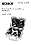
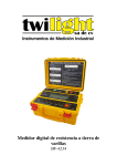
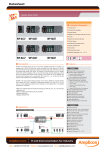
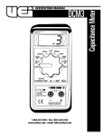
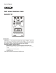
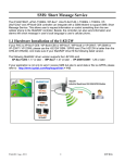
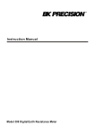
User Guide 4 wire Earth Resistance Tester Model GRT300 Introduction Congratulations on your purchase of Extech’s 4 Wire Earth Resistance Tester. The Model GRT300 has been designed and tested according to the IEC Publication 348, safety requirements for Electronic Measuring Apparatus, EN 61010-1, EN 61326-1, EN 61557-1 , EN 61557-5 and other safety standards. Proper use and care of this meter will provide many years of reliable service. Safety Notes Read the all safety information carefully before attempting to operate or service the meter. Use the meter only as specified in this manual. Otherwise, the protection provided by the meter may be impaired. Rated environmental conditions : Indoor & outdoor use. Installation Category IV 300V. Pollution Degree 2. Altitude up to 2000m. Relative Humidity 80% max. Ambient temperature 0-40°C. Observe the International Electrical Symbols listed below : Detector is protected throughout by double insulation or reinforced insulation. Warning ! Risk of electric shock. Caution ! Refer to this manual before using the detector. Earth(ground) terminal. Equipment complies with current EU directives. WARNING To avoid electrical shock, do not touch the terminals during tests Never apply Voltage higher than 300V across P1 and P2 terminals. 2 GRT300-EU-EN v1.1 08/13 Features Microprocessor controlled with advanced safety features Two line LCD display Auto-Ranging Earth resistance testing with four ranges: 0-2Ω/0-20Ω/0-200Ω/0-2kΩ Earth voltage measuring range of 0-300Vac Automatic C spike check. Automatic P spike check. 2-wire test 3-wire test 4-wire test Auto power off Data hold Safety standard: EN 61010-1 CATIV 300V, EN 61326-1 Meter Description 1. C1 terminal (Black test lead connection) 4 2. P1 terminal (Green test lead connection) 3 3. P2 terminal (Yellow test lead connection) 2 4. C2 terminal (Red test lead connection) 5 Display 6. Rc LED 7. Rp LED 8. 2 Wire button 9. 3 Wire button 1 5 6 7 10. 4 Wire button 11. ACV button 12. Power button 13. TEST/STOP button 8 9 10 11 12 13 3 GRT300-EU-EN v1.1 08/13 Operation Battery Voltage check 1. Press the "ON/OFF" button, if "Battery Low" appears on the display, replace the batteries. Earth Voltage measurement 1. Connect the test leads as shown below. E ES P1 C1 1 MAX. AC 300V S H P2 C2 2 (1) Earth electrode (rod) under test (2) Test spike 2. Press the "ON/OFF" button and wait for “Select Function” to appear on the display. 3. Press the "ACV" button and then the "TEST/STOP" button. 4. The earth voltage will be displayed on the display. Note: When the earth voltage is more than 10V, errors in earth resistance measurements may occur. Make sure that the indicated value is less than 10V. 4 GRT300-EU-EN v1.1 08/13 Earth Resistance measurement Note: The measured results may be influenced by inductive or capacitive coupling if the test leads are twisted or adjacent to each other. When connecting the Probes, keep the leads separated. Setup Insert the Potential spike and the Current spike (if required) as deep as possible into the soil. The distance between spikes must be 5 to 10 meters (16 to 32 feet). Four-terminal earth resistance measurements E ES S H C1 P1 P2 C2 1 2 MAX. AC 300V 3 (1) Earth electrode (rod) under test (2) Potential spike (3) Current spike Three-terminal earth resistance measurements E ES S H C1 P1 P2 C2 1 2 MAX. AC 300V 3 (1) Earth electrode (rod) under test (2) Potential spike (3) Current spike Two-terminal earth resistance measurements E ES P1 C1 1 MAX. AC 300V S H P2 C2 2 (1) Earth electrode (rod) under test (2) Potential spike 5 GRT300-EU-EN v1.1 08/13 Testing 1. Connect the test leads for 2, 3 or 4 terminal testing. 2. Press the ON/OFF button and wait for the “Select Function” screen to appear. 3. Press the "2P", "3P" or "4P" button that agrees with the setup. 4. Press "TEST/STOP" button to begin the test. 5. The meter will beep while the test is in progress (approximately 10 seconds) and then the reading will appear on the lower line of the display. Notes: "Rc" & "Rp" LED indications: Rc: No test current output. Check connections. Rp: If Rp is on and the display indicates “> 2 kΩ”, the earth resistance is greater than 2000Ω. If, in "4P" mode, the display shows "Vp Error", short circuit C1(black) and P1(green). Measurement Considerations 2 terminal testing of earth resistance is appropriate for most general purpose testing in normally conductive soil. But, 2 terminal measurements include test lead and contact resistance in the measurement and the result will be a reading slightly higher than the true earth resistance. When measured results are higher than desired or if measurement directives require multi-terminal techniques, switch to the 3 or 4 terminal techniques as needed. 6 GRT300-EU-EN v1.1 08/13 Maintenance 1. Rear cover 2. Battery 3. Fuse 1 2 3 Fuse Replacement 1. Disconnect the test leads from the instrument. 2. Remove the rear cover by removing two screws. 3. Remove and replace the fuse with the new one of the same value and size 0.1A/250V, 5 x 20mm. 4. Replace and secure the rear cover. Battery replacement When "Battery Low" appears on the display, replace the batteries. 1. Disconnect the test leads from the instrument and remove the rear cover and the batteries. 2. The tester's battery is situated under the tester. 3. Replace with eight 1.5V AA light batteries, taking care to observe correct polarity. 4. Reinstall battery holder and the battery cover. Cleaning And Storage WARNING: To avoid electrical shock or damage to the meter, do not get water inside the case. Periodically wipe the case with a damp cloth and detergent, do not use abrasives or solvents. 7 GRT300-EU-EN v1.1 08/13 Specifications Measuring Ranges Accuracy Earth Resistance Resolution Test Frequency Test Current Temperature & Humidity Earth Resistance: 0-2Ω, 0-20Ω, 0-200Ω, 0-2kΩ Earth Voltage: 0-300V AC (40 to 500Hz) Earth Resistance: ±(2%rdg+3dgt) Earth Voltage: ±(2%rdg+3dgt) 0-2Ω : 0.01Ω 0-20Ω : 0.1Ω 0-200Ω : 1Ω 0-2kΩ : 0.01kΩ 820Hz 2mA Operating : 0 to 50°C (32 to 122°F) أ80%R.H. Storage : -10 to 60°C (14 to 140°F) أ80%R.H. Power Source Dimensions Weight Fuse( 1.5V(AA) x 8 250(L) x 190(W) x 110(D)mm (9.84x7.5x4.33”) Approx. 1430g(battery included) 0.1A/250V 5 x 20mm 8 GRT300-EU-EN v1.1 08/13 Copyright © 2013 FLIR Systems, Inc. All rights reserved including the right of reproduction in whole or in part in any form ISO‐9001 Certified www.extech.com 9 GRT300-EU-EN v1.1 08/13