1
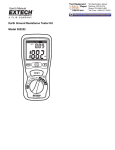
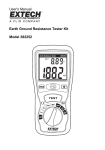
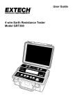
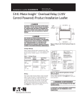
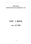
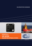
User's Manual
Earth Ground Resistance Tester
Model 382152
Introduction
Congratulations on your purchase of the Extech Earth Ground Resistance Tester. This
device can measure resistance (in 3 ranges) and AC voltage to 200V. 2mA constant
current test signal permits earth resistance tests without tripping current breakers in the
circuit under test. Single, momentary tests or automatic 3-minute tests can be selected.
This device was designed to meet IEC-1010 (EN 61010) safety standards.
Earth Ground Resistance Testers are useful for:
• Estimating ground resistance of a proposed substation or transmission tower.
• Computing inductive coupling between neighboring power and communication
circuits.
• Designing cathode protection systems.
• Geological surveys.
Careful use of this meter will provide years of reliable service.
Warranty
EXTECH INSTRUMENTS CORPORATION warrants this instrument to be free of defects in parts and
workmanship for one year from date of shipment (a six month limited warranty applies on sensors and
cables). If it should become necessary to return the instrument for service during or beyond the warranty
period, contact the Customer Service Department at (781) 890-7440 ext. 210 for authorization or visit our
website at www.extech.com (click on ‘Contact Extech’ and go to ‘Service Department’ to request an RA
number). A Return Authorization (RA) number must be issued before any product is returned to Extech. The
sender is responsible for shipping charges, freight, insurance and proper packaging to prevent damage in
transit. This warranty does not apply to defects resulting from action of the user such as misuse, improper
wiring, operation outside of specification, improper maintenance or repair, or unauthorized modification.
Extech specifically disclaims any implied warranties or merchantability or fitness for a specific purpose and
will not be liable for any direct, indirect, incidental or consequential damages. Extech's total liability is limited
to repair or replacement of the product. The warranty set forth above is inclusive and no other warranty,
whether written or oral, is expressed or implied.
Safety
Please read the following safety information carefully before attempting to operate the
meter and use the meter only as specified in this manual.
Environmental safety information
•
Do not use meter outdoors when precipitation is likely
•
Installation Category III
•
Pollution degree 2
•
Altitude: 2000 meters max.
•
Ambient conditions: 32 to 104 F (0 to 40 C); RH: 80% max
•
Observe the following international safety warning symbols
o
o
Safety Symbols
Caution: Refer to this manual before using this meter
Dangerous Voltages
Meter is protected throughout by double or reinforced insulation
Organizations that provide rules and guidelines for proper grounding
• The National Electrical Code (NEC)
• Underwriters Laboratories (UL)
• National Fire Protection Association (NFPA)
• American National Standards Institute (ANSI)
• Occupational Safety Health Administration (OSHA)
• Telecommunications Industry Standard (TIA)
2
Model 382152
Ver. 1.7
October 2001
Specifications
Measurements
Earth ground resistance (in 3 ranges) and AC voltage to 200V
Display
3-1/2 digit (1999 count) LCD with LED test status indicator
Data hold
Freezes latest reading on the LCD display
Automatic Test
3 minute test timer with automatic power down
Measurement triggers
Momentary test or 3 minute test with lock function
Test lead length
Red lead: 50' (15m), Yellow: 33' (10m), Green: 16' (5m)
Power supply
Six 1.5V 'AA' batteries (included)
Low battery indication
LCD displays 'B' icon
Over-range indication
'1' displayed as most significant digit
Safety
IEC-1010 (EN-61010) category III
Weight
27.7oz. (800g) with batteries
Dimensions
6.42 x 3.94 x 2" (163 x 100 x 50 mm)
Supplied accessories
Test leads (3), auxiliary earth bars (2), six 'AA' batteries,
and carrying case
Range Specifications
Measurement
Range
Resolution
Earth Ground Resistance 20, 200, 2000Ω 0.01Ω, 0.1Ω, 1Ω
2mA test current (820Hz)
Earth Voltage
0 to 200VAC
0.1V
Accuracy
± (2% rdg + 2 d) or ± 0.1Ω
whichever is greater
± (1% rdg +2d)
Frequency: 40 to 500Hz
Meter Description
1.
Earth ground test lead terminal
2.
Test status LED
3.
Data Hold switch
4.
Automatic 3-min. test OFF button
5.
LCD Display
6.
C1, P1 Aux bar test lead terminals
7.
Function select switch
8.
Resistance range select switch
9.
Push-button momentary test
1
2
3
6
7
8
9
4
10
5
10. Automatic 3-min. test ON button
3
Model 382152
Ver. 1.7
October 2001
Operation
Test Connection Diagram
Red lead
Yellow
lead
Green
lead
METER
C1
P1
Bars
equidistant
17 to 33 ft
(5 to 10m)
apart
E
17 - 33 ft
(5 - 10m)
Ground surface
Existing
ground connection
Test Preparation and Setup
1. Connect the test leads to the meter as follows:
•
Green lead to the 'E' terminal
•
Yellow lead to the 'P' terminal
•
Red lead to the 'C' terminal
2. Drive the Auxiliary Earth Bars C1 & P1 (included) into the ground. Align the bars
equidistant to the existing Earth ground connection and in a straight line as shown in
the diagram above.
3. Ensure that the bars are between 17 and 33 ft (5 and 10 meters) apart. If the auxiliary
bars are placed in close proximity to the ground stake, measurement inaccuracies will
result.
4. Connect the clamp ends of the test leads to the Earth bars and existing ground
connection spike as shown above.
Earth Voltage Test
1. Set the meter's function switch to the ACV position.
2. Press the PUSH-ON button to perform a single, momentary test.
3. Press the PUSH-ON and TIMER ON buttons simultaneously to begin a 3-minute test.
The 3-minute test automatically shuts down after 3 minutes. Press the Timer OFF
button to end an automatic test at any time.
4. The front panel test status LED will light if the test is operating correctly. If the LED
does not light check for problems such as open circuits or overload conditions.
5. Note the LCD reading.
6. Confirm that the voltage measurement is less than 10V AC; otherwise accurate Earth
resistance measurements cannot be made. If voltage is present (higher than 10V AC),
the source of the voltage must be found and corrected before testing can continue.
4
Model 382152
Ver. 1.7
October 2001
Earth Resistance Test
1. Set the meter's function switch to the ohms position and set the range switch to the
desired resistance range.
2. Press the PUSH-ON button to perform a single, momentary test
3. Press the PUSH-ON and TIMER ON buttons simultaneously to begin a 3-minute test.
3-minute tests automatically shut down after 3 minutes. Press the Timer OFF button to
end an automatic test at any time.
4. Note the displayed reading. The front panel test status LED will light if the test is
operating correctly. If the LED does not light, check for problems such as open circuits
or overload conditions.
5. If high resistance is detected, note the value and take appropriate steps to correct the
ground connection if necessary.
6. Readings between 300 to 600Ω (in the 2kΩ range) are typical when the test leads are
not connected to the meter.
Data Hold
Data Hold freezes the latest measurement reading on the LCD.
1. Select ON from the Data Hold selector switch to turn Data Hold ON.
2. The reading that was on the display when the switch was set is now held on the LCD.
3. The Data Hold function does not retain measurement data if the meter is turned off.
4. Select OFF from the Data Hold selector switch to return meter to normal operation.
5
Model 382152
Ver. 1.7
October 2001
Maintenance
Battery Replacement
When the low battery icon 'B' appears on the LCD, the meter's batteries must be changed.
1. Remove power and disconnect the test leads from the meter.
2. Remove the rear battery compartment screw with a Phillips head screwdriver.
3. Remove the battery compartment cover and replace the six 1.5V 'AA' batteries.
4. Affix compartment cover and tighten screw.
Cleaning and Storage
Periodically wipe the meter's case with a damp cloth and mild detergent; do not use
abrasives or solvents. If the meter is not to be used for a period longer than 60 days,
remove the batteries and store them separately.
Calibration and Repair Services
Extech offers complete repair and calibration services for all of the products we sell.
For periodic calibration, NIST certification or repair of any Extech product, call customer
service for details on services available. Extech recommends that calibration be performed
on an annual basis to ensure calibration integrity.
Support Hotline (781) 890-7440
Tech support: Ext. 200; Email: [email protected]
Repair/Returns: Ext. 210; Email: [email protected]
Website: www.extech.com
Copyright © 2001 Extech Instruments Corporation.
All rights reserved including the right of reproduction in whole or in part in any form.
6
Model 382152
Ver. 1.7
October 2001