1
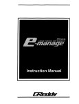
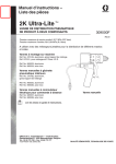
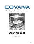
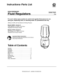
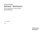
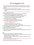
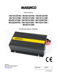
Operating Manual
High Viscosity Dispense Valve
Item # 984594
OPEN
Item # 984594
CLOSE
Label # 8901197
Warnings
INJECTION HAZARD
Spray from the valve, hose leaks, or ruptured components can inject fluid into your body and cause
extremely serious injury, including the need for amputation. Fluid splashed in the eyes or on the skin
can also cause serious injury.
• Fluid injected into the skin might look like just a cut, but it is a serious injury. Get immediate
medical attention.
• Do not point the valve at anyone or at any part of the body.
• Do not stop or deflect leaks with your hand, body, glove or rag.
• Be sure the valve trigger safety operates before dispensing.
• Lock the valve trigger safety when you stop dispensing.
• If the nozzle clogs while dispensing, fully release the trigger immediately.
• Follow the Pressure Relief Procedure on page 5 whenever you: are instructed to relieve
pressure; stop dispensing; clean, check, or service the equipment; and install or clean the nozzle.
• Tighten all fluid connections before operating the equipment.
• Check the hoses, tubes, and couplings daily. Replace worn, damaged, or loose parts
immediately.
• Permanently coupled hoses cannot be repaired; replace the entire hose.
• Do not remove any spring guard that is used to help protect the hose from rupture caused by
kinks or bends near the couplings.
EQUIPMENT MISUSE HAZARD
Equipment misuse can cause the equipment to rupture or malfunction and result in serious injury.
• This equipment is for professional use only.
• Read all instruction manuals, tags, and labels before operating the equipment.
• Use the equipment only for its intended purpose. If you are uncertain about usage, call your
Henkel Sales Representative.
• Do not alter or modify this equipment.
• Check equipment daily. Repair or replace worn or damaged parts immediately.
• Do not exceed the maximum working pressure stated on the equipment or in the Technical Data
for your equipment. Do not exceed the maximum working pressure of the lowest rated component
in your system.
• Use fluids and solvents which are compatible with the equipment wetted parts. Refer to the
Technical Data section of all equipment manuals. Read the fluid and solvent manufacturer’s
warnings.
• Do not use hoses to pull equipment.
• Route hoses away from traffic areas, sharp edges, moving parts, and hot surfaces. Do not
expose hoses to temperatures above 180 degrees F (82 degrees C) or below –40 degree F (–40
degree C).
• Comply with all applicable local, state, and national fire, electrical, and safety regulations.
• Never use 1,1,1-trichloroethane, methylene chloride, other halogenated hydrocarbon solvents or
fluids containing such solvents in this equipment. Such use could result in a serious chemical
reaction, with the possibility of explosion, which could cause death, serious injury, and/or
substantial property damage.
2
NOT FOR PRODUCT SPECIFICATIONS
Loctite is a TM of Henkel Corporation, U.S.A. © Copyright 2007. Henkel Corporation. All rights reserved
3
NOT FOR PRODUCT SPECIFICATIONS
Loctite is a TM of Henkel Corporation, U.S.A. © Copyright 2007. Henkel Corporation. All rights reserved
Installation
Connections
•
•
•
The fluid inlet is 1/4 npt(f).
The fluid outlet is 1/4 npt(f) or 3/4–16 unf(m).
Air inlets are 1/8 npt(f).
Optional Conversion Kits
4
•
Item # 989158. Electric Switch style Handle Kit to convert a 984594 to a Hand-held Valve.
This is a conversion kit for Loctite® 984594 Dispense Valve. Includes an electric switch style
handle kit, housing, handle, trigger, and other parts necessary to convert the 984594 High
Viscosity stationary mount dispense valve to a hand-held valve.
•
Item # 989157. Pneumatic Switch style Handle Kit to convert a 984594 to a Hand-held
Valve. This is a conversion kit for Loctite® 984594 Dispense Valve. Includes a pneumatic 4-way
valve with housing, handle, trigger and other parts necessary to convert the 984594 High
Viscosity stationary mount dispense valve to a hand-held valve.
NOT FOR PRODUCT SPECIFICATIONS
Loctite is a TM of Henkel Corporation, U.S.A. © Copyright 2007. Henkel Corporation. All rights reserved
Operation
WARNING
Pressure Relief Procedure
WARNING
The system pressure must be manually relieved to prevent the system from starting or spraying
accidentally. Fluid under high pressure can be injected through the skin and cause serious injury. To
reduce the risk of an injury from injection, splashing fluid, or moving parts, follow the Pressure Relief
Procedure whenever you:
• are instructed to relieve the pressure
• stop dispensing
• check or service any of the system equipment
• install or clean the nozzle
1.
2.
3.
4.
Shut off the air to the dispense valve, if applicable.
Shut off the air to the supply pumps.
Close the bleed-type master air valve (required in your system).
Hold a metal part of the valve firmly to the side of a grounded metal pail, and trigger the dispense
valve to relieve pressure.
5. Open the fluid drain valve (required in your system), having a grounded metal container ready to
catch the drainage.
6. Leave the fluid drain valve open until you are ready to dispense again.
Caution: If you suspect that the dispense needle or hose is completely clogged, or that pressure has not
been fully relieved after following the steps above, very slowly loosen the needle retaining nut or hose
end coupling and relieve pressure gradually, then loosen completely. Now clear the needle or hose.
Stationary Mounted Valve Operation
•
•
Be sure the air supply lines are connected correctly to the OPEN and CLOSE valve air ports.
To open or close the valve and maintain the open or closed status, a minimum of 40 psi (280
kPa, 2.8 bar) air pressure must be supplied and maintained at the OPEN or CLOSE port.
To open the valve:
1. Apply air pressure to the OPEN air port on the valve, and remove air pressure from the CLOSE
air port on the valve.
2. Maintain air pressure on the OPEN air port to keep the valve open.
To close the valve:
1. Apply air pressure to the CLOSE air port on the valve, and remove air pressure from the OPEN
air port on the valve.
2. Maintain air pressure to the CLOSE air port to keep the valve closed.
5
NOT FOR PRODUCT SPECIFICATIONS
Loctite is a TM of Henkel Corporation, U.S.A. © Copyright 2007. Henkel Corporation. All rights reserved
Operation
Electric Switch Style Hand Held Valve (optional)
•
•
•
•
Be sure the air supply lines are connected correctly to the OPEN and CLOSE valve air ports.
To open or close the valve and maintain the open or closed status, a minimum of 40 psi (280
kPa, 2.8 bar) air pressure must be supplied and maintained at the OPEN or CLOSE port.
The trigger only activates the electrical switch in the handle, which turns the remote solenoid on
and off.
Trigger the gun to turn the solenoid on. Release the trigger to turn the solenoid off.
Pneumatic Switch Style Hand Held Valve (optional)
The valve operation is such that there are only two valve conditions: either fully open or fully closed.
The valve is opened and closed by the internal air control valve. Trigger the gun to open the valve.
Release the trigger to close the valve.
Shaft Stroke Adjustment
•
•
•
Adjust the shaft stroke to balance the valve between “snuff-back” and “push-out”.
A long stroke will give maximum snuff-back but it may cause push-out when the valve opens.
Shortening the stroke of the shaft will minimize the material pushed out when the valve opens
and will also increase the material back pressure through the valve.
To adjust the shaft stroke:
1. Loosen the hex nut (44) from the adjustment nut (43).
2. Adjust the nut (44) along the adjustment shaft (42) to the desired position.
• The valve is at full stroke when the hex nut (44) is at the end of the adjustment
shaft (42).
• Adjusting the nut (44) on the shaft (42) towards the valve, or clockwise, will
reduce the stroke length.
• Adjusting the nut away from the valve, or counterclockwise, will lengthen the
stroke
3. Tighten the hex nut (44) to the adjustment nut (43)
6
NOT FOR PRODUCT SPECIFICATIONS
Loctite is a TM of Henkel Corporation, U.S.A. © Copyright 2007. Henkel Corporation. All rights reserved
Maintenance
Preventative Maintenance
There is a grease filled secondary seal/bearing area on the valve shaft. Every 10,000 cycles, or twice
each month, new grease should be flushed across this area. Use Loctite® ViperLube® clear highperformance grease or NLGI #2 grade equivalent. Each valve has two flush grease fittings.
To grease the valve:
1. Remove the grease fitting from one side of the gun.
2. Pump grease across the valve until clear grease comes out of the other side.
3. Reinstall the grease fitting.
Troubleshooting
1. Relieve the pressure.
2. Check all possible causes to the problem before disassembling the pump.
PROBLEM
CAUSE
SOLUTION
Valve does not open.
Insufficient air pressure
Air not exhausted from behind air
cylinder piston.
Shaft adjustment too far closed
Turn on or turn up air pressure.
Use four-way, relieving-type air valve.
Insufficient air pressure
Air not exhausted from behind air
cylinder piston
Blockage between needle and seat
Bad or missing gasket between seat
and housing
Needle worn out.
Turn on or turn up air pressure.
Use four-way, relieving-type air valve.
Nosepiece plugging up
Remove and clean.
Valve does not close.
Higher than normal
back-pressure
7
Adjust the shaft stroke as instructed on
page 6.
Remove and clean needle and seat.
Replace gasket (38).
Replace needle and seat.
NOT FOR PRODUCT SPECIFICATIONS
Loctite is a TM of Henkel Corporation, U.S.A. © Copyright 2007. Henkel Corporation. All rights reserved
Model 984594 High Viscosity Dispense Valve
8
NOT FOR PRODUCT SPECIFICATIONS
Loctite is a TM of Henkel Corporation, U.S.A. © Copyright 2007. Henkel Corporation. All rights reserved
Parts
Model 984594 High Viscosity Dispense Valve
Ref.
1
2
3
4*
5*
6*
7*
9*
10
11
12
13
14
15
16 *†
18
19
20 *†
21 *
22 *†
23 $
25 *
26
27 *}
30 *
31
35
36
37
38 *†
39 *†
40
41 *
42 }
43
44
Description
HOUSING, air cylinder
MANIFOLD, air control
SHAFT, air cylinder
O-RING, 010 buna-n
BEARING, air cylinder
O-RING, 222 buna-n
DOWEL PIN
O-RING, 006 buna-n
PISTON, air cylinder
CAP, air cylinder CAP, air cylinder
CLIP, internal 1.75
SCREW, drive
PLATE, identification
SCREW 10-32 x 0.375
O-ring, 014 Viton
FLUSH GREASE FITTING
LUBE HOUSING
U-CUP, urethane/EPR
BEARING, lube
U-CUP, Polymitet/EPR
SCREW, 1/4–20 x 2.25
SEAT, C2 carbide
HOUSING, fluid; stainless steel
NEEDLE, hardened stainless steel
GASKET, air cylinder
SCREW, 10–32 x 1.75
GREASE, 3 oz. tube (not shown)
GUN, grease (not shown)
COUPLER, flush grease (not shown)
Gasket, seat
O-ring, 014 PTFE
NOSEPIECE, stainless steel
RING, snuff-back
SHAFT, adjustment
NUT, adjustment
NUT, full hex, 10–32
Qty.
1
1
1
2
2
2
1
1
1
1
2
2
1
4
1
2
1
1
1
1
2
2
1
1
1
4
1
1
1
1
1
1
1
1
1
1
TM
* Included in Rebuild Kit # 989153 (with high density Parker Polymite
Rebuild Kit # 989154 (with PTFE main packing materials - optional).
main packing materials - standard) or
TM
† Included in Section Seal Kit # 989155 (with high density Parker Polymite
Rebuild Kit # 989156 (with PTFE main packing materials - optional).
®
main packing materials - standard) or
®
} Use Loctite Primer N 7649 and Loctite 242, 243, or equivalent (“blue” Loctite ) when assembling this part.
®
$ Use anti-seize lubricant (Loctite 56765 or equivalent) when assembling this valve.
9
NOT FOR PRODUCT SPECIFICATIONS
Loctite is a TM of Henkel Corporation, U.S.A. © Copyright 2007. Henkel Corporation. All rights reserved
Model 984594 High Viscosity Dispense Valve
Disassembly
1. Relieve all air and fluid pressure.
2. Disconnect the valve from the system.
3. Remove the four nosepiece screws (15), and pull the nosepiece (40) away from the valve.
Remove the snuff-back ring (41). See page 6.
4. Use an 1/8” pin punch in the needle hole (A) to unscrew the needle (27). If the shaft (3) spins,
insert a dowel pin in the shaft hole (B) to hold it steady, then unscrew the needle (27).
5. Remove the seat (25), gasket (38), and o-ring (39).
6. Remove the two fluid housing screws (23) and remove the fluid housing (26). Remove the
primary fluid seal (22) from the fluid housing (26).
7. Pull the bearing/lube housing (19) from the air cylinder (1). Remove the bearing (21), bearing oring (16), and secondary fluid seal (20). Remove the grease fittings (18).
8. Remove the C-clip (12) from the back of the air cylinder (1). Push the shaft (3) into the air cylinder
to dislodge the air cylinder cap (11). Remove the cap o-ring.
9. Remove the internal C-clip (12). Push the shaft (3) to dislodge the piston (10) assembly from the
air cylinder (1).
10. Remove the adjustment nut (44) from the shaft (3).
11. Remove the adjustment shaft (42) from the shaft (3).
12. Remove the pin (7), o-ring (9), and piston o-ring (6).
13. Use a 1/4” pin punch to knock out the bearings (5) and o-rings (4).
Pneumatic Switch Handle (if equipped)
1. Remove the trigger (56).
2. Loosen the set screw above the trigger safety. Pull off the handle (55).
3. Remove the four retaining screws (60). Pull the housing (50) and gasket (30) away from the air
cylinder (1).
Air Valve
1. Unscrew the stem guide (58).
2. Remove the trigger pin (59), o-ring (57), spool (49), spacers (51, 52), o-rings (46, 48) and spring
(47).
3. Remove the bushing (53) from the housing (50) with the screw (54).
4. Remove the screws (60) and lock-washers (61) from the air cylinder (1).
Electric Switch Handle (if equipped)
1.
2.
3.
4.
5.
Disconnect the power from the gun.
The switch, housing, and cable are not repairable. Replace these parts as a complete assembly.
Remove the trigger (56).
Loosen the setscrew above the trigger safety. Pull off the handle (55).
Remove the four manifold retaining screws (60). Pull the housing (50) and gasket (30) away from
the air cylinder (1).
6. Remove the bushing (53) from the housing (50) with the screw (54).
7. Remove the screws (60) and lock-washers (61) from the air cylinder (1).
10
NOT FOR PRODUCT SPECIFICATIONS
Loctite is a TM of Henkel Corporation, U.S.A. © Copyright 2007. Henkel Corporation. All rights reserved
Model 984594 High Viscosity Dispense Valve
Reassembly
Fluid Section
1. Lubricate the bearing (21), o-ring (16) and cup seal (20). Put the o-ring (16) on the bearing.
Carefully insert the seal (20) into the bearing recess, with the lips of the o-ring facing into the
bearing. Be careful not to damage the seal lips.
2. Push the bearing (21) seal end first into the housing (19). Be sure that the grease hole in the side
of the bearing lines up with the grease ports in the housing (19).
3. Holding the bearing (21) in place, push the bearing assembly over the shaft (3).
4. Lubricate the main fluid seal (22) and its cavity in the housing (26). Carefully press the seal, lipfirst, into the housing.
5. Push the housing (26) and seal (22) over the shaft (3) and up against the bearing housing.
6. Apply anti–seize lubricant (Loctite 56765 or equivalent) to the fluid housing screws (23) and
loosely install the screws to retain the housings. Do not tighten the screws yet.
7. Insert the gasket (38) and seat (25). These items are reversible and can be installed in either
direction.
8. Use Loctite® Primer N7649 and Loctite® TL242, 243, or equivalent (“blue” Loctite®) when
assembling the needle (27) and tighten to 15–20 in–lb (1.7–2.2 Nm).
9. Apply air pressure to the CLOSE port, or to the pneumatic trigger valve if installed. This will align
the shaft, seal, and bearing. Tighten the fluid housing screws (23) oppositely and evenly to 40–45
in-lbs (4.5–5 Nm).
10. Install the nosepiece (40) with the PTFE o-ring (39), screw (15), and snuff-back ring (41), if used.
The snuff-back ring has an internal bevel on one end which faces into the nosepiece. Tighten the
nosepiece screws to 15–20 in-lbs (1.7–2.2 Nm).
Air Cylinder Section
1. Lubricate the shaft o-rings (4) and the bearings (5) with grease. Insert o-rings into the air cylinder
(1) and air cap (11) cavities. See Page 3.
2. Press the bearings (5) flush into the air cylinder housing and air cap, trapping the o-rings (4).
3. Lubricate and reassemble the piston assembly; piston (10), o-ring (9), dowel pin (7), adjustment
shaft (42), o-ring (6), and shaft (3). Use Loctite® Primer N7649 and Loctite® TL242, 243, or
equivalent (“blue” Loctite®) when assembling the adjustment shaft (42). Tighten the shaft to 15–
20 in–lb (1.7–2.2 N_m). The shaft (3) should hang with some play to be self-aligning in the
bearing.
4. Lubricate the air cylinder (1) ID with grease. Push the piston (10) assembly into the air cylinder.
5. Orient the air inlet manifold (2) (if used) as shown. Match the gasket openings to the air ports.
11
NOT FOR PRODUCT SPECIFICATIONS
Loctite is a TM of Henkel Corporation, U.S.A. © Copyright 2007. Henkel Corporation. All rights reserved
Pneumatic Valve (if equipped)
1.
2.
3.
4.
5.
6.
7.
8.
9.
10.
11.
12.
Insert the spring (51) into the housing (50).
Lubricate and install an o-ring (46) into the housing.
Install a spacer (52), internal bevel first, into the housing.
Lubricate and install two o-rings (46) and the spacer (51).
Lubricate and install a spacer (52) with the internal bevel out, and o-ring (46).
Lubricate and install o-rings (48) on the spool (49). Insert the spool with the nub facing out.
Lubricate the pin (59) and insert it into the guide (58). Screw the guide with o-ring (57) into
the housing. Tighten it to 60–70 in-lbs (6.8–7.9 Nm).
Orient the gasket (30) to the holes on the air cylinder (1). Screw the air valve assembly to the
cylinder with the screws (60) and lock-washers (61). Tighten the screws evenly to 15–20 inlbs (1.7–2.2 Nm).
Screw the bushing (53) to the housing (50) with the screw (54). Tighten the screw to 140–150
in-lbs (15.8–16.9 Nm).
Attach the handle (55) with the setscrew.
Attach the trigger (56) with the grease fittings (18).
Test that the trigger safety works properly.
Electric Switch (if equipped)
1. The switch, housing, and cable are not repairable. Replace these parts as a complete
assembly.
2. The switch, housing, and cable assembly are not user serviceable and must be replaced
as an assembly.
12
NOT FOR PRODUCT SPECIFICATIONS
Loctite is a TM of Henkel Corporation, U.S.A. © Copyright 2007. Henkel Corporation. All rights reserved
13
NOT FOR PRODUCT SPECIFICATIONS
Loctite is a TM of Henkel Corporation, U.S.A. © Copyright 2007. Henkel Corporation. All rights reserved
14
NOT FOR PRODUCT SPECIFICATIONS
Loctite is a TM of Henkel Corporation, U.S.A. © Copyright 2007. Henkel Corporation. All rights reserved
Torque Specifications
15
NOT FOR PRODUCT SPECIFICATIONS
Loctite is a TM of Henkel Corporation, U.S.A. © Copyright 2007. Henkel Corporation. All rights reserved
Accessories – Spare Parts
16
TM
•
Item # 989153. Rebuild kit with high density Parker Polymite
9 for kit contents.
•
Item # 989154. Rebuild kit with PTFE materials - optional. See page 9 for kit contents.
•
Item # 989155. Section Seal Kit with high density Parker Polymite
page 9 for kit contents.
•
Item # 989156. Section Seal Kit with PTFE materials - optional. See page 9 for kit contents.
•
Item # 989159. Needle Packing Kit. Main fluid needle packing with PTFE reinforced U-cup with
stainless steel spreader.
•
Item # 989157. Pneumatic Switch style Handle Kit to convert a 984594 to a Hand-held
Valve. This is a conversion kit for 984594 Dispense Valve. Includes a pneumatic 4-way valve
with housing, handle, trigger and other parts necessary to convert the 984594 High Viscosity
stationary mount dispense valve to a hand-held valve.
•
Item # 989158. Electric Switch style Handle Kit to convert a 984594 to a Hand-held Valve.
This is a conversion kit for 984594 Dispense Valve. Includes an electric switch style handle kit,
housing, handle, trigger, and other parts necessary to convert the 984594 High Viscosity
stationary mount dispense valve to a hand-held valve.
materials - standard. See page
TM
materials - standard. See
NOT FOR PRODUCT SPECIFICATIONS
Loctite is a TM of Henkel Corporation, U.S.A. © Copyright 2007. Henkel Corporation. All rights reserved
Dispense Tips
17
NOT FOR PRODUCT SPECIFICATIONS
Loctite is a TM of Henkel Corporation, U.S.A. © Copyright 2007. Henkel Corporation. All rights reserved
WARRANTY
Henkel expressly warrants that all products referred to in this Instruction Manual for Item # 984594 (High Viscosity
Dispense Valve) (hereafter called “Products”) shall be free from defects in materials and workmanship. Liability for
Henkel shall be limited, as its option, to replacing those Products which are shown to be defective in either materials
or workmanship or to credit the purchaser the amount of the purchase price thereof (plus freight and insurance
charges paid therefor by the user). The purchaser’s sole and exclusive remedy for breach of warranty shall be such
replacement or credit.
A claim of defect in materials or workmanship in any Products shall be allowed only when it is submitted in writing
within one month after discovery of the defect or after the time the defect should reasonably have been discovered
and in any event, within (12) months after the delivery of the Products to the purchaser. This warranty does not
apply to perishable items, such as (fuses, filters, lights, etc.). No such claim shall be allowed in respect of products
which have been neglected or improperly stored, transported, handled, installed, connected, operated, used or
maintained. In the event of unauthorized modification of the Products including, where products, parts or
attachments for use in connection with the Products are available from Henkel, the use of products, parts or
attachments which are not manufactured by Henkel, no claim shall be allowed.
No Products shall be returned to Henkel for any reason without prior written approval from Henkel. Products shall
be returned freight prepaid, in accordance with instructions from Henkel.
NO WARRANTY IS EXTENDED TO ANY EQUIPMENT WHICH HAS BEEN ALTERED, MISUSED,
NEGLECTED, OR DAMAGED BY ACCIDENT.
EXCEPT FOR THE EXPRESS WARRANTY CONTAINED IN THIS SECTION, HENKEL MAKES NO
WARRANTY OF ANY KIND WHATSOEVER, EXPRESS OR IMPLIED, WITH RESPECT TO THE
PRODUCTS.
ALL WARRANTIES OF MERCHANTABILITY, FITNESS FOR A PARTICULAR PURPOSE, AND OTHER
WARRANTIES OF WHATEVER KIND (INCLUDING AGAINST PATENT OR TRADEMARK
INFRINGEMENT) ARE HEREBY DISCLAIMED BY HENKEL AND WAIVED BY THE PURCHASER.
THIS SECTION SETS FORTH EXCLUSIVELY ALL OF LIABILITY FOR HENKEL TO THE PURCHASER IN
CONTRACT, IN TORT OR OTHERWISE IN THE EVENT OF DEFECTIVE PRODUCTS.
WITHOUT LIMITATION OF THE FOREGOING, TO THE FULLEST EXTENT POSSIBLE UNDER
APPLICABLE LAWS, HENKEL EXPRESSLY DISCLAIMS ANY LIABILITY WHATSOEVER FOR ANY
DAMAGES INCURRED DIRECTLY OR INDIRECTLY IN CONNECTION WITH THE SALE OR USE OF, OR
OTHERWISE IN CONNECTION WITH, THE PRODUCTS, INCLUDING, WITHOUT LIMITATION, LOSS OF
PROFITS AND SPECIAL, INDIRECT OR CONSEQUENTIAL DAMAGES, WHETHER CAUSED BY
NEGLIGENCE FROM HENKEL OR OTHERWISE.
Manual P/N: 8901435, Date: 08/2007
18
NOT FOR PRODUCT SPECIFICATIONS
Loctite is a TM of Henkel Corporation, U.S.A. © Copyright 2007. Henkel Corporation. All rights reserved