1
I Important Information
Please read this instruction manual carefully, and proceed with the installation ONLY if you fully
understand this manual. Make sure to pay attention to all the "Important/" "Warning!" and "Cautionl"
messages through out the manual.
Important!
'"
'"
This product is legal for sale or use in California only on vehicles which may
never be driven on a public highway.
This product is only for vehicles with 12V (battery) systems.
Warningl
"
Installation of this product should only be performed by a trained specialist, who is
very familiar with the automobile's mechanical, electrical, and fuel management
systems. If installed by untrained person, it may cause damage to the unit as well as
the vehicle.
'" Never tune the E-manage while the vehicle is moving.
'" Never tune the e-Manage on public highways. This can be dangerous to you and
others on the road.
'" When tuning and operating the vehicle in a garage, make sure that the garage is
equipped with a proper ventilation system.
'" After installation and tuning, make sure to clean up every thing that would interfere
the driver. Wires, tools, and laptop computer may interfere with the driver and cause
accidents.
" Avoid open sparks, flames, or operation of electrical device near flammable
substances.
Caution!
'"
'"
'"
'"
•
•
•
•
•
Improper tuning of the e-Manage can cause damage to the engine.
GReddy Performance Products, Inc. will not take any responsibility of damage
caused by improper installation or tuning.
Tuning should be performed only by a technician who fully understand the vehicle's
fuel management and ignition timing requirement for the engine being tuned.
Always use a proper air/fuel ratio meter when tuning the e-Manage.
Installation of this product requires modification of the vehicle's electrical system.
When making wire connections, be sure to remove the key from the ignition, and
disconnect the negative terminal of the battery.
Never short out the system. It can damage the unit as well as the vehicle's electrical
system.
Read and fully understand the wiring diagram before making any wire connection.
When connecting the connector, push it in all the way until you hear them click in
together.
2
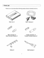
Parts List
*Make sure to check that all the following products listed are included in the box.
Main Unitx1
Male connector x2
Male Connector Sleeve x2
Splice x5
Main Harness x1
Female connector x 3
Female Connector sleeve x3
Split harness x1
I Parts List
Hex wrench xi
Adjustment tool xi
Tie Wrap i50mm x3
M4 screw x4
Instruction Manual xi
Necessary Basic tools
Other helpful items
Soldering Iron
Drill
Rag, cleaner, water
Electrical tape
Shrink-wrap
Voltage meter
Cutter
+ & - Screw driver
Crimping tool
4
Features
$
This unit is designed for 12V system.
• This unit is designed to control the factory injectors at 5 RPM points with the airflow
meter or MAP signal inputs.
• The built-in VTEC controller allows the adjustment of the VTEC shifting RPM point.
• With the "Self troubleshooting" feature, the unit will notify any errors in the system.
o With the Communication software (Sold Separately), the unit can be fine-tuned.
• Data logging and real time monitoring is possible by connecting with a PC
(Windows)
• Fine fuel tuning with an additional 16 RPM points.
• Ability to control larger injectors and Airflow meters.
• With the "DATA Protection" feature, the system can prevent any dangers of data
changes.
o With the Option Harness kit (Sold separately), more function can be added to the
system.
III
Ability to control the injector duty cycle, and Ignition Timing.
\\I
Ability to control up to 2 sub-injectors
• Ability to trace the fuel map on real time monitoring mode
*[VTEC] is a registered trademark of American Honda Motor Co., Inc.
I Installation
Please read this instruction manual carefully, and proceed with the installation ONLY if
you fully understand this manual. Make sure you read all the "Important!", "Warning!"
and "Caution!" messages through out the manual.
Important!
Installation of this product should only be performed by a trained specialist,
who is very familiar with the automobile mechanical and electrical systems.
If installed by untrained person, it may cause damage to the unit as well as
the vehicle.
• When using soldering iron and other tools for installation, make sure you
read and understand the tools user manual. Miss use of these tools can
cause injuries.
• When mounting the main unit, make sure it gets mounted in a safe area
that will not interfere with the driver. Improper mounting of the unit may
interfere with the driver and it can cause accidents.
4&
Caution!
When making wire connections, be sure to remove the key from the
ignition, and disconnect the negative terminal of the battery.
• Never short out the system. It can damage the unit as well as the vehicle's
electrical system.
• Read and fully understand the wiring diagram before making wire
connection.
iii
When connecting the connectors, push in all the way until you hear them
click in together.
iii
Please
• Be sure to wrap the spliced and soldered areas with electrical tape or with a
shrink-wrap.
Installation
'" Disconnect the negative terminal of the battery.
'" Locate the vehicle's ECU and disconnect the harness.
'" Splice the E-manage harness to the ECU harness power, ground and RPM input
source. Refer to the ECU diagram on Page 26-31, For splicing instruction, please
refer to page 7.
.. Cut the Airflow meter or MAP signal wire and install the male and female connector
on the cut end. (For RB26DETT, there are 2 signal wire, so cut and install the
connector on both wires) For malelfemale connector installation instruction, please
refer to page 7.
'" Connect the airflow input/output signal wire from the E-manage harness to the cut
wires.
• For Hot-wire, Flap or MAP type sensors, refer to the diagram on page 8.
o For Karman Vortex type sensor, refer to the diagram on page 8.
• For RB26DETT, refer to the diagram on page 9.
• For VETC equipped vehicle, refer to the diagram on page 9.
• Make sure to wrap all the area that was spliced or soldered with electrical tape.
'" Reconnect the ECU harness, and reinstall all the parts that were removed for the
installation.
'" Reconnect the negative terminal of the battery.
7
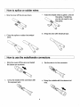
How to splice or solder wires
1. Strip the cover off the wire as shown.
"
Twist the striped wires to gather, and set
the splice. If soldering,
you do not need to use
the splice.
4. Wrap the area with electrical tape.
3. Crimp the splice or solder the twisted
wires.
How to use the male/female connectors
"
Strip the cover off the wire and install
the sleeve on as shown.
2. Set the wire in to the connector.
~,
3. Crimp the inside of the connector with
the exposed wire
4. Crimp the outside with the sleeve and
wire.
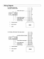
Wiring Diagram
For vehicles with hot-wire,
Flap type, and MAP sensor
6
White (Airflow Input 1)
I
I
I
I
o
I
I
o
I
)(
I
I
I
I
I
Green (Airflow 0 utput)
Brown (RPM Signal)
,----_._--- Black (Ground)
.. __."_.,,-- Red (12V Power)
[;:J
Female connector
Q
Male connector
-+
Splice
~
""'"
c::
ECU
For Vehicles with Karman Vortex type sensor
~
,
Light Blue (Airflow inpu t signal)
I
I
I
)K
I
I
I
Purple (Airflow output s ignal)
Brown (RPM signal)
[~
' - - - - Black (Gound)
l)
'-----Red (12v Power)
L
[;:J
Female connector
o
Male connector
-+
Splice
ECU
I
Wiring Diagram
For RB26DETT
]~
I
I
t
White (Airflow Input 1)
. Yellow (Airflow input 2 J
~-,>
"---l'~~~
.,
0000
00000
I
i
:
.
,
i
1
~
I
I
.
L-
B.rown (RPM signal)Black (Ground)
_ .. Red (12V power) -
r:l
Female connector
(J
Male connector
-1
Splicer
Q
Green (Airflow outpu t)
~
-
I
~
ECU
For vehicles with VTEC engine
J~
, - - - - White (MAP input signal)
-. Yellow (VTEC output}
Ught Blue (TEC input)
!)(
qz
0000
00000
Green (MAP output signal)
.. 1\
'----- Brown (RPM Sign,--,
' - - -...... -.~ Black (Ground)
' - - _ _ _ Red (12V Power)
I
I
*:I
10
fapeup
I
.-...-t-tI
~~~
ECU
Splice
-Cut&
I
Female connector
o Male connector
-+
I
I
:X
_.. ,. Purple (VTM putput}
~
I
I
J
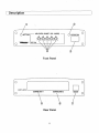
Description
o
AIR-FLOW ADJUST VOl. (±20%)
o
o
INTERACTION
o
o
Front Panel
0
0
M~~~m
[
CONNECTER 1
CONNECTER 2
@
@
Rear Panel
11
)D
BOOST
0
0
Description
~------------------
J
CD ACTIVE L.E.D.
• When the ignition is turned on, it will illuminate and flash GREEN.
o
When it reaches to the A.A. V. setting RPM range, it will illuminate and flash
ORANGE.
® AIR-FLOW ADJUST VOLUME (A.A.V.)
• This is used to set the 5 PRM points for fuel tuning.
® INTERACTION
• This is the port to communicate with PC using the optional software that will be
sold separately.
@ INTERACTION L.E.D.
1. This will illuminate when there is a connection with PC.
® CONNECTOR 1
• This is the port for the harness that is included with the unit.
@ CONNRCTOR 2
.
'" This port is used for the optional harness that is sold separately, to add more
features to this unit.
(J) Pressure sensor connection port
'" Pressure sensor can be added to the system to add more features with the use
of the software (sold separately)
12
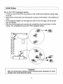
Initial Setup
Caution!
Make sure to perform the initial setting before starting the vehicle.
Rotary switch setting
It
First, using the Hex wrench supplied with the unit, remove the front cover of the unit.
• From the list of ECU Wire Location Chart on page 26-31, look up you vehicle and set
the first three left rotary switches.
Remove the front cover
[ Initial Setup
CD @ @
@ @
Rotary Switch Setting
CD Number of cylinder selector
@ Air-flow Type Selector
@ Air-flow Type Selector
Set the above selector according to the Vehicle Signal Location Chart.
@ VTEC Point Volume (VPV)
This volume switch is used to change the VTEG change over point.
@ VTEC Airflow Adjust Volume (VAAV)
This volume switch is used to compensate for the difference in the fuel map caused
by the adjustment in the VTEC change over point.
Warning!
The rotary switches are very sensitive, make sure to use the supplied tool to
turn the switches, and do not use excessive force.
• Vehicles with out VTEC, this completes the initial setup. Place the front cover back
on.
• For the vehicle equipped with VTEC, follow the next procedure.
14
Initial Setup
Set up for VTEC equipped vehicle
To set the unit for the VTEC, the jumper on the circuit board inside the casing needs
to be set.
iI
Remove the circuit board, by removing the 2 screws on the bottom, and carefully pull
it out.
• By following the diagram on this page and chart on the next page, set the jumper
pins accordingly.
• After the all the jumpers are correctly set, reinstall the circuit board back in to the
casing. This completes the set up for VTEC equipped vehicle.
e
(0
ICllol--.....~-....
3 JP3 1
1910' 0 )
3 JP3 1
JP6
I '0' 0)
12
3 JP2 1
(0
'010'
....&.
~
c...
0'"'0
JP? o....&.
1l2E.J2 ~
1 JP72
I 10 10 )
mEl
. tJP42
Caution!
Make sure all the jumper setting is correct. Improper jumper installation can cause
damage to the unit as well as the vehicle.
15
Initial Setup
Jumper #
Vehicle with
Air-flow meter,
MAP sensor
(SeUing from Factory)
'"
Vehicle with
VTEC Engines
.,
JP1
1.~2
+-
JP2
1 ~'2
+-
JP3
1 -....·2
2 -3
JP4
OPEN
1 ......... 2
'.
----
.'
-
.
. ',
'"
JP5
OPEN
+-
JP6
OPEN
1- 2
+-
JP7
.'.
,
OPEN
By following the diagram on the previous page and chart on this page, set the jumper
pins on the JP3, JP4, and JP7.
For the location that shows "1-2" or "2-3" in the chart, place the jumper to the pins to the
indicated location so that the corresponding pin numbers are jumped (connected).
For the location that shows "OPEN" in the chart, do not jump the pins at the indicated
location.
*When removing the Jumper to "OPEN" a connection, place the Jumper on to one side
of the pin to prevent the Jumper from getting lost.
16
Mounting the Main Unit
Important!
When mounting the main unit, make sure it gets mounted in a safe area that
will not interfere with the driver. Improper mounting of the unit may cause
damage to the vehicle as well as the unit. It can also cause accidents.
Cautionl
• Avoid mounting the main unit in the area where there are excessive
dust, and moisture. Also avoid a direct sun light, and area that will
get direct heater airflow.
• Try not to just cover the unit up with floor mat or carpet.
Please!
If you are using a double-sided tape, make sure you clean the surface with a
cleaner to remove any oil and dust.
(I
Mounting procedure
By using the provided screws and some kind of brackets, secure the main
unit on the floorboard.
17
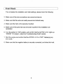
Final Check
This completes the installation and initial settings, please check the following.
2. Make sure all the wire connections are correct and secure.
3. Make sure that the wires are neatly secured and tucked away.
4. Make sure the main unit is securely mounted.
5. Make sure all the parts that was removed to perform this installation are
reinstalled.
6. Turn the ignition to "ON" position, and confirm that the ACTIVE l.E.D. lights up
"GREEN". If it doesn't, check the Troubleshooting Guide" section.
7. Start the engine and confirm that the ACTIVE l.E.D. is "NOT" displaying any
error code.
8. Make sure that the negative battery is securely connected, and close the hood.
lR
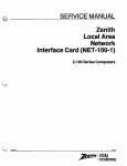
About the Fuel Adjustment
This unit reads the airflow or pressure sensor input signal of the factory system, and
calculates the intake air volume. Then with the front panel adjustment setting, it corrects
the airflow signal to the ECU to achieve the desired fuel delivery.
• About the AIR-FLOW ADJUST VOLUME switch (A.A.V.)
1. When the unit is powered up, the ACTIVE L.E.D. illuminate "GREEN" (solid)
• By using the supplied adjustment tool, turn the A.A.V. clockwise (+ adjustment) or
counter clockwise (- adjustment), the unit will go in to "Adjustment Mode". The
adjustment range is ±20% (at 1% increments).
• If you turn the A.A.V. to the desired setting, the ACTIVE L.E.D. will illuminate (solid).
When the A.A.V. is turned back to 0%, the ACTIVE L.E.D. will flash "ORANGE"
• If do not make any adjustment for over 2 sec. The ACTIVE L.E.D. will flash the
current setting in "ORANGE" twice. Then it will go back to "GREEN" and lock in the
setting.
• To adjust to the desired setting, repeat the steps 3 .... 4.
19
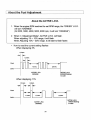
About the Fuel Adjustment
About the ACTIVE L.E.D.
1. When the engine RPM reaches the set RPM range, the "GREEN" L.E.D.
will turn "ORANGE".
(At 2000, 3000, 4000, 5000, 6000 rpm, it will turn "ORANGE")
2. When in "Adjustment Mode", ACTIVE L.E.D. will flash.
When adjusting 1% - 10% range, it will flash.
When Adjusting 10% ...., 20% range, it will start to flash faster.
• How to read the current setting flashes
When displaying 3%
0.2 sec.
Flash
~.Osec.
1.5sec.
Solid---!
ACTIVE L.E.D.
ACTIVE L.E.D.
GREEN flashing
or solid
ORANGE
When displaying 11 %
0.5 sec.
0.2sec.
Flash
1.0sec.
2.0 sec.
1.5 sec.
Solid---!
ACTIVE L.E.D.
GREEN flashing
or solid
ACTIVE L.E.D.
ORANGE
20
I
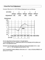
About the Fuel Adjustment
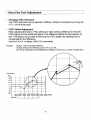
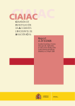
Example: When the A.A.V. SET RPM and Adjustment is set as following:
SET RPM
4
5
2
3
2000rpm 3QOOrpm 400Qrpm 5000rpm 6000rpm
Adjustment ..5%
-10%
+5%
+10%
+5%
1
Adjustment
+20
+15 ------ ------ ------ ------ ------ -----+10
~-----
------
+5
o
- 5
-10
-15
-20
.
4sno
.
I - - -....................~------ ~ ---- -- y-- ------ ------ ------
o
1000 2000 3000 4000 50006000 7000 8000 RPM
SET RPM
1
2
4
3
5
The fuel adjustment will be as shown in the graph above.
The rpm between the A.A.V. Adjustment points will be calculated with the before and
after of the adjustment points.
Example: From the graph above, the 4500 rpm points will be between A.A.V. 3 and
A.A.V.4. So, the adjustment point will be +7.5%.
Also, the adjustment before 2000rpm will be the A.A.V. 1 value, and above 6000rpm will
be the A.A.V. 5 value.
21
About the Fuel Adjustment
Changing VTEC shift point
@
The VTEC shift point can be adjusted ±1000rpm (100rpm increments) by turning the
V.P.V. on the front panel.
1&
VTEC Airflow Adjustment
When adjusting the factory VTEC shift point, there will be a difference in the ECU
VTEC signal and the actual shift signal. This difference affects the fuel injection as
well. This feature can be used to fine-tune the VTEC system by adjusting fuel to
compensate for the difference.
Use the V.A.A.V. to adjust ±1 0% (1 % increments) .
Example:
Factory VTEC shift pOint 5000rpm
Change shift point to 4000rpm, and V.A.A.V. to -2%.
2% will be subtracted from the4000rpm to 5000rpm of the A.A.v. ( shown in dotted line)
Adjustment
+20
+15
+10
+
5
o
• 5
-10
t----I--"""'".
-15 --- .. - -- ••• - .--.-- .--.• - ._ ••• -20
o
""N._ .- ••• -
••••••
r~
1000 .2000 3000 4000 5000 6000 7000 8000 RPM
seT RPM
1
2
3
4
5
22
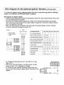
Wire Diagram for the Optional Injector Harness (sold separately)
To control the main injectors, and sub injectors, e-Manage Injector Harness is required along
with the e-Manage Support Tool software, and Windows base P.C.(laptop).
Injector Signal
• Connect to the vehicle's Injector signal wires. Refer to the "Vehicle Specific ECU wire location
chart" at the end of this manual for the proper location of each wire. Make sure that you connect
the same number of wires as the engine's cylinder number. (Excludes Rotary engines)
., For Rotary engines, you can wire only the primary or secondary injector signal or both.
.. If the vehicle does not have the same number of injector signal wire as the number of the engine's
cylinder number, group 2 wires in to one. See the example diagram below.
Example 1
Example 2
(6 cylinder angina with
3 injector signal wire)
ECU
[;l Malo connector
() Female connector
I- Splice
(Engine Control Unit
Eeu
(Engine Control Unil~
!
)~-
)
))<~-
--_. -----_.-~. ~~ N
fj m:tl ~
«
A)-
)-
)
)
' - - - - - PltR
I J CH-S)
' - - - - - - L B / R (I f J CH-6)
- - - - - .- BIR (VJ Ground ) ~-t-+-t
d)
®
PIR • PufJ?le/Red
WIR • White/Red
BIR • Black/Red
YIR - Yellow/Red
G/A· Green/Red
O/R • Orange/Red
PUR • Pink/Red
BUR· Blue/Red
LBIR • Ught Blue/Red
Sub Injector Signal
• When using the IIJ CH-A, IIJ CH-B for sub injectors, set the jumper JP5 and JP6 in the e-manage
main unit to "1-2" from "Open" .
., When using low resistance injectors dropping register is required in-line as shown below.
Dropping
Register
Fuse
(5-10A)
Battery
I/J CH-A or CH-B·-------'\;f-c~~ . _ - - + terminal
(For low resistance injectors)
' h'
"t)
(For h19
resistance InJec ors
I/J CH-A or cH-B--·----~-l
21
Fuse
(5-10A)
Battery
-----~---- + terminal
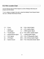
Wire Diagram for the Optional Ignition Harness (sold separately)
To control the ignition timing, e-Manage Ignition Harness is required along with the e-Manage
Support Tool software, and Windows base P.C.(laptop).
Wire diagram for Ignition Signal
.. Please read the instruction included with the Ignition harness kit, and proceed with the wiring only if
you fully understand the instruction.
.. Connect to the vehicle's Ignition signal wires. Refer to the "Vehicle Specific ECU wire location
chart" at the end of this manual for the proper location of each wire. Connect the ignition channel
wire in the engine's firing order.
,. Make sure that wires are connected in the firing order and jumper setting is correct. Improper
wiring and setting can damage the ignition coil.
!
feu
Example
i
(Engine Control Unill
Male connector
Cl Female connector
r:J
t Splice
~
1606f
'IIf
p:
- ~~----BJW (CHl IN)-----+!-", ,
O/w(eHlIN)
'f',:
------- P1W (CH4IN}--, i I:
L
=~
I r--LE/W {CHG IN)---- ~ 1I I:
~ ik
:':,::
',,-LEIS (CHG
~. :! i i:
Il t --PIlB (CH5 OUTr--i: : I:
----~- PIlW
(CHS IN)-
If:
1 ,,~J 3 - ¥il
rrll!J
II G-r:;_gJj
I
!
-
"PIS (CH40Un
VIS (CH3 au
' - - - - - V / B (CH3IN)
OIB (CHZ 0
------"----~
(CHI
~
e-manage IIG Channel
CK-l
CK-2 CH-3 CH-4 eH-S CH-6
----- i - -
f----
3. 4. 6. 8 cylinder distributor
t
"-
Inline 4 cylinder group ignition
tl,4
t2,3
Horizontally opposed 4 cylinder
t',2
t3,4
Inline 4 cylinder individual Ignition
tl
t3
t4
tZ
Horizontally opposed 4 cylinder
tl
t3
t2
t4
.---
:
..
---[--1
t5,2 t3,4
V6 group Ignition
tl,4
t2,5
t3,6
tl
tS
t3
t6
t2
t4
I'
I!:
Inline 6 cylinder individual ignition
: I':
V6 individual ignition
tl
t2
t3
t4
t5
t6
'
: l:
,',:
138 (FC3S. JC3SE)
tT
tL
208 (JCESE)
tT
I
I
t
I
i!
13B (FD3S)
•
,
tl,6
tL
On Hondas set the jumper pins JP 1 and JP2 to 2-3. (see
Page 14-15)
After wiring, if the tachometer, or not firing occurs, set the
jumper pin JP2 to 2-3. (Specially on Toyota)
On Honda EG type vehicles, the bottom third pin from the'
right on the 26 pin is also an ignition signal. Group the 2 wire
together.
24
~-~--
tTl
.--
,
:
-~-.-,
•
-,
Inline 6 cylinder group ignition
OUT}---
I
I
tT2
tL
------ t----,
i
Error Code Chart
How to read the error codes
When there is s system error, the ACTIVE L.E.D. will change to RED and start flash rapidly.
1. If this occurs, shut down the engine immediately. Turn the IG key to the "ON" position to go the
Check Mode.
2. While in check mode, the red flashes will start to flash all the stored codes.
3. Count the red flashes to check the code.
4. Turn the IG key to "OFF" position, and fix the problem.
* When the Support Tool (sold separately) is used to tune the e-Manage, check the Error Code
Chart on the Support Tool Manual.
0.5 sec
-
ON
OFF
0.2 sec
4.0 sec
--
.......
i-
1.5 sec
2500c
1-1 r
Error code [111
CODe
11
12
13
Error
Airflow Signal 1
input error
Airflow Signal 2
input error
Karman Vortex
sensor input error
r'"
.
-
r'
..
r'"
.......
4.0 sec
--I
Error CO<le {13]
Error description
Incorrect wiring or disconnected Airflow Signal 1
Incorrect wiring or disconnected Airflow Signal 2.
Incorrect Jumper setting (JP3).
Incorrect wiring or disconnected Karman Signal.
Incorrect Jumper setting (JP4).
Incorrect VTEC signal input wiring.
Incorrect Jumper setting (JP4).
15
VTECSignal
input error
Airflow voltage
output error
16
VTECSignal
output error
Incorrect VTEC signal output wiring.
Incorrect Jumper setting (JP3).
14
Incorrect Airflow Signal output wiring.
25
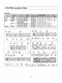
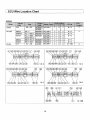
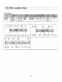
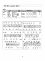
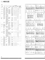
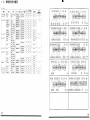
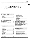
IECU Wire Location Chart
Use the following Table and Wire Diagram to set the e-Manage initial setup and
properly wire the harness.
* If your vehicle is not listed in the chart, contact the GReddy Product Support Dealer
near you or GReddy Performance Product.
+8
(#*
..... Power
~RPM
Injector Signal
t* ...- NO. '* Ignition Signal
E' +--Ground
I
~NO.*
Signal
Th
+-- Throttle Signal
Ar
+--Airflow/Pressure signal
VT
+--VTEC Signal
VM
+--VTM Signal
#E
~Injector
Ground
II· ti ...-RPM & Ignition Signal
i:!~:~~) ~NO.
itL
* &NO. '* Ignition Signal
...- Leading Ignition Signal
* Trailing Ignition Siganl
# P*'i
NO. '* Primary Injector Signal
(#'5*) ~ NO. '* Secondary Injector Signal
, t T*
~ NO.
~
26
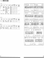
I ECU Wire Location Chart
TOYOTA
27
ECU Wire Location Chart
H-3
Integra
2
8
A
4
* Vehicle
with H - 3
VTM signal onfy-
-2R
--------------------
ECU Wire Location Chart
NISSAN
SKYLINE
N-10B
29
LECU Wire Location Chart
MITSUBISHI
CD
M-1
M-2
I ECU Wire Location Chart
MAZDA
*Adaptor required (Japanese spec only)
®
Ar
MA-5 :
/
(#$2)
#~1)
MA-6
MA-9.
!
MA-8
~1
2.
!f[ll~IJ1~ .j}13L ~~
t--::3:)1
~:~ I
.If-rt
ffirt
I:"'-:/ /ff~.it
ITI- ~ ;;~-~-;1~ -f; ;O)~~-~P*~ : _,lt~C~PR J
_ __
97.82JZ-GTE
TY HW-5
6
2
4
T-17_ ~_-",pg!
JZS161
91.10-97.7
. JZS147
7.-77
93.5-97.7
2JZ-GTE
JZA80
4
O, __
88.9-93.4
lG-GTE
TY FL-3
I 4
T-1
GA70
-~~-~~~-~~~~-~~~--+T~Y~P~R~-1-4-~+-1~4-+--~+-T~-~13~--~-91.5-96.7
1JZ-GTE
1'J77
JZZ30
lG-GTE
TY FL-3
I 4
T-1
GZ20
88.1-91.4
1JZ-GTE
?-'lIT
T-17
JZXll0
00.9: TY HW-6
------TY
HW-4
T-16
f-J-ZX100
96.9-00.8
JZX90- - - -' 92.10-96.8
!
TY PR-l
~=1]
--JZX81
90.8-92.9
_ _ _ _+-_~T~-10
---------2
I
ST205
94.2-99.7
3S-GTE
~')tJ
------j
MR-2
93.10-99.7 3S-GTE
SW20
10
I
8910 939
__
93.10 97.12 3S-GE
TTY PR3 ; 2 -4 2 T-ll
T-2
89.10 93.9
4A-GZE ---TYFL~4--2
4" A
T-5
86.8-89.9
AWll
!-:o-:--;:--=--;:----4·.-A'-GE
--TYJ'R:3
2
T-3
84.6-89.9
T-14 .J E!Gic-",pg
T)l;T") ' / 7 SXE10
3S-GE
TY HW-l
,
98.10
1
G-FE---=-TCPR-3+
T-18
, GXE10
~~---r~~-----l~~~~~~4~A-_~GE
T-2
vc::'-95.5-00.7
TY PR-3
AElll
T-8
91.6-95.4
4A-GE
AE101
TYJL-l
T-2
4A-GE .AlT)
TY_PR-3
AE92
89.5 91 5
~-O---=-C---l
4A-G E
87.5 89.4
AE86-- ---8:C3:':.5~_--:8C::7--:.4----l
I
~~~-~~~~-~~~--+'~~~~~~~~:~~-+~-ol
~~~=~~~~'~~~~~~~~
'~~.~_~L_~.~_~_ -=:-+----'-:-+---~~.--+- ~ =~
-r
t-
:-d
I
7. '" -
L.---;-;:-
EP91
EP82
EP7l
NCP31i35
NCP30
77/;I;.:::]i NCP21i25
NCP20
"7'''; 'J .y
NCP12
NCP16
SCPll
I ri1 ':; "J
NCPll
SCP10
bB
31
,TY]R-l
; 9512-98121 4E-FTE
89.12-95.11 ,4E-FTE (MiT)
4E-FTE (A/T)
92.1-95.11
89.12-91.12
2E-T
86.1-89.11
lNZ-FE
TY HW-3
00.22NZ-FE
99~13::'
lNZ-FE
I TY_HW-3
I
'2NZ-FE
lNZ-FE
TY_HW-3
99.82NZ-FE
TY HW-2
lSZ-FE
lNZ-FE
99.8TY HW-3
TY HW-2
99.1lSZ-FE
T-9
I
T-12
,
j
T-12
T-12
i
T-12
32
ffg~
ll!:li
",1::/'
EK9
EK4
~EK9
EK4
EK3
, EG6
,
1/7"/7
EG4
DC2IDB8
b------
/v'h,-e'
B86
J7::J-t..:'
CF4
----CD5
T::J-t..:'?::J> CF6
CE1
AT,,)/?:j> RF1
RF2
~----
.If-~
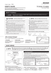
98.9-00.9
I/::;'/1fg~
B16B~ HN]R-1
B16A(VTEC)
91.9
95.8
95.91-;:-;::----93.5-95.8
i 93.596.12-97.993,9-97,8
'97,1094,3-97,9
96,5-
B16B(VTEC)
B16A(VTEC)
D158(VTEC)
, 816A (VTEC)
D158 (VTEC)
818C (VTEC), HN_PR-1
H
1
ECU
~Ilt,;pli
4
I
H 2
-----H-3
i
I
-~;--
2
8
A
HN PR-1
HN - PR-1
2
2
8
8
A
A
HN - PR-1
2
8
A
HN_PR-2
2
8
8
B18~
H22A
F20B
F22B
F208
F228
8208
CPlt~
,
Di5B(VTEC)
97.6 98.8
95.9-98.8
:;(1' 'Y70)~:iE
1
2
3
2
8
A I
-t! :.-<t-ligl)
!
I
H-1
H-2
H-5
H-2
H-1
H-3
H-1
H-3
H-4
4
5
5
5
5
Honda
33
34
.11
Jf~;;t
, {/7{:j'{Q45
~jl;
G50
Z32
JIlvi" {Z
1
AiJ171/ BNR34
ER34
BCNR33
ECR33
BNR32
HCR32
' AT-V'?
D-l/)v
.'<'!GNC34
WC34
C35
"
C34
C33
.-
it7-1-D
A31
I
--
:;.., )vr.:'}'
S15
S14
89.11-97.9
89 7
. -
VH45DE
NS HW-1
VG30DETT NS_HW-2
VG30DE
RB26DETT ,NS HW-6
RB25DET
NS HW-5
RB26DETT NS HW-6
RB25DET
~-NS HW-3
RB26DETT NS HW-6
RB20DET
'NS HW-3
RB26DETT NS HW-6
RB25DET
NS HW-5
RB25DET
NS_HW-5
99.198.5-----95.1-98.12
95.1-98.4
93.8-94.12
89.8-94.12
89.5-93.7
97.1096.9,97.694.9-97.5 I
94.1-94.8
---91.1-92.12 RB20DET
88.12-90.12
90.8-94.8
- - - - RB20DET
: 88.9-90.7
99._1_=-___ ~ SR20DET
96.6-98.12
, 180SX
RPS13
RS13
7')(,,-/,\-1" U14
1"/1);1.-7
P11
]7-"'=-)[., . PNW10
35
__91.1-93.9
89.3-90.12
'96.8-99.1
91.1-96.7
89.3-90.12
97.997.9' 95.8-98.7
2
0
I
3
o
I
0
1
0
0
7
7
7
7
7
7
7
7
0
0
0
0
0
o
2
5
2
5
4
4
1
2
NS HW-4
NS HW-3
NS HW-4
NS_HW-7
7
7
7
0
0
0
0
3
2
3
4
4
4
16
I
0
0
0
I
4
5
N -4
,
4
N 4
N -6
I
I
I
I
I
:8==
'~
N
10
I
N 10,
N -6
4
N-5
4
,
~-.---
0
4
;l
~lI!lllipfi
N4
!
ECU
I
N-1
N -3
-if=fo-I
-~-~~
I
NS HW-10
NS HW-8
CP.~
5
4
7
INS HW-S
CA18DET
SR20DET
i
1
8
7
NS_HW-3
9310-~
PS13
~-
A1""TO)~:;t
I./'l/~~ -t!/-!j--II~IJ
7
9
7
---::J
1
'
I
1
N -8
4
I
N -2
N-9
N-2
N -8
-~
I
4
-
NS- HW-10
CA18DET
SR20VE
NS_HW-11
SR20VE
j-NS_HW-11
SR20DET _ NS_HW-9
36
I:'~-
m~
GTO
Z16A
EC5W
EC5A
E39A
DE3A
v7:rh
i
:¥t'7/
FTO
in\;
, 90,10~
96,8~
96,8~
I/://1f~~ i:!:,rtt-~~IJ
6G72
6A13
6A13
MT KR-2
MT KR-2
MT KR-2
MT KR-1
MT_KR-2
87~10:::-92A
'4863'
- - - _ ..
-~-
97,2~
,-----
6A12
A1':;~0')~JE
1
6
6
6
3
6
I
2
8
8
8
8
8
3
4
4
4
3
4
, 96.2~97,1
7/-tJ--
I
37
96.2~
4G93
MT_KR-1
CP9A
CN9A
CE9A
CD9A
98,1~
4G63
MT_KR-1
96,8~97.12
2
2
2
I
;~--
M-4
M-8
M-3
_li_ -"~
3
8
3
3
I
8
3
M-5
,
4
I
M-2
93,12~96.7
92,10~93,11
M-1
M-4
M-4
i
94,10~96,1
_._----
[i!l't,!Apli
-------
94,10~96,1
DE2A
ECU
CPiI'-il-
I
I
38
l1!:l!
/xn~
~
I
_.RX-7
Jf~3t
~3t
~ESE
90.3~95.8
JC3SE
FD3S
90.3~95.8
95.12
FC3S
89.3~91.11
20B·REW
13B·REW
13B·REW
MZ FL·5
MZ FL·3
MZ,PR-1
A1'>
1 I
C
A
A
13B
MZ FL·2
MZ FL·1
MZ,HW-1
B
B
3
;rQ)f,ilE
CPlt>}
2
3
MA 1
A
D
A
B
MA-2
A
6 i_,~
MA-3
MA-6
A
A
MA-8
A
9
MA-5
A
0
MZ FL·4
MZ HW·2
3
3
A
A
I~:;/m~ t/"'t-l!~IJ
91.12~95.11
85.9~89.2
0
l"A9
NB8C
NB6C
~77~I)7'Sr;j/
39
BJFW
98.1~OO.6
! 98.1
.......
89.9~93.7
99.8~
BP·ZE
B6·ZE
---
FS
C
1
:
MA-7
MA-4
ECU
f,ial,lpfi
5
I
4
5
5
- - .5_ - -
40
1 2 . .~~IH~-%f.lLiii~
AJ\)~
_~I
Jf~>t
~>t
I
v;li:"1
BHS/BES
BDS/BGS
1:'-7'v;-tt
GC8/GF8
BCS/BFS
i
i7otVA)!
SFS
198.696.6-98.S
93.1O-96.S
189.2-93.9
198.9-00.8
196.9-98.8
92.11-96.8
198.9-
II/:/'/ffa~
EJ20
1EJ20 (MT)
1EJ20
EJ20
1
1
I EJ20
t
:.--tt-lI~ll
SB
SB
SB
SB
SB
I SB
SB
SB
HW-4
HW-3
HW-1
HW-2
HW-4
HW-3
HW-2
HW-4
A1';;rOJiltlt
I
3 1 CPli%
3 i
F-6
2 1
_'--j---,,--+-=-+---,-F_-4
_
-4 1 6 o 1
4
=1
6
1
F-S
3
6
3 1
F-3
3 1 6
F-1
4 1 6
F
-s
3 I 6
3 I
1
I
2
:d
~-I
ECU
,
I
...j ~"sI;\\PJi
I
~
[._______s __
1
:)I'1J\''J
_II
I
e;
~
b-
41
I
I
ff~~
L902S
LS02S
~>t
.:C/:/>ffaA
t'
-tt-lI~ll
./
SO PR-2
SO PR-3
I A1';;rOJ~lt I
1 1 2 I 3 I
CPli%
1
3 1 C
3 I C I 2
0-2
0-1
98.994.9-98.9
JB-OET
JB-JL
94.11-97.4
9S.S-98.6
K;-6Ao-_ _~:=-",~_+-'---I----'E-+ c------c:'---"'-.
K6A
I
I
I
ECU
,i):iii'I;\\PJi
I
b
42