1
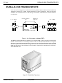
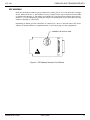
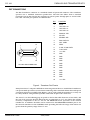
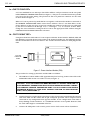
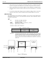
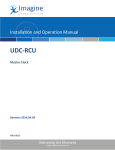
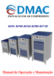
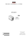
PRECISION INSTRUMENTS & SYSTEMS
USER'S MANUAL
PN 0014352001 B1
14352-B1
June, 2000
MA
DE
CO
RIAL
SE
L
NU
DE
MO
RA
E
NG
MB
ER
DE
IN
U.
S.
A.
PARALLEL
BUS
TRANSDUCER
MENSOR ® CORPORATION
CODE
201 BARNES DRIVE
SAN MARCOS, TEXAS 78666
SN
512-396-4200, FAX 512-396-1820
RANGE
WEB SITE http://www.mensor.com
PCS 400
PARALLEL BUS TRANSDUCER KITS
PARALLEL BUS TRANSDUCER KITS
A PCS 400 can be configured to communicate directly with the Mensor Model 15500 Parallel Bus
Transducer (referred to as PBT, external transducer or Bus Transducer). There are two kits
available: one to interface the PCS 400 with up to four PBTs, and another to connect from five
to eight PBTs.
1 of 4 PBT'S
Parallel Port
(PIM Port)
Remote Transducer
Port
1 of 8 PBT'S
SP EC IA L
RE MOT E
TR AN SD UC ER
PO RT
Cables
PIM
FE ATU RE S
“This equipment complies with the
requirements in Part 15 of FCC Rules for a
Class A computing device. Operation of this
equipment in a residential area may cause
unacceptable interference to radio and TV
reception requiring the operator to take
whatever steps are necessary to correct the
Cables
FUSE: 250V/1.5A
REFERENCE
MEASURE/
CONTROL
EXHAUST
SUPPLY
IEEE STD 488 PORT
SH1, AH1, T6, L4,
SR1, RL1, PPO,
DC1, DT1, E2, C0
PARALLEL PORT
SERIAL PORT
PCS 400 - Rear View
Figure 1 - Kit Configuration for Multiple PBT'S
The Model 15500 Parallel Bus Transducer is an external, high accuracy pressure measurement
module. The transducer is essentially identical to the PCS 400 internal transducers except for
the metal circuit board housing and the bus connector. The circuit board housing can be installed
with the 25 pin D-sub bus connector facing either end of the PBT. Each PBT has a battery backed
RAM chip which stores the transducer’s serial number, temperature compensation coefficients,
and calibration data.
CO
DE
SE
RIA
LN
O.
MO
DE
L
RA
NG
E
MA
DE
IN
U.
S.
A.
Figure 2 - Parallel Bus Transducer
MENSOR® CORP.
June, 2000
1
PCS 400
PARALLEL BUS TRANSDUCER KITS
PBT ADDRESS
Each Bus Transducer within a group connected to either port of a PCS 400 must have a unique
device address from 0 to 7. The address is set by a jumper on the top circuit board of each PBT
as shown below in figure 3. The jumper is normally set to an appropriate address at the factory.
However, it can be changed by placing the jumper on another pair of pins from W0 to W7 for
address 0 through 7, respectively.
Depending on which port the transducer is connected to, the PCS 400 will convert the device
address to another address as explained under 1a and 1b on page 4 in this supplement.
ADDRESS SELECTION PINS
W0
W1
W2
W3
W4
W5
W6
W7
Figure 3 - PBT Address Selection Circuit Board
MENSOR® CORP.
June, 2000
2
PCS 400
PARALLEL BUS TRANSDUCER KITS
PBT CONNECTIONS
The Bus Transducer connector is a standard female 25 pin D-sub connector. The transducer
operates over a modified Centronics parallel bus. The PBT bus differs from a standard
Centronics bus in that the PBT bus supplies 12 volt DC power through pins 13 and 25 of the
bus cable. The PBT port pinouts are shown below:
PIN
1
14
13
25
25-PIN D SUB CONNECTOR
FUNCTION
1
SCLK
2
UNIT SEL A0
3
UNIT SEL A1
4
UNIT SEL A2
5
RAM/CAL SEL
6
A/D SEL
7
SENSOR WR
8
RAM DATA IN
9
NOT USED
10
DRDY
11
P-A/D & RAM DATA
12
T-A/D DATA
13
+12 VDC
14
GND
15
GND
16
GND
17
GND
18
GND
19
GND
20
GND
21
GND
22
GND
23
GND
24
GND
25
+12 VDC
Figure 4 - Transducer Port Pinouts
Always have the PCS 400 power OFF when connecting external devices. Parallel Bus Transducers
can operate with up to 50 feet (total) of interconnecting cable. Standard ribbon cable and special
Y-junction connectors available from Mensor, can be used to link the transducers, or they can
be “daisy-chained” using standard parallel cables with 25-pin D-sub connectors.
The text of 1a on the following page is specific to the kit that adds from one to four PBTs, and
the text of 1b covers the kit that adds from five to eight PBTs to a PCS 400. These kits add the
necessary components to the PCS 400 for full MEASURE mode operation of the external
transducers. In addition, the PBTs can be connected to the MEASURE/CONTROL port to use
the external transducer in the CONTROL mode providing the full scale range of the PBT is not
greater than the primary range of the PCS 400.
MENSOR® CORP.
June, 2000
3
PCS 400
PARALLEL BUS TRANSDUCER KITS
1a – ONE TO FOUR PBTs
A PCS 400 modified for use with up to four PBTs will have a 25 pin connector on the rear panel
labeled REMOTE TRANSDUCER PORT (see figure 1). This port is a standard Centronics parallel
port except for the power wiring. The pin-outs for this rear panel bus connector are the same
as those shown in figure 4.
When a PCS 400 is powered up with this kit it recognizes each external transducer connected to
the REMOTE TRANSDUCER PORT at their device address. The PCS 400 then adds 8 to the
device address so that any of up to four bus transducers connected to this port are addressed
by the host as transducer 08 through 15 (0 + 8 through 7 + 8). To read one of these PBTs,
change the active transducer setting on the PCS 400 to the appropriate PBT address using the
LIMITS/ACTIVE TRANSDUCER menu selections.
1b – FIVE TO EIGHT PBTs
PCS 400
PARALLEL
PORT
INPUT
POWER INTERFACE MODULE
OUTPUT
Using more than four PBTs with a PCS 400 requires a Mensor Power Interface Module (PIM), PN
0014354001, to provide the necessary power to the external transducers. The PIM plugs directly
into the Parallel Port on the rear of the PCS 400, and the external transducers then plug into the
PIM.
5 TO 8
PBT'S
Figure 5 - Power Interface Module (PIM)
The procedure for setting up the PBTs and the PIM is as follows:
1.
The PIM has a built-in ribbon cable approximately four feet long. Connect this cable to the
PARALLEL PORT on the rear of the PCS 400 (see figure 1).
CAUTION: A PCS 400 WHICH HAS BEEN MODIFIED TO ACCEPT FROM ONE TO
FOUR EXTERNAL TRANSDUCERS WILL HAVE AN EXTRA REAR PANEL CONNECTOR LABELED ‘REMOTE TRANSDUCER PORT’. DO NOT CONNECT THE POWER
INTERFACE MODULE TO THIS PORT. CONNECT THE PIM TO THE PARALLEL
PORT, ONLY (SEE FIGURE 1).
2.
Connect from five to eight remote transducers to the 25 pin connector built into the opposite
end of the PIM. Use the cables and 25 pin T-adapters provided. The T-adapters can be
connected in any configuration that appears suitable. A star configuration at the PIM, or
daisy chaining at each transducer, or a combination of both, are acceptable. However, limit
the total cable length to a maximum of 50 feet.
3.
Connect the PIM power cord to an AC power source of 95 to 230 volts at 50/60 hertz.
MENSOR® CORP.
June, 2000
4
PCS 400
PARALLEL BUS TRANSDUCER KITS
4.
Power up the host PCS 400 only after all connections and power are completed at the PIM.
If power is not applied to the PIM first the PCS 400 will not recognize the remote transducers.
5.
The PCS 400 will add 16 to the device address of each transducer it recognizes on the
PARALLEL PORT so that the transducer addresses become 16 through 23 (0 + 16 through
7 + 16).
6.
To read one of these PBTs, change the active transducer setting on the PCS 400 to the
appropriate PBT address using the LIMITS/ACTIVE TRANSDUCER menu selections.
SPECIFICATIONS
The specifications for the Parallel Bus Transducer are the same as those shown in the
Specifications section of the PCS 400 manual PN 0014141001, where applicable, with the
exceptions as given below.
PBT
Size:
2.5" wide x 3.3" high x 4.56" deep
(6.35 cm x 8.38 cm x 11.58 cm).
1.9 pounds (0.86 kg).
Requires 9 to 15 VDC (12V nominal) @ 120 mA.
Approximately 30 minutes.
Weight:
Power:
Warm-up:
Transducer Volume (cubic Centimeters):
Table 1 – Transducer Volume
Pressure Chamber
Reference Chamber
Gauge Unit
0.6 cc
<20 cc
Absolute Unit
0.6 cc
N/A
Mounting:
The PBT may be mounted either vertical or horizontal. There are four 6-32
UNF threaded holes in the base, three 8-32 UNF threaded holes on the
pressure port side, and two 8-32 UNF threaded holes on the rear from
which to mount the transducer. See figure 6 for mounting hole patterns.
The PBT cover can be reversed such that the bus connector (*) can be on
either end.
2.30 (5.84cm)
*
Base
1.00 (2.54cm)
0.60 (1.52cm)
0.35 (0.89cm)
0.00
0.00
2.15 (5.46cm)
3.55 (9.02cm)
2.25 (5.72cm)
1.25 (3.18cm)
0.00
0.25 (0.64cm)
0.30 (0.76cm)
0.00
0.20 (0.51cm)
0.00
0.30 (0.76cm)
0.00
Figure 6 - PBT Mounting
MENSOR® CORP.
June, 2000
5
PCS 400
PARALLEL BUS TRANSDUCER KITS
PIM
Size:
5.1" wide x 2.7" high x 6.90" deep
(12.95 cm x 6.86 cm x 17.53 cm).
Weight:
2.0 pounds (0.91 kg).
Power:
84–264 VAC, 50 W maximum.
Outputs:
The PIM provides TTL level signals with pinouts compatible with a
standard IBM-PC Centronics printer port output.
WARNING: DO NOT CONNECT THE MENSOR BUS TRANSDUCER DIRECTLY INTO
A STANDARD IBM–PC CENTRONICS PARALLEL PRINTER PORT. DAMAGE TO
THE COMPUTER COULD RESULT! CONNECT THE MENSOR PARALLEL BUS
TRANSDUCER TO THE POWER INTERFACE MODULE OR A SPECIALLY EQUIPPED
PCS 400, ONLY.
Mounting:
It is not necessary to secure the PIM, however, four slotted holes are
provided in the base flanges for a secure mounting if desired. Orientation
is not a consideration as the module may be mounted in any attitude.
1c – HIGH PRESSURE PBT
The standard maximum range for external Parallel Bus Transducers is 1000 psi. However,
ranges of up to 10,000 psi (hydraulic) are available. Anyone interested in these higher ranges
can contact Mensor for details and specifications.
MENSOR® CORP.
June, 2000
6
PCS 400
PARALLEL BUS TRANSDUCER KITS
User's Notes:
MENSOR® CORP.
June, 2000
7