1
WCDMA Booster User Manual
Bravo Tech Incorporation Ltd
6185 Phyllis Dr. Unit D. Cypress,
CA 90630, USA
Tel: 717-230-8333
Fax: 714-230-8341
www.bravotechinc.com
Index
Index
1. Introduction .................................................................................................................... 1
2. General Description ....................................................................................................... 1
3. WCDMA Booster Block Diagram.................................................................................... 2
4. WCDMA Booster Connection......................................................................................... 3
5. WCDMA Booster Connection......................................................................................... 3
6. Outline Drawing.............................................................................................................. 4
7. Interface ......................................................................................................................... 5
8. System Installation ......................................................................................................... 5
9. Maintenances and Managements .................................................................................. 6
9.1 System maintenance ............................................................................................ 6
9.1.1 Routine maintenance .................................................................................. 6
9.1.2 Indicator lights............................................................................................. 7
9.2 System management ............................................................................................ 7
9.2.1 Alarm range setting..................................................................................... 7
9.2.2 Power amplifier and Low noise amplifier gain setting and calculation......... 8
10. System Specification.................................................................................................... 9
Page: i
WCDMA Booster User Manual
WCDMA Multi-Carrier High Power Booster
User Manual
1. Introduction
This manual contains information and procedures for installation, operation, and
maintenance of the WCDMA Multi-Carrier High Power Booster.
2. General Description
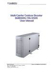
The WCDMA Multi-Carrier High Power Booster, shown as Figure 1 and Figure 2, is a
feed-forward; in-line power amplifier operating in UMTS band for a coverage enhancement
application. This multi-carrier based product platform provides higher downlink power and
improved the uplink sensitivity at the same time. The WCDMA booster can also work with
customized BTS to extend capacity of original BTS with a low system total cost. The
WCDMA booster is designed for outdoor application with IP65 environmental protection and
outdoor fans.
The WCDMA booster system topically needs 220Vac power supply
Figure 1 WCDMA Outdoor Booster System
The enclosure contains up to a RF MCPA, an AC power supply module, duplexer assembly,
a combiner, a monitor and gain setting module, four bypass relays, two LNA modules, a
modem, a control board, five cooling fans.
1
WCDMA Booster User Manual
Table 1 Composing of WCDMA Booster
Item
Description
Quantity
1
Multi-carrier Power Amplifier (MCPA) Module
1
2
AC Power Supply Module
1
3
LNA Module
2
4
Duplex Module
3
5
Modem (Remote control and Alarm Monitoring)
1
6
Control Board
1
7
Combiner Module
1
8
Bypass Switch
4
9
Fan
5
Figure 2 WCDMA Booster Inside View
3. WCDMA Booster Block Diagram
The following figure shows the system block diagram of the WCDMA Booster.
2
WCDMA Booster User Manual
Duplexer
Duplexer
Rx
BTS0
Tx/Rx
LNA
ANT0
Tx/Rx
Combiner
Tx
BTS
MCPA
Tx
Tx
BTS1
Tx/Rx
Filter
Rx
ANT1
Rx
LNA
Duplexer
Figure 3 Configuration Of WCDMA Booster
4. WCDMA Booster Connection
This product has the following functions:
z
Downlink output maximum power 40W, support multi-carriers amplify.
z
Support flexible downlink Input either duplexed or unduplexed
z
Support system full diversity
z
Downlink and uplink gain adjustable with wide dynamic range
z
Wide uplink input dynamic range
z
2.0dB uplink noise figure
z
Very high system efficiency
z
Extensive product monitoring and control (local and remote)
z
Centralized system control/display/alarms
z
IP65 environmental protection. Designed for indoor or outdoor installations.
z
Extensive protection for lightning, voltage surge, and any high failure rate assemblies
5. WCDMA Booster Connection
WCDMA Booster connects with BTS and antenna, shown as Figure 4.
3
WCDMA Booster User Manual
Figure 4 WCDMA Booster Connection
6. Outline Drawing
Figure 5 shows the outline drawing of WCDMA booster. Dimensions of WCDMA booster are
600,00
600mm x 430mm x 242mm(H x W x D)
242,50
430,50
Figure 5 Outline Drawing
4
WCDMA Booster User Manual
7. Interface
The interface of the WCDMA booster is shown in Figure 6. The specification of the interface
is shown in Table 2.
Figure 6 WCDMA Booster Interface
Table 2 WCDMA booster Interface Specification
Interface
Specification
AC220V
Input power interface for AC220V
BTS0
Connect to BTS main TX/RX port
BTS1
Connect to BTS diversity TX/RX port
ANT0
Connect to main antenna (TX/RX)
ANT1
Connect to diversity antenna (RX)
GND
Grounding Terminal
---
GSM Modem Antenna
8. System Installation
The supporting frames and screws are installed as Figure 7.
5
WCDMA Booster User Manual
Figure 7 WCDMA Booster Installation
9. Maintenances and Managements
This chapter describes the operation and maintenance of the WCDMA booster.
9.1 System maintenance
9.1.1 Routine maintenance
The booster provides the following protection functions: LNA protection, overpower
protection, VSWR protection, over-temp protection. In protection statements, the
WCDMA booster works in by-pass statement and sends out alarm signal by GSM
modem.
6
WCDMA Booster User Manual
9.1.2 Indicator lights
1.The WCDMA booster has 8 indicator lights for monitoring and alarm, as
shown in the following figure:
Figure 8 Monitoring And Alarm Indicator Lights
The specification of indicator lights is shown in Table 3
Table 3 Specification of indicator light
Item
1
2
3
Label
PA
-Power amplifier indicator light
LNA0/LNA1
-Low noise amplifier indicator light
PWR
-Power indicator light
PA-POW
4
5
-Power amplifier overpower indicator
light
VSWR
-VSWR indicator light
TEMP
6
7
-Power
amplifier
indicator light
temperature
WORK
-System working indicator light
Color
State
Specification
Green
Light
Power amplifier works normally
Red
Light
Power amplifier failure
Green
Light
Low noise amplifier works normally
Red
Light
Low noise amplifier failure
Green
Light
Power supply works normally
-
Dark
No power supply
Green
Light
PA power is normal
Red
Light
PA is overpower
Green
Light
VSWR is normal
Red
Light
VSWR is failure
Green
Light
PA temperature is normal
Red
Light
PA is over-temperature
Green
Spark
System working normally
Red
Spark
System working failure
9.2 System management
9.2.1 Alarm range setting
Generally, the manufacturer has finished alarm range settings. User needn’t to reset the
range. Alarm range reference is shown in Table 4:
7
WCDMA Booster User Manual
Table 4 Alarm Range Setting
Item
1
Indicator light
Alarm
LNA0/LNA1
Range
Over current
Upper limit:200mA
Down limit:42mA
Referential current:100mA
2
PA-POW
Over power
3
VSWR
Over VSWR
Power amplifier shut down power value: 47dBm
Over VSWR alarm and shut down: 5.0
Over VSWR restart :3.0
4
TEMP
Over temperature
Over temperature alarm and shut down power amplifier: ≥95
Over temperature restart: 75
9.2.2 Power amplifier and Low noise amplifier gain setting and calculation
1.Gain setting
Figure 9 Downlink And Uplink Gain Setting
Shown as Figure 9, ‘TX’ and ‘RX’ switch are 4 bits code switch, ‘0’ for switch up and ‘1’ for
down. The TX numbers are 1 - 2 - 4 – 8 in turn. The RX numbers are 8 - 4 - 2 – 1 in turn.
Table 5 Power amplifier and low noise amplifier gain setting
Item
Label
Description
Number
Range
1
TX
Downlink PA gain setting
0~15
Adjust range:0~15dB
2
RX
Uplink LNA gain setting
0~15
Adjust range:0~12dB
For example, the setting numbers of Figure 16 are shown in Table 6:
Table 6 A example of power amplifier and low noise amplifier gain setting
Item
Label
Switch number
Description
1
TX
8
PA Gain:8dB
2
RX
12
LNA Gain:12dB
8
WCDMA Booster User Manual
2.Gain calculation
Below descript the calculation of the gain of downlink PA and uplink LNA.
Table 7 Symbol Description
Item
Symbol
Description
1
PBTS
BTS output power
2
Pin
Booster input power
3
Loss
Gable loss
4
Gdown
Downlink PA gain
5
Pout
PA output power
6
Gup
Uplink LNA gain
The max output power of PA is 40W (46dBm), the gain of PA is calculated as the
following formula:
Gdown=Pout-Pin= Pout-(PBTS-Loss) = 46dBm-(PBTS-Loss)
On the assumption that the output power of BTS is 20W (43dBm), the cable loss is 3dB,
than the gain is:
Gdown=Pout-(PBTS-Loss) =46dBm-(43dBm-3dB) =6dB
To avoid the over-power alarm of the booster, set 1dB redundancy, and adjustable step
is 1dB, so the PA gain is set 5dB.
Gup compensates the insertion loss of feeder and booster. For engineering experience,
Gup = 8~12dB is recommended.
10. System Specification
Table 8 System Specification
RX Characteristics
Frequency Range
Specification
1920-1980MHz
Instantaneous Bandwidth
60MHz
Max Gain over frequency and temperature
12±1 dB
Adjustable Gain Range
0~12dB
9
WCDMA Booster User Manual
Flatness over Frequency
Noise Figure
≤±1dB
≤1.8dB (typical)
≤2.0dB (maximum)
Insertion Loss (Bypass Mode)
≤2.6dB
Output 1dB Compression (max. Gain)
+12dBm
Output IP3 (max. Gain)
+25dBm
Return loss(VSWR)
18dB active(1.29:1)
14dB bypass(1.5:1)
RX to TX Rejection
>80dB
TX Characteristics
Frequency Range
Specification
2110-2170MHz
Instantaneous Bandwidth
60MHz
Number of Carriers
Support multi-carriers
Output Power
40W
Maximum Input Power
43dBm
Gain
0 - 15dB(+/-0.5dB)
Adjustable in 1dB step
Gain Flatness
+/-1dB
Gain Variation Over Temp
+/-1dB
Spectrum Masks and Spurious Emissions
Meeting WCDMA 3GPP requirements
System Characteristics
Return loss(VSWR)
Specification
BTS Ports
14dB (1.5:1)
Antenna Ports
14dB (1.5:1)
Bypass Insert Loss
<0.5dB
Monitor & Control (LCD and Keypad)
Forward Power, Reverse Power, Temp, LNA
Conditions (for both), PA Conditions, TX Gain
Setting, RX Gain Setting, DC Voltage
Alarm & Protection (Form C type)
Overpower Shutdown, Over Temp Shutdown,
Loop Fail Shutdown, Reverse Power Shutdown,
DC Fail Shutdown
Power Input
220V AC
Environmental Characteristics
Operating Temperature Range
Specification
-20˚C to +55˚C
10
WCDMA Booster User Manual
Cold Start Temperature
-40˚C
Storage Temperature
-40˚C to +85˚C
Waterproof
IP65 (Except Fans)
Humidity
5%~95%
EMC
ETS 300 342-3
Mechanical Characteristics
Material
Specification
Steel& Aluminum Frame
Weight
58Kg
Dimensions(H x W x D)
600mm x 430mm x 242mm
Connectors
BTS Ports
7/16 DIN female
ANT Ports
7/16 DIN female
Fan
Fans support outdoor working
Reliability Characteristics
MTBF
Specification
MCPA
100,000 hours
Rectifier
70,000 hours
Other Parts
150,000 hours
11