1
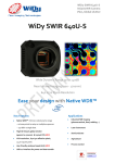
Pembroke Instruments, LLC 120 Stanford Heights Avenue San Francisco, CA 94127 USA [email protected] Tel. 415-860-4217 www.pembrokeinstruments.com WiDy SWIR 640U-S User’s manual Nov. 2014 – V1.0 *Products and specifications discussed herein are for evaluation and reference purposes only and are subject to change by NIT without notice. Products are only warranted by NIT to meet NIT’s production data sheet specifications. DOCPC14003V01 WiDy SWIR 640U-S USB digital VGA InGaAs Camera Features High QE InGaAs from 900nm-1.7µm, VGA Resolution , 640 x 512 effective pixels, 15µm square pixels, 12.3mm diagonal High Dynamic Range thanks to its patented Solar Cell pixel structure: 140 dB – no illumination saturation Native WDR™: Intrinsic wide dynamic range - no knee points to setup – no multiple exposures – 140 dB in a single shot. Single USB 2.0 output - compatible with Windows OS (driver Vista, 7.0, 8.0) Ease of Use – Delivered with GUI WiDyVISION Low power consumption and small form factor Applications Key Performances Industrial NIR Imaging (pharmaceutical, food, welding …) Sensor NSC1201-SI Laser instrumentation Resolution 640 x 512 pixels Semiconductor Operating Mode Global shutter (Snapshot) Agricultural Materials InGaAs Process Control Pixel size 15um x 15um QE 80% Dimensions 49 x 49 x 33 mm Output USB 2.0 14bits Camera Interface USB 2.0 Dynamic Range >140dB – Log response Lens mount CS/C Mount Frame rate Up to 60fps Power Consumption <1,5W Operating Temp -40°C +70°C Weight <125 gr Ordering information 9SMC1201IY31UC0E : “WiDy SWIR 640U-S” 2 WiDy SWIR 640U-S USB digital VGA InGaAs Camera Table of contents Features ................................................................................................................................................... 2 Applications Key Performances .............................................................................................. 2 Ordering information............................................................................................................................... 2 1 CAMERA POWER UP REQUIREMENTS ................................................................................... 6 1.1 Power Up requirements ........................................................................................................... 6 1.2 Cleaning information ............................................................................................................... 6 2 CAMERA FUNCTIONS ................................................................................................................ 6 3 CAMERA ASSEMBLY.................................................................................................................. 7 4 5 6 3.1 Camera layout.......................................................................................................................... 7 3.2 Lens Mount.............................................................................................................................. 8 CAMERA INTERFACING ............................................................................................................ 8 4.1 Power supply ........................................................................................................................... 8 4.2 Digital video Output ................................................................................................................ 9 4.3 Trigger (SMC connector) ........................................................................................................ 9 COMMAND AND CAMERA CONTROL .................................................................................... 8 5.1 Camera control ........................................................................................................................ 9 5.2 Camera command .................................................................................................................. 10 IMAGE PROCESSING ................................................................................................................ 11 6.1 AGC / manual settings ........................................................................................................... 11 6.2 Zoom on displayed image ..................................................................................................... 11 6.3 Color and filtering ................................................................................................................. 12 7 NUC .............................................................................................................................................. 11 8 RECORDING ................................................................................................................................ 12 9 MECHANICAL DETAILS ........................................................................................................... 12 9.1 Housing and details ............................................................................................................... 13 9.2 Dimensions ............................................................................................................................ 13 9.3 Lens and camera mounting.................................................................................................... 13 10 CAMERA CARE .......................................................................................................................... 12 10.1 Maintenance and return ......................................................................................................... 13 10.2 Electrostatic discharge (ESD)................................................................................................ 13 10.3 Cover glass damage ............................................................................................................... 13 3 WiDy SWIR 640U-S USB digital VGA InGaAs Camera 10.4 Camera housing ..................................................................................................................... 13 List of figures ........................................................................................................................................ 14 4 WiDy SWIR 640U-S USB digital VGA InGaAs Camera Thank you for purchasing the WiDy 640U-S InGaAs camera. This user’s manual details the features, functions and interfaces of your camera. The WiDyVISION software document is also available for detailed interface. Please contact support team at [email protected] for more information. Important: NIT reserves the right to change products or specifications without notice. 1 CAMERA POWER UP REQUIREMENTS 1.1 Power Up requirements The WiDy 640U-S is designed against damage from high voltage surge. However we recommend that you do to not use a voltage higher than 5V to ensure proper operations. All connections must be done before applying power. We recommend the USB power supply cable delivered with the camera. 1.2 Cleaning information Care is required when installing a new lens to prevent dust from entering the mount opening. However, if dust is present on the sensor window surface, you may clean the imager surface using cleaning materials. Acetone liquid and microfiber tools are recommended for removing dust and cleaning the sensor window. 2 CAMERA FUNCTIONS The WiDy SWIR 640U-S camera is a Near InfraRed camera (900-1700nm) especially designed for users in the industry, laser and process control domains whom are looking for Wide Dynamic Range, VGA resolution, reliable and ease of use solution in NIR imaging. WiDy SWIR 640U-S camera makes use of NSC1201-SI sensor, delivers video signal in digital 14 bits via USB 2.0 interface. It is delivered as a turn-key package including camera, software tools and cables in shock proof case allowing thus a quick and easy integration in any equipment platform. 5 WiDy SWIR 640U-S USB digital VGA InGaAs Camera Figure 1 - WiDy SWIR 640U-S with CS/C mount adaptor The WiDy SWIR 640U-S camera offers the following functions: - Different set-up possibilities through camera control o Frame rate o Exposure time o Trigger external or internal - Image post processing - Customized Non Uniformity Correction* : 2 points NUC, Bad Pixel Correction - Recording 3 CAMERA ASSEMBLY 3.1 Camera Layout The camera is assembled with multipart aluminum housing. 3 main elements compose the cameras, as described in the following figure: Front Optical Interface with CS-mount ring Camera Body Back Cover Figure 2 – Side view of WiDy SWIR 640U-S (*) Camera is calibrated at factory. User can calibrate the camera with its own parameters but can restore factory calibration using BPM file and NUC factory file ( See WiDyVISION manual). 6 WiDy SWIR 640U-S USB digital VGA InGaAs Camera An additional CS/C mount adaptor is systematically mounted on the camera for delivery. 3.2 Lens Mount The front optical interface and the CS-mount ring are factory adjusted to guarantee a CS mount lens compatibility. For customers using a C mount lens, an additional ring, supplied with the camera, needs to be mounted prior to the lens. However, in case of focus trouble, the CS-mount ring can be manually adjusted to be properly positioned with the sensor focal plane. This adjustment is done with a screw. 4 CAMERA INTERFACING The WiDy SWIR 640U-S is powered and provides a digital 14 bits video flux trough a single mini USB 2.0 connector. The camera parameters such as frame rate, Trigger control, NUC & BPM are controlled using the WiDyVISION software. Power supply is also available through the USB 2.0 connection. A trigger input/output is available through the SMC connector. The trigger setting is controlled with the WiDyVISION software. 4.1 Power supply The input power supply is available through the mini USB2.0 connector (MOLEX - 5000751517). A standard USB voltage of 5V must be used for the camera. Never use a voltage higher than 6V. Figure 3 – USB2.0 connector 7 WiDy SWIR 640U-S USB digital VGA InGaAs Camera 4.2 Digital video Output The default video output is a digital 14 bits USB 2.0 output provided through the mini USB 2.0 connector 4.3 Trigger (SMC connector) The trigger control is done through a SMC connector (MULTICOMP - 26-09-TGG). The trigger can be configured as an input (from external to camera) or as an output (from camera to external) / The trigger input signal must be in the range of 0-3.3V. Never use a voltage input higher than 3.3V Figure 4 - SMC connector 5 COMMAND AND CAMERA CONTROL 5.1 Camera control The following Camera controls can be accomplished through the USB connection with the WiDyVISION Software. - Exposure time - Trigger - Frame rate 8 WiDy SWIR 640U-S USB digital VGA InGaAs Camera Important note: Operation mode of sensor (rolling or global) is automatically selected by camera once reference WiDy SWIR 320U, 640U, 640U-S is selected by user in starting menu. Figure 5 – starting menu WiDyVISION 5.2 Camera command A set of key information about camera (sensor reference, resolution, serial number of camera, frame count, FPA temperature) is accessible in the tool bar. For more information, refer to WiDyVISION software manual. 6 IMAGE PROCESSING 6.1 AGC / manual mode By default the WiDySWIR 640 is programmed in AGC mode. This means displayed image is automatically optimized between 8 000 and 16 000 counts (RAW output of sensor is in differential analog converted into 14 bits). This function can be deactivated manually by clicking “manual settings”. In manual settings, user can adjust by two slides the min and/or max values of displayed signal. 6.2 Zoom on displayed image A digital 2x zoom is available for user by clicking check box. 9 WiDy SWIR 640U-S USB digital VGA InGaAs Camera 6.3 Color and filtering Different menus for post processing display image (color, filter) are available for two different modes: AGC or manual settings. Histogram of image is accessible on the tool bar of GUI. For more information, refer to WiDyVISION software manual. 7 NUC The WiDy SWIR 640U-S you have purchased has been already calibrated in factory. When you will start the WiDyVISION software image displayed is pre-corrected at NIT factory (correction of bad pixels and 2 points calibration); the boxes “activate NUC” and “activate default BPR” are already ticked. User can make its own 2 points NUC and/or BPR. This operation requires careful respect of procedure described in WiDyVISION software. Important note: The serial number of camera is displayed at the foot of the tab of NUC. User must use different names for saving its own 2 points NUC and/or BPR. For more information, refer to WiDyVISION software manual. 8 RECORDING The WiDyVISION software allows to record still images ( png, jpeg, bmp) or videos (ptw, avi ) coming from camera. The image capture is accessible on the tool bar For more information, refer to WiDyVISION software manual. 10 WiDy SWIR 640U-S USB digital VGA InGaAs Camera 9 MECHANICAL DETAILS 9.1 Housing & Materials The WiDY SWIR 640U-S is composed of 3 parts (front panel with CS-mount ring, body, back panel). All these parts are anodized aluminum with a black finish. An additional CS/C-mount adaptor is anodized aluminum with black finish is also supplied with camera. 9.2 Dimensions Figure 6 – Front of WiDy SWIR 640U-S The WiDy SWIR 640U-S measures only 48.6 x 48.6 x 32.6 mm, hence making the camera perfect for small size OEM applications. Dimensions are given in mm. Figure 7 - WiDy 640U-S Dimensions (mm) 11 WiDy SWIR 640U-S USB digital VGA InGaAs Camera 9.3 Lens and camera mounting CS-mount ring is fully adjustable for back focus to support a wide variety of CS-mount lenses. A CS/C-mount adaptor is supplied with the camera to offer a compatibility with Cmount lenses. A Kodak 1/4 mounting hole is available for camera mounting and it can be used with a standard tripod mount. Figure - Kodak 1/4" mounting hole 10 CAMERA CARE 10.1 Maintenance and return. The WiDy SWIR 640U-S is guaranteed for one year providing normal conditions of use. Therefore, the WiDy 640U-S camera should be handled with care. The camera should not be exposed to liquid or shock environments. If an issue cannot be resolved, please contact New Imaging Technologies support at [email protected]. A returned Materials Authorization (RMA provided by NIT) may be used for the return. If the camera is under warranty, the camera will be repaired or replaced according to the terms of the warranty. If the camera is out of warranty, the repair will be quoted on an individual basis. 12 WiDy SWIR 640U-S USB digital VGA InGaAs Camera 10.2 Electrostatic Discharge (ESD) The WiDy SWIR 640U-S camera contains circuitry that can be damaged by electrostatic discharge. It is good practice to carry the camera in a static free container or bag. When the camera is not plugged in, the user should make sure that the working surface, and any tools used, are properly grounded. 10.3 Cover Glass Damage The camera sensor has a protective cover glass over the sensor. If the lens mount is removed, this cover glass is exposed at the front of the camera. It can easily become scratched, soiled or damaged. It is especially difficult to remove oil from it, so avoid touching with fingers. It is best to keep the lens mount on the camera to reduce the risk of physical damage. If the cover glass does get dirty or dusty, use clean, dry compressed air to blow away any dust. If further cleaning is required, use a lint-free, ESD safe soft cloth wipe and optical cleaning fluid (e.g. acetone liquid can be used). 10.4 Camera Housing If the camera housing becomes dirty, a soft cloth with an isopropyl alcohol solution can be used. 13 WiDy SWIR 640U-S USB digital VGA InGaAs Camera List of figures Figure 1 WiDy 640U-S ........................................................................................................................... 7 Figure 2 MOLEX - 500075-1517 mini USB 2.0 connector used for power supply and Camera interface ................................................................................................................................................... 7 Figure 3 Multicomp SMC connector (MULTICOMP - 26-09-TGG) ..................................................... 9 Figure 4 WiDy 640U-S Dimensions ..................................................................................................... 11 Figure 5 Kodak 1/4" mounting hole ...................................................................................................... 12 14