1
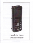
Handheld Laser
Distance Meter
User Manual
Symbols used
English
Congralulalions on the purchase of your
products.
Carefully read the Safety Instructions and the User
Ilanual before using this product.
AA
Hj.
ffi:T';:H
?::'i:
i",'nlt
The symbols used in the SaIety Instructions have the
following meanings:
A waRrruc,
Indicates a potentially hazardous situstion
or an unintended use which, if not avoided,
will result in death or serious injury.
?u,
"..=
understand these directions and adhere to them.
A caunou,
Indicaes a potentially hazardous situation
or an unintended use which,if not avoided,
may result in minor injury and/or in appreciable material,financial and environmen-
€
,
tal damage.
Important paragraphs which must be
adhered to in practice as they enabled the
product to be used in a technically correct
and efficient manner.
Use of the instrument
Permitted use
Measuring distances
Computing {unctions,e.g.areas and volumes
Indirect measurement
Addition and subtraction operations of measurement
Prohibited use
. Using the instrument without instruction.
. Using outside the stated limits.
. Deactivation of safety systems and removal
z
of explanatory and hazard labels.
. Opening of the equipment by using tools
(screw drivers, etc.), as far as not
specifically
permitted for certain cases.
. Carrying out modification or conversion of
the product.
. Use after misappropriation .
. Use of accessories from other
manufacturers
rithout the express approva-l
company.
scaffolding, when using ladders, when
measuring near machines which are
running, or near parts of machines or
installations which are unprotected.
. Aiming directly into the sun
. Deliberate dazzling of third parties; also in
the dark
. Inadequate saleguards at the surveying site
e. g.
wh en m eas u ri n g o n ro ad s, o.,
sites, etc.)
"
"i.r-"ti
o.t.
Limits of use
See
manuf acturers of non-Original acces s ories
for the products are responsible for developing,
implementing and communicating safety concepts for
their products. They are also responsible for the
effectiviness of these safety concepts in combination
with the products equipment.
Th e
Responsibilities of the person in charge of the
instrument:
of our
. Deliberate or irresponsible behaviour on
(
Responsibilities of the manufacturer of non-Original
accessories:
section "Technical Data ,,
The poduct is designed for use in areas perm
nently habitable by humans, do not use the product in
A wenmrxc
The person responsible for the instrument
must ensure that the equipment is used in
person is also accountable for the deployment
of personnel and for their accordance with the
instructions. This training and for the safety
of the equipment when in use.The person in
charge of the instrument has the following duties:
. To understand the safety instructions on
the product and the instructions in the
User Manual.
. To be familiar with local saf ety regulations
relating to accident prevention.
. To inform Leica Geosystems immediately if
the equipment becomes unsafe.
explosion hazardous areas or in
aggressive environments.
Hazards in use
a cAutrol:
As the original producer responsibility:
Watch out for erroneous distance measurements if the instrument is defective or if it has been
dropped or has been misused or modified.
Precautions:
Responsible for providing security products
include manual and origin of the pirts.
Carry out periodic test measurements. parti-
cularly after the instrument has been subject
to abnormal use, and before, during and alter
important measurements.
Make sure the optics is kept clean and that there
is no mechanical damage to the bumpers.
a cAutrol:
In using the instrument for distance measurements or for positioning moving objects (e.g.
cranes, building equipment, platforms, etc.)
unforeseen events may cause erroneous mea-
surements.
Precautions:
Only use this product as a measuring sensor,
not as a control device. Your system must be
configured and operated in such a way, that in
case of an erroneous measurement, malfunction of the
device or power failure due to installed safety measures
(e.g. safety limit switch), it is assured that no damage
will occur.
A wARNtNc:
Flat batteries must not be disposed of with
household waste. Care for the environment
Always prevent access to the product by unauthorized
oersonneland take them to the collection points
H
lY, provided in accordance with national
X or local provided in accordance with
/ Lt-{er\
national or local regulations.The
product must not be disposed of wit household
waste.Dispose of the product appropriately in
accordance with the national regulations in force in
your country.
Electromagnetic Compatibility (EMC)
The term "electromagnetic compatibility" is taken to
mean the capability of the product to function
smoothly in an environment where electromagnetic
radiation and electrostatic discharges are present, and
without causing electromagnetic interference to other
equipment.
awARNrwc:
The products conforms to the most stringent
requirements of the relevant standards and
regulations. Yet, the possibility of it causing
interference in other devices cannot be totally
excluded.
acAurroN:
Never attempt to repair the product yourself .
In case of damage, contact the local dealership.
Laser classification
I
nteg rated distancemeter
A A-@
The produces a visible laser beam which emerges from
the front of the instrument.
It is a Class
2 laser product in accordance with:
. IEC60825- I : 2OO7 "Radiation saf ety of laser
products"Laser Class 2 products:
Do not stare into the laser beam or direct it to
wards other people unnecessarily. Eye protection is normally afforded by aversion responses including the blink reflex.
AwAnnINc,
Looking directly into the beam with optical aids (e.g.
binoculars, telescopes) can be hazardous.
Insert batteries, observing correct polarity.
Close the battery compartment again.
o
J
Replace the batteries when the symbol
flashes permanently in the display.
Precautions:
Do not look directly into the beam with optical aids.
Aceurrou,
Looking into the laser beam may be hazardous to the
eyes.
F only
use alkaline or rechargeable
batteries.
€
R.-orr" the batteries before any long
period of non-use to avoid the danger ol
corrosion.
Precautions:
Do not iook into the laser beam. Make sure the laser is
aimed above or below eye level. (particularly with fixed
installations, in machines, etc.)
Labelling
!
effi
E-g
ffi
Ghanging the reference poin:
(mu ltifunctional endpiece)
The instrument can be adapted for the following
measuring situations:
. For measurements from an edge, fold out the
positioning bracket until it first locks in place.
. For measurements from a corner, open the
positioning bracket until it locks in place, then push
the positioning bracket lightly to the right to fold it out
fully.
built-in sensor automatically detects the orientation
of the positioning bracket and adjusts tlee zero point oI
the instrument accordingly.
A
lnserting/replacing batteries
1 Remove battery compartment lid and attach
handstrap.
. For measurements from an edge, fold out the
positioning bracket until it first locks in place.
-------.
. For measurements from a corner, open the
positioning bracket until it locks in place, then push
the positioning bracket lightly to the right to fold it out
fully. A built-in sensor automatically detects the
orientation of the positioning bracket and adjusts the
zero point of the instrument accordingiy.
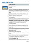
Display
o
Laser active
Reference
J
Indirect measurement (Pythagoras)
4
Delay measurement
Area volume measurement
Stored record
Data display
1
5
6
7
8
Display unit
Battery status
9
1
0
1 1
1
1
2
5
Hardware failure
The dynamic continuous measurement
Marking function
Operation error indication
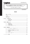
Ke ypad
T
a
Minus
ON / DIST (On/measuring) - button
Plus (+) - button
-
@
(-) - button
Ar ea / volum e- button
Angle button
a
o
E Indirect measurement
light/ Units-button
6
E Storage-button
Referenc e-butto n
(Pythagoras) - button
Background
@
Timing button
a Clearn/ off-button
ETE
@@@
@@9
r
Battery state ind icator
E
XD
D
rl
eatteryT5%
natteryS0%
eattery21%.
BatteryO%
can be shown on the disPlaY.
Standard supply part
lllumlnati ng disPlaY f@:)
@ brtto., (press short), the illuminating display can
off.
Laser Distance Meter
1 portable belt
2 battery
1 operatinginstructions
1 protective bag
1 warranty card
be turned on or
The Gorrection of
tilt sensor
@l to enter into the tilt sensor"
mode. Continuous-ifp..ss this button @ Iive times
Press this button
Measurements
long) - Press
ffi button (pressedmeasurement.
once again to change
the unit of distance
The following units are available: m (meter), ft (feet), in
(inch),
11 +
/ in (f eet - inch
1/ 16).
Beep
J brtto.r
aeain when the bottom of display shows 0'0; Then press
birtton I otr". to see the display shows 0' 1' Wait for
five secFnds and rotate the instrument by 180 degree'
:i:::;t:ll,t:f, ";."1?:?,1i:;li'-E:3J3:l;:1""'
Press this button @ ior exiting.
(press long). You can choose the beep on or
off as required.
Laser Continuous (-x-)
and hold down the key when switching on the
! eress
dEice until the character t .pp."." permanently in the
*:"il3tlJ:::".::.=*ltt;lJ;l:llTl'6'"'::"'"','f""8
and hold to switch the device and laser continuous
operation off.
Measuring with tripod
The reference must be appropriately adjusted in order
to be able to take correct measurements with a tripod.
You can switch the referenc. bV l@ button. The setting
of
'
",:L'ili t:: ?i:'.'.Ksvmbor
un
til
The
the
,F""J;::;:?,:iil".ix:*:1""1T3ffi.i:'"':1,""'n'
automatically after three minutes of inactivity'
Clear button
While making
@ ff,. last action is cancelled.each
single
o. volume measurements,
^E"
can be deleted and remeasured
measurement
in series.
Refenece setting
The default reference setting is from the rear of the
instrument.The display will show you.
@ P.ess this bution, a measurement will be
@ Press button to activate horizontai measurement in
the instrument. The following symbol
extended along as the reference edge. The
appears in the display-d
display will show youF-.
@ Pr... this button, will
measure the reference edge
fixed to the {orefront. The display will show youE
@ P.""" this button, the rear reference is set
again.
.
\
J
Timer (self-triggering)
@ Press this button to set a S-second time delay. or@
Level
You can choose the level gauge on or off as
required by press this bulto; (E)
until the desired time
delay is reached (max. 30 seconds).Once the key is
released the remaining seconds until measurement
(e.g. 29, 28,27 ...) are displayed in a countdown. The
last 5 seconds are counted down with a beep. After the
last beep the measurement is taken and the vaiue is
Press and hold down this button
Sinqle distance measurement
! ri."" ro acrrvare rne raser. ! rr""" agaln ro
trigger the distance measurement. The result
is displayed immediateiy.
displayed.
fffl.
Tilt measurement
G"fn. tilt
+ 45.
ffDuring
sensor measures tilts between
I
the measurement of tilt, the
be held without
instrument should
transverse
10').
tilt,
as far as possible, ( +
Horizontal measurement
.lf the button is active, the
horizontal distance is displayed in the summary line for
each distance measurement (up to max. + /-45" and up
tqlnax. a transverse 1i11 61 +/-10' ).
! eress the button to collect the measurement data,
and the data will be on the display. And the height
distance, horizontal distance, hypotenuse distance and
angle will be showed on auxiliary display in turn.
I
timer can be used for all
measurements.
Minimum/maximum measurement
This function allows the user to measure the
minimum or maximum distance from a fixed
measuring point. It can also be used as to
determine spacings.It is commonly used to measure
room diagonals (maximum vaiues) or horizontal
distances (minimum values).
! P.."" and hold down this button until you hear a
be-ep. Then slowly sweep the laser back and forth and
up and down over the desired target point(e.g. into the
corner of a room).
! e."== to stop continuous measurement. The
vdi-ues for maximum and minimum distances are shown
in the display as well as the last measured value in the
summary line.
! Pre"s it again to.take the second length
mEasurement (e. g. width).
The result is displayed in the summary line.
Volume
@l P.""" this button twice.
appears in the display.
!
Thel€gsymbol
Rress this button to take the
( e. g. length).
first length
m-easurem ent
I Press this button to take the second length
measurement (e.g. width).
f Press this'bitton to take the third length
measurement (e. g. height).
The volume then appears in the summary line.
Tilt measurement
El
Addition / subtraction
Distance measurinq.
! f fr. next measur.--..rt is added to the
orevious
one.
^J ffr. next
measurement is subtracted from
the previous one.This process can be repeated as
reouired.
! fn" last step is cancelled.
Area
El Pr.""
once.
The/Esymbol appears in the
display.
t
Press this button to take the
mEasurement
(e.
g. length).
first length
!
Long press this button once to activate the
sensor.The tilt degree data and tilt
tilt
symbollorlappears in the display.
er."" to measure the inclination and the distance.
-I
using
theorem.
eytt
iure you adhere to the prescribed
Make"gor""'
sequence oi measurement:
. Ai I target points must be in a horizontal or
vertical plane.
. The best results are achieved when the
instrument is rotated about a fixed point
(e.g. with the positioning bracket fully
folded out and the instrument placed on a
wall).
. The minimum/maximum function can be
used - see explanation in "Measuring ->
Minimum/maximum measurement". The minimum
value must be used for measurements at r ight angles
[:i:'i:'it$t.t':'i;3:J:'i'lt";:]i:ffi",'"'if
The instrument can calculate distances
'
"
summary line,the partial results in the
secondary line.(Such as:angle and distance.)
Ilbevelangle>45" ,Need to measure (2)
this button,closed angle sensor,
_p be measured
again point ( 1) in the
Shall-P..""
distance.After the measurement is completed, Keep the
instrument as horizontal as possible.
to trigger
I Pr."" and hold down thii button
^r-.r.^.-^-.^
laser
c-ontinuous
measurement, sweep +L^
the r^^^back and forth and up and down over the ideal target
noint'
to stop continuous measurement (2).
!TEe fr.""
result is displayed in the summary line,
the partial results in the secondary line'
(Such as:bevel edge and angled edge distance')
]fiff:ry::, lfil
to the target; the maximum distance lor all other
ffi;.
""il",nrr,n"
rirst measurement and
using2auxilliarymeasurements
e.g. for-rneasuring building heights or widths.
It is helpful to use a tripod when measurirg
^_.,-^^
three
of two
Lwuor
,rtaDur surErrL ur
heights that require thee measurement
measurements.
ilt'
@ press this button once, the display sho*s/.
The laser is switched on.
! ei* at the upper point (1) and trigger the
I
|
7
I
lndirect Measurement - determining a distance
using 3 measurements
@ Press this button twice; the display shows the
followine svmbol('The laser is switched on'
! ei* It in. rpp", point (1) and trigger the
measurement. After the first measurement the value is
adopted. The result is displayed in the summary
line,the partial results in the secondary line.(Such
as:angle and distance.)If bevel angle>45" ,Need to
measure (2)
@ Press this button.closed angle sensor,Shall be
mGasured again point ( 1) in the distance.
After the measurement is completed, Keep the
instrument as horizontal as possible.
! e.."" and hold down this button to trigger
cEntinuous measurement, sweep the laser up and down
over the ideal tareet point.
! P.."" to stoplontlnuous measurement (!! The
vElue is adopted-. Aim at the lower point and ! Press
this button to trigger the measurement (3). ThE result is
displayed in the summary 1ine, the partial results in the
secondary lines.
Storage of constants/h istorical storage
Historical storage
@ P.."" this button f or long time, the icon
(6
) will
show on the display , and the previous 10 results
(measurements or calculated results) are shown in
reverse order.
The!and jbuttons can be used for navigation.
Make it available constant for further calculations by
pressing @button.
--l
Technicaldata
ITEM
Message codes
,easuring range
A11
treasuflng a@umcy
message codes are displayed with either or
"Error". The following errors can be corrected:
100m instrumenl
+
Remedy
Cause
reflected light
too weak or too
strong,
M@surement time
too long
mbient
ight is too strong
1mm
620-690nms 1mw
I
2800
{ddwale eror
520-690nma
Cool dom or wm up
the instrument, External
Temperature will be
available lrom o.c to +40
\rea, Volume measuring
0.3"
0.3'
a
o
o
)ythagoras proposition
a
o
rlus
a
ndired measuremenl
o
a
Automatielly
Automati€lly
o
a
rm / maximum measuremenl
)isplay illumin6tion
r'lultifunctional end piece
)rctection against splashes and dt
'emperature range for Storage
10
t0
0.C to +40C
0C to +,lOC
-20t
5000
)attery life
to
.aser switch-off automati@lly
After 30 seconds
118 x4g x27
such
as
LR6 (AA) 2 x
Afrer 30
(
without battery )
l.sv
seMds
Afler 3 minutes
118,49 x27 nm
1509
150S
Veight
* maximum
frfr
to +7(rc
5oo0 to 8000 mesuement
After 3 minutes
strument switch{fi automati@lly
Meight
-20t
to +7OC
E00U measurement
LR6(M)2x1.5v
|attery selection
)imensions
tPg
tP 54
lrstoical storage
iwitch on / oJf the
nstrument sweral tlmes.
I the slmbol still appeds,
:hen your instrument may
>e defective. Please call
/our dealer Ior assistance.
t
o
a
a
o
a
method
lemperalure Enge ror uperaron
mw
t 45'
i
'lorizontal moasurement a@uracy
11.
'1
a
a
)ontinuous measurement
Chmge the light {or
measuring..
'
0.O5 to ao M
Typi€li2mmClas 2M ll
ihow beep
Temperature
too high ( +40'C ) or
too low ( OC )
-
lorizontal measurement range
Rmperation, change a
better surface reflecting or
using tilget plate.
lhe goal of the
*
mm
80m instrument
1mm
)islance measuromeniwiih lill sonsor
Calculation enor,
Receiving the
M'
Clas 2M ll
nspray accuaacy
.aser type
l2
Typiel
.aser classification
lcon
io ,00
o 05
(
without batery
)
deviation occurs under unfavourable conditions
bright sunlight or when measuring to poorly reflecting or
very rough surfaces. Measuring accuracy between 1O m and 30 m
may deteriorate to approx. + 0.025 mm/m, for distances above 3O m
to + 0.1 mm/m.
Measuring conditions
Measuring range
The range of 100m instrument is limited to 100m.The
range of 80m instrument is limited to 80m.
At night or dusk and if the target is in shadow
the measuring range without target plate is
increased. Use a target plate to increase the
measurement range during daylight or if the
target has poor reflection properties.
Target surfaces
Measuring errors can occur when measuring
toward colourless liquids (e.g. water) or dust
free g1ass, Styrofoam or similar semiperme-able
surfaces. Aiming at high gloss surfaces may deflect the
laser beam and lead to measurement errors.Against
non-reflective and dark surfaces the measuring time
may increase.
Gare
Do not immerse the instrument in water. Wipe
off dirt with a damp, soft cloth. Do not use
aggressive cleaning agents or solutions. Handle the
as you would a telescope or camera.
instrument
Warranty
The instrument comes with a one-year warranty.
This warranty effective premise is: according to the
company's operating instructions for correct operation,
processing,cleaning and maintenance of the tool, and
the tool is maintained good technical condition.This
means that in the tool can be used in the company,s
original components and spare
parts.This warranty is provided in the tool during the
whole life expectancy of the delective parts of the
repaired or replaced free of charge.If tlh"
due
to normal wear and in need of repair or replacement,
"o*porr"nt is
not in the warranty van.
All illustrations, descriptions and technical
specifications may be subject to change without prior
notice.
a;:r:: ::i j.a;l:{ii
-,=--
::J,i--:::,,.::-j:i:
.:::
,.:.-;;',
::
.,
: :-:t :: ,:
-- ... '
Serial number:
Product type:
Name ofpuchaser:
Address:
Product name: Laser distance meter
Date ofpuchase
_
Phone:
_
Zip code:
_
Distribution name:
Dealer seal:
Frdeiepaii-servie€s:,.,
-
...
The whole of laser distance meter-
Battery ttrget boild, hand stap, soft package, packaging and other auxiliary
equipments are not in the fiee maintenance runge.
:.'.'
rnce
Maintenance
Maintenancecentef
Replacement parts
Not registered of puchasing date on the waranty cild, the liee
maintenance service of this machine will be from the date of mmufacture
w