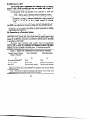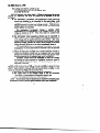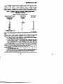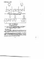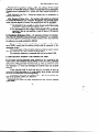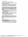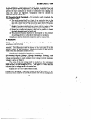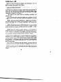
1
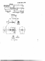
इंटरनेट
मानक
Disclosure to Promote the Right To Information
Whereas the Parliament of India has set out to provide a practical regime of right to
information for citizens to secure access to information under the control of public authorities,
in order to promote transparency and accountability in the working of every public authority,
and whereas the attached publication of the Bureau of Indian Standards is of particular interest
to the public, particularly disadvantaged communities and those engaged in the pursuit of
education and knowledge, the attached public safety standard is made available to promote the
timely dissemination of this information in an accurate manner to the public.
“जान1 का अ+धकार, जी1 का अ+धकार”
“प0रा1 को छोड न' 5 तरफ”
“The Right to Information, The Right to Live”
“Step Out From the Old to the New”
Mazdoor Kisan Shakti Sangathan
Jawaharlal Nehru
IS 9249-1 (1979): Safety requirements for indicating and
recording electrical measuring instruments and their
accessories, Part 1: Common safety requirements for
instruments [ETD 12: Measuring Equipment for Basic
Electrical Quantities]
“!ान $ एक न' भारत का +नम-ण”
Satyanarayan Gangaram Pitroda
“Invent a New India Using Knowledge”
“!ान एक ऐसा खजाना > जो कभी च0राया नहB जा सकता ह”
है”
ह
Bhartṛhari—Nītiśatakam
“Knowledge is such a treasure which cannot be stolen”
IS : 9249 ( Part
I ) - 1979
( Reaffirmed 2002 )
Indian Standard
SAFETY REQUIREMENTS FOR
INDICATING AND RECORDING ELECTRICAL
MEASURING INSTRUMENTS AND
THEIR ACCESSORIES
PART
-.
I
COMMON
FOR
SAFETY
REQUIREMENTS
INSTRUMENTS
( First Reprint JANUARY
UDC
.
621’317.7
1990 )
: 614’8
’
0 Copyright 1980
RUREAU
MANAK
INDIAN
OF
BHAVAN.
9
BAHADUR
NEW
Gr 6
.-
DELHI
STANDARDS
SHAH
ZAFAR
MARG
110002
February
1980
ISt9249(PartI)-1979
Indian Standard
SAFJWY REQUIREMENTS FOR
INDICATING AND RECORDING ELECTRICAL
MEASURING INSTRUMENTS AND
THEIR ACCESSORIES
PART I
COMMON
SAFETY REQUIREMENTS
FOR INSTRUMENTS
Electrical
Instruments
Sectional
Committee,
ETDC 48
ChUinlIn
PRO? ( DR ) J. K. C~XOUDHURY
Jadavpur University, Calcutta
Members
SHRI V. K. BATRA
SHRIJ. L. CHHABRA
Roprrsenting
National Physical Laboratory ( CSIR ), New Delhi
Directorate General of Supplies & Disposals
( Inspection Wing ), New Delhi
SHRIJ. S. P-1 ( Altsmat~ )
CHIEF ELECTRICAL ENGINEERResearch, Designs & Standards Organization,
Lucknow
( CENTRAL
RAILWAY)
ADDITIONAL
CHIEFELEOTRICAL
ENGINEER
(CENTRALRAILWAY ) (Alt.srnak )
Development Commissioner,Small Scale Indu.qt&,
SHRlA. N. Gnose
Mmistry of Industrial Development, New Delhi
SHR~P. P. MALHOTRA( Altrmute)
National Test House, Calcutta
S~RIB.P.GHOSH
Shanti Electric Instruments,Bombay
SHRINARENDRAGOLNA
SHRIH. S. SAWARKAR ( Al&mats)
InstrumentationLtd, Kota
SHRID. A. GOPA~&RISHNA
SHRIC. S. DANE(Alternate)
Institute for Design of Rleet&ol M&wing
I~~SHRIK. V. GOPALRATNAM
mcnts,Bombay
DR N. VANVARI( Akrzatc)
SHRIK.B.KAMAT
Dii~~m~%~on-&nZ&ts~
:w%L’
SHRI V. C. SAXENA ( Alfarnatr)
Central
scientific
SHRIM.R. KATARIA
Instnmlents
orga&ation
( CSIR ), Cbandigarh
( conrinurdels~go 2 )
6D copyrlglrf 1980
BUREAU OF INDIAN STANDARDS
This publication is protected under the Indian Copyrig&r Act
reproduction in whole or in part by any means except with writ
publisher shall be deemed to be an infringement of copyright
ISr9249(Partf)-1979
(
continnui~owxpoge
1)
Repmenting
Department of Induatrics, Government of Punjab,
Chandigarh
Members
SHRI K. L. KORLI
SAN PARMINDRR
COL K. V. KUDVA
fhNOR
( b6TRBtr
Ssi~rG.R.G~orur(d)
Sanr S. D. Kutunnr
COL C. D. MALANEY
)
controllerate of Inapcction Elcctrollicd ( Minktry of
Dcfcncc ). Ban&ore
All India Ii
rumcnt Manufacturers’ & Dealers’
Association. Bombay
Dhwtct~~Standardption,
Ministry of Deface,
Smu C. K. V. RAO ( &&mate)
Automatic Electric Ltd,.Bombay
!kiuC.R.Mxsxi~~
SHRI0. P. PIIRI( Allmratr) )
Dcpartmeslt of Industricr and Commerce, Govcrn.SsmuE.N. F~ARAYANAswA~~
mcnt of Tamil Nadu, Madrar
SHRXC. NATARAJAN
( dltemote )
The Bombsy Electric Supply and Transport UndcrSRRX
V. H. Nnv=u
taking, Bombay
SEXRI
S. P. BWOTA ( &HlUt6 )
Indii~mb~~ectrical
Panufacturen’
Assaciation,
DUG.M.PEADKS
SEN Ix; s. vmvEswAMlAE
( Altenla&)
SstuK.N. RAMMWAYY
Dii~~cto;ccncrd
Smu R. S. SOUNDHRARAJAN ( Altenwte )
Ork~ttSdcnce
SEW hKSEM SACbAR
of Technical
Apparatus
Development,
Workshop, Ambala
SXRXK. S. GOPTA(dlternotc )
The‘ Motwane Manufacturing Co Pvt Ltd, Cyan
Smu DXNESH
N. SAPBAHI
Baug, Maharashtra
-To&&al Industries Pvt Ltd, Ajmu
DRG.R. T-AL
!&m&C. &&ULESEWARI(~&~~)
B&s& Heavy Electricals Ltd, Shopal
SRRI M. S. WANDALXAR
SanrS.K. KMGIWAL(A~~~M~~)
Director General, IS1 ( Ex-o$ciu Member‘)
smus.P.sAQwEv,
Director ( Elcc tech )
:
KMG.M.JOSEPH
Auirtant Director ( Elcc tech ), IS1
2
18:9249(aut1).1!479
Indian Standard
SAFETY REQUIREMENTS FOR
INDICATING AND RECORDING ELECTRICAL
MEASURING INSTRUMENTS AND
THEIR ACCESSORIES
PART I
COMMON
SAFETY REQUIREMENTS
FOR INSTRUMENTS
O.FOREWORD
0.1 This Indian Standard was adopted by the Indian Standards Institution
on 30 July 1979, after the draft finalized by the Electrical Instruments
Sectional Committee had been approved by the Electrotechnical Division
Council.
0.2 This standard ( Part I) spccitks common safety requirements for
indicating and recording instruments and their accessories so as to ensure
reasonable personal protection and protection against damage to the
surrounding area. The safety of the instrument depends also upon
matching its design to the installation where it is used.
0.3 This standard ( Part I ) covers only common safety requirements
applicable to electrical measuring instruments. Part II of this standard
will be dealing with safety requirements for instruments using a mains
supply. Special safety requirements for instruments for use in particular
environmental conditions would be added to the individual relevant
“,I
specifications.
0.4 In the preparation of this standard ( Part I ) considerable assistance
has been derived from IEC Pub 414 ( 1973) ‘ Safety requirements for
indicating and recording electrical measuring instruments and their
accessories ‘, published by the International Electrotechnical Commission.
0.3 For the purpose of deciding whether a particular requirement of this
standard is complied with, the final value, observed or calculated, expressing the result of a test, shall be rounded off in accordance with IS : 2-1960*.
The number of significant places retained in the rounded off value should
be the same as that of the specified value in this standard.
*Rulea for rounding off numeriul
values
( mid).
3
IS f 9249( Part I ) - 1979
1. SCOPE
.
1.1 This standard ( Part I ) covqrs common safety requirements
for compliance
to the following electrical
and electrically
measuring instruments:
a) Direct acting indicating insbuments;
b) Direct acting recording instruments;
c) Indirect acting instruments; and
d) Certain accessories used with these instruments.
and tests
operated
1.1.1 This standard does not cover special requirements for instruments
for use in particular environmental conditions, such as weather-proof, shockvibration-proof
instruments,
intrinsically
safe
proof, explosion-proof,
instruments or instruments for medical application.
1.1.2 This standard also does not cover requirements
requirements of indicating and recording instruments.
other than safety
2. TERMINOLOGY
2.0 For the purpose of this standard the following definitions shall apply.
2.1 Instruments
2.1.1 Fixed Instrument - AIT instrument designed to be permanently
mounted on a support and which is intended to be connected to an external
circuit by means of permanently installed leads.
2.1.2 Portable Instrument easily carried by hand.
NATEuser.
The instrument
An instrument
is intended
to be connected
specifically
designed
and disconnected
easily
part or an assembly of parts which
2.1.3 Electronic Dtvict -A
electron or hole conduction in semiconductors, gases or in vacuum.
to be
by the
uses
A terminal directly conrlected to a
2.1.4 Measuring Earth Ttrminalpoint of a measuring or control circuit or to a screening part which is
intended to be earthed for measurement purposes.
to spccifizd
2.1.5 Prottctivt Earth Terminal - A terminal connected
conductive parts of an instrument for safety purposes, to be connected to
an external protective system.
2.2 Circuit
Terms
23.1 Supply Mains supply one instrument.
Any power source which
is not us&d solely to
NOTE
- This definition does not relate to the measured
quantity
but to the supply
mains when it is used to energize auxiliary circuits of the instrument.
4
Ist9249(P&tI)-‘I979
23.2
Nominal
&cait Voltage ( circuit Ins&ion vobag6 ) - The high&
voltage with respect to earth which may be applied to a circuit of the
‘n&rument is unlikely to beco,me dangerous to touch.
wmtructed
from the
2.2.3 Saf6& exka-low Vobp - A nominal voltage between conductors
and between conductors and &th not exceeding 32 V between conductors,
or in the ‘case of three phase c&its
not exceeding 18.5 V between
conductors and neutral.
When tity atrAnv voltage in obtained from a rupply maina ofhigher
NORvoltage, a safety ( isolating ) tramformor or a convertor with repsrate windi
a*+
ormar
The voltage liim 8rc then bucd on the assumption that the a*
rupplkd 8t ita rated volw
2a2e3.I l&&a-low dtag6 - i voltage: generally having the same limits
is safety extra-low voltage but without any rcstrictionr on the method of
obtaining it.
2.3 ConstructionaI
Terms
2.3.1 Clewan& - The
conductive
shortest
distande
measured
in
air
between
parts.
,2.3.2 Cre6pag6 Distanc6 - The shortest distance
surface of insulation between conductive parta.
measured
over
the
2.3.3 BJ Hand - An operation which does not require the use of a tool,
coin or any other object.
2.4 SaMy
Terms
2.4.1 Accessi
Part of an Instrument - A part which may be touched by
the standard test finger when the instrument is ready for use.
NOTE- 6 Ready for use ’ for a 6ped tutrument denotea that it ir ap ropriatcly
mounted on its support. Tberefo~, 6x4 inrtrummtrrare characterized by :: e fact that
one part of the instrument may be acceasibk when ready for use, while the 0th~ part
is inaccessible.
2.43 Instrument ?lrithout Accrssiblr Conductivt?Parts - An instrument in
which all parts other than terminals, that are accessible when the instrument is ready for use, are made of insulating material, except minor parta
such as name-plates, screws or rivcta which are isolated from measuring
and/or auxiliary circuits ($66 5.1.1).
2.4.3 Instrument with Ace&b& Con&&m Parts - An instrument in which
conductive parts are accessible when the instrument is ready for use.
Small parts, such as name-plates, screws or rivets, which are isolated
from measuring and/or auxiliary clrcuifs, and also terminals are not
considered to be accessible conductive parts ( sbc 5.1.1).
,
5
2.4.4 Live Part - A part, contact with which’ may cause a rignifiaukt
dcctric shock (se6 5.13).
2.4.5 InuctizuPart
- A art which is capable of carrying voltage
current but is not so used Buring correct operation of the instrument.
or
2.4.6 U.waf~ Tmnptiatwr - A temperature likely to cause burns and/or
which may cause’ the operator to perform an involuntary
dangerous
movement.
3. GENERAL REQ~MENT6
AND ‘f’Efi* PRCKIEilURE
3.1 GenerpT ReqPircmcnta - The instrument shall be so designed and
constructed as not to present danger either in no&al._~e,or under specSed
overload conditions and especially to ensure personal s&ye$! againsu
a) electric shock,
b) unsafe temperature,
c) spread of fire.
3.2 General
and,
Test Conditions
3.2.1 Compliance with the requirements
out all the tests specified.
shall be checked by carrying
NOTE- Whenever particular tc3tsare indicated io more than one of the following
c)llures,this does not necessarilyimply that the teatshall be carried out more than once.
3.2.2 The tests are type tests unless otherwise specified. A type test once
carried. out successfully on a particular type of instrument may be held to
be valid for other instruments of the same design, having different measuring ranges. The type test shall be carried out on an instrument having the
measuring
range which is the most liable to fail of that design of
instrument.
3.2.3 The tests specified in the foljowing clauses shall be carried out on
unused instruments in the condition as supplied.
3.2.4 Unless otherwise specified, the following conditions ahall prevail in
the test location:
a) Ambient temperature between 15 to 35%;
b) Relative.humidity
not outside the range of 45 to 75 percent;
c) Air pressure between 86 to 106 kPa; and
d) Without duw, hoar-frost, percolating water, rain, solar irradiation,
etc.
3.2.5 Tests shall be carried out on the complete instruments, that is
with case and covers in position and the necessary accessories appropriately
connected.
6
When an instrument has non-interchangeable accessork, they shall
b connected to the instrument in the normal manner
use,and the tests
Interchangeable acce&uies and
shall be carried out on the combination.
accessories of limited interchangeability shall be subjected to sefjnrate tests
relating to their own characteristics.
of
4. HEATING
4.1 ContraI:When under continuous load or continuous overload, no
part of the instrument shall reach a temperature that may cause fire, or a
hazard
by physical contact with accessible parts, or deformation_ of, the
enclosure ( including transparent windows ) when subjected to external
forces.
Compliance shall be checked under the averload, conditions specified
in the relevant standards.
ts which an not designecl for co6@m6w operation or continNOTE- Inatoverload are to be operated in their permissible mode of epaatien in su& a manner
that the greatest poasiblc heating occun,
4.2 Accessible
Parts-When
the instrument is under the conditions
specified in 4.1, the temperature rise of any part which is accessible when
the instrument is ready for use shall be measured.
TM temperature
rise shall not wcced:
a) For accessible metal parts
b) For other accessible p&ts
25°C
35°C
If higher tempertures shall occur, the provisions of 93.4 shall apply.
4.3 Ptrmantnct of Indation -Neither
the insulation strength nor
the creepage distances and clearances, if specified, shall be permanently
and inadmissibly reduced,, when the instrument is operated under the
conditions specified in 4.1.
After the test, and also when the instrument has cooled down to its
initial temperature, it shall show no damage which might impair its safety
as specified in this standard.
Compliance shall be checked by inspection
tests specified in 5.5, 5.6 and 9;
and by performing
the
4.4 Mtthanicd
Strength
at Elevated Ttmptratures -When
the
instrument is under the conditions specified in 4.1, the rigid test finger
specified in Fig. 1 shall be applied with a force of 30 N directed inwards to
different points of the surface for 10 seconds each time.
Nora-- For iartrumentswith a dotu this test ia not to be applied to delicate parts
( for exampl< the mechanism -of record’& instrumenta ) which become acccsqiblc when
the door C opened.
The instrument shall show no deformation
safety as specified in this standard.
7
which might impair its
m-tm?l( eaitl)-am
uk
!BJ.l L&c pa&‘a+ll
not:bc acqasible when tbc imtmimnt
is ray
Live parts &al& tbcrcforc, be protected by covering or i@ation.
fbr
In order to determine whctbcr a part is acccmiile, either &al
inrpcctionrballbcwcdortbe.jointcd
t~ingcrortherigidtat
sbow1~311F’iircs 2 and 1 Fespectively, shall bc applied.
In case ofvcr out
tbc latter shall be applied with a maximum tbrcc of 30 N.
NOTE-An
mcommcnded
cktrical
contact hdiatian with l vohgc ofappm&uatd~
to show contact with wnductive parts. ,,
4OV ir
This test is ap$ied:
a) For Jixdd instrummts- Only to those parts, which are accessible
from the front when the instrument ir mounted ready for use.
b) For 0th~ instmmts - To all outer surfties including the base.
5.1.2 The requirements of !I., .I do not apply to external terminals and
sockets of measuring
circii$:
if they are accessible for operational
reasons.
NOTE -These
terminals should he protected +nst
unintended contact
possible by covering, recessing or by their poaitionmg and arrangement.
as far as
5.1.2.1 For this test, measuring circuits are energized at their nominal
circuit voltages ( circuit insulation voltages) above earth.
One pole of a test source is connected to all the measuring circuit
terminals joined together, and the other polo is connected to earth aud
(if there is one ) to the earth terminal of the instrument.
A voltmeter having an internal resistance of near to but not less than
50 ktz is connected between earth and any conductive part which may be
live.
The voltage of the test source is adjusted to be equal to the nominal
circuit voltage (circuit insulation voltage)
of the instrument.
If the
indication of the voltmeter does not exceed 15V, the conductive part is not
considered to be live.
In general, and especially for an instrument having a nominal circuit
voltage ( circuit insulation voltage ) higher than the voltage between its
terminals, it may be assumed that live parts are isolated from any accessible
conductive parts, including an earth terminal, if provided.
When an instrument has a measuring circuit connected to the earth
terminal or to the enclosure, a test voltage equal to its rated voltage is
The earth terminal and/or the enclosure
applied between the terminals.
are connected to earth and to one pole of the specified voltmeter.
8
SliOlNG FIT
l.N HANDLE-I
)r.,
FORCE INDICATOR
(max. FORCE 30Nl
PRING LOAOED
Tolerance,:
On an@ =b5
On linear dimensions:
Less than 25: “p,,
: f -2
Over 25
All dim&ions
in millimetres.
Fxo. II TEST FINGER, RIGID
l-i
/-4R
s
/NSULATlNG
UAIERIAL
SPHER
XX
SECTION
(ENLARGED)
CYL
I’
‘\
@
m
SECTION
YY
SECTION
I‘Ic.
2
TEST FISC-F :
9
ZZ
lENLb.RGEDb
(ENLARGEDI
+
‘\
’
I-50 6-4
-
1889249 (PartI)The test circuits are shown in Figures 3 and 4.
TEST
‘I\
VOLTAGE
SOURCE
TEST VOLTAGE
SOURCE
t\
L-PiWT
TO BE
TESTED
The insti-ument with isolated
‘The instrumcnk with earthed
measuring circuit
measurirg c;rcuit
FIG. 3
CIRCUIT DIAQRAMFOR
VOLTAGE TEST
?XG. 4
&RCUIT DIAGRAMFOR
VOLTACE TEST
5.1.3 In order to determine whether a part is live, the following
shall be carried out ( see also 5.L2.1).
test
When an instrument has an earth terminal,.it shall be earthed:
a) Measuring circuits isolated from the case and from the earth termi& All the terminals of the measuring circuits shall be connected
together and to one pole of a source of the nominal circuit voltage
( circuit insulation voltage ), the other pole of the source being
earthed.
10
,
If!MM!I(PartI)-197b
b) Measuring circuits having II comae&on to the earth terminal and/or the
case - The measuring circuits of the instrument shall be energized
at their rated voltages. This test shall not be carried out with
current circuits having a connection to the earth terminal.
c) Instrumrnts hauing auxiliary cir&s - An additional test shall be
circuits under their normal
carried out by energizing the auxili
condition of use, each pole of the sup
“1, b being connected to earth
L turn.
N~TE~ -It
fklm earth.
may be necessary to ensure that the supply used for these tests is isolated
The voltage between any accessi& conductive part and earth shall be measured by
a voltmeter having an internal resistance of near -to but not less than 50 m.
The
part is not live if the voltage as measured in (a), (b) and (c) above does not exceed
15 v.
NoTeZ - These values have been chosen so as to detect any accessible part having
a voltage to earth exceeding 15 V and from which a current greater than 300 PA may
be drawn.
5.1.4 Insulation used for protection against electric shock shall have
adequate electrical and mechanical strength and shall be permanent.
Tests for compliance may be agreed upon between the interested parties.
b&5 External handles, knobs and the like, operating mains voltage
carr@ng component parts, shall be made of insulating material, unless
tliey d connected to those component parts by an insulating shaft or
other insdating means. Compliance shall be checked by inspection.
5.1.6 Operatisg shafts shall not be live. Compliance shall be checked
by performing thb ,tests Specified in 5.1.3 after removing knobs, handles
and the like, unless t’ey are immovably fixed.
5.1.7 If a hole
control requires a
shall not involve
setting the control
gives access to preset controls and the setting of this
screw driver or bther tool, the adjustment of the control
the risk of a shock. .Compliqce shall be checked by
with any suitable tool. The tool shall not becog. live.
5.2 Interior of the Instrument - Parts of instruments which become
accessible by manual opening of a door or removal by hand of a cover shall
not be live. Parts which become accessible during normal operation shall
not be live, even when the cover or door is opened by a key or the like.
Terminals and sockets are excepted according to 5.1.2.
Compliance shall
be checked by application of the test of 5.1.3.
5.3 &f&y
Measures and Exemptions-Instruments
shall be sd
constructed that they comply with the requirements of 5.4 and will withstand the tests specified in 5.5 and 5.6.
11
The following types of instruments are exempted from’tht’ r&p&cments of the$e clauses provided that t&y arc marked w$h a figure. ‘0’
with 92.
_
within a star in accorda&
Instrumtints
which
are
intended
to be connected to ‘extra low
a)
voltage only ( below 32 V ),
Nolg -This may apply to instnmcnts which are supplied by a battery.
titruments
with a built-in voltage generator (for example
b)
ohmmeters) .having a maximum steady-sate output current of
5 mA ac, 10 mA dc, or for a mixed current, 10 mA peak
g&e.
In addition, instruments which are marked with Symbol C-4
( SII 9.3.2 ) are subjected to less severe voltage tests than specified in 5.5.
NoTd-(_ Instruments, one terminal of which is connected to the cuclosure, shall’not
be st$&cted to the tests apccifjed in 5.1 and 5.6 and special precautions are necessary
when handling these instruments.
5.4 Connectlog
to a Protective
System
5.4.1 Inrtrumenti
z&h A~e&bl~ Cmductiue Part - All accessible conductive.
part@ which may become live due to faults s1 all be bondad together and
also t6 the means for effective connectiod to a protective system. The
means for the dffective connectioh to a protective system shall be provided
in accordance with Table 1.
Protective earth terminals shall comply with the requirements
sPe&ied ip 8.2.
Compliance shall be checked as routine test by inspection
and, in cab of doubt, by measuring the resistance between the earth
terminal and the accessible conductive parts. It shall not exceed 1Q.
TABLE
1
MEANS
FOR
NOWNAL &KWIT VOLTAGE
( CmCmr INSULkTION
VOLTAOE)
CO NNRCTION
FEUD
IN~~RUMBNT~
Over
50 to 650 V
Over 650
V
OTHER
SYSTEMS
INsTRUIIEN28
(3)
(2)
(1)
Up to and including 50 V*
TO PROTECTlVR
None
NOtIC
Means onlyt
Protective earth terminal
Protective
Protective
earth te.rmiml
*For dc instruments for telecommunication
applications,
earth terminal
the limit is urtendcd to 60 V.
VMeans only’ denotes that an earth terminal is no1 mandatory
method may be used.
and that any effective
NOTE - The methods are selected on the basis of the nominal circuit voltage of the
measuring circuit or any auxiliary circuit whichever is greater.
12
5.62 I&tram&s wit&u& ACUSS
codlrctio Parts-Ins&umentt
witha
nominal circuit voltage ( circuit insulation voltage ) exceeding 650 V
which are totally onclaeed in insulating material shall have a protective
earth tern&al connected to the inactive interior conductive parts unless
those are protected by insulation, capable of withstandii
the voltage. test
specified in 53.
CompIiancc
appl ’ g r’tat
ahill bq .&xkd-
voltage‘spoci6ed
P.for’ 5 spec&d in 5,5.2.1(d).
by kption
and, if necessary, by
in Table 2~between the inactive parts and
5.5 VolwgeTestm
5&l Ce~4+By
agreement between the manufacturer and the purchaser, instinmants may be rubjected,to a htimidity prccondiiiaing
before
p@brming voltage teats.
55.2 Poiflis i&dpjl*?J
ofth
Tist vdhlgr
5.5.2.1 The test voltage shall be .applied between all m+uring
circuits connected tqgcthcr, and the reference test, earth joined to’ the
auxiliary circuiti, ifany.
The reference tat
earth consists of one or more of the following:
The earth terminal, if any;
4
b) For
instruments with a conductive enclosure - this enclostire and
pieces of conductive material in contact with it;
4
For,instruments
with an insulating enclosure having accessible
conductive
parts, isolated from the electrical
circuitsthe
assembly of all of them connected together;
4
For insttimcnts
with an insulating enclosurea metal foil
covering the whole of the instrument and having a space only
around the terminals and approaching them to within a distance
of not more than:
1) with test voltages up to and including 10 kV: 20 mm, and
2) for higher test voltages, the distance shall be LO diplensioned
that no flash-over occurs between. the foil and the terminals;
and
4
The accessible components of the mechanical zero adjuster, of the
index adjuster, and the range-changing switches, maintained at
the same potential as the enclosure.
Wrapping in a metal foil is advisable.
13
The voltage testrhalj be carried
out as:
1) a routine test for (a), (b), (c) aud (e), aud
2) a type test for (d).
5.5.2.2 Inimnamb with smd cimdtr - When an instrument hat several
circuits, an additional test shall be carried .out as ape&ted in a) and
b) below:
For wattmeters ( var-meters ) and phasemeters whale measuring
circuits are intended to be connected to the same phaac, a test
voltage of at least 500 V or twice the nominal voltage shall be
applied between the current and voltage circuits; This test ir not
applied when the current and voltage circuits are permanently
joined together at one point.
For wattmeters
(var-meters ) having a winding
wht”ch
compensates for the consumption of the voltage circuit, the test
voltage ia liited
to 50 V. Then they shall be marked with
symbol y-33 of Table 3.
For instrqments whose measuring circuita may be connected in
different phases ( for ekample, polyphasc or multiple instruments ) ,
The value
a test voltage shall be applied between thao circuits.
of this voltage corresponds to the nominal circuit voltage ( circuit
insulation voltage ) speded
in Table 2 which is equal to the rated
voltage between phases or to the value immediately above it.
The measuring circuits of a pollphase instrument which are
connected to the same phase shall be subjected to the test specified
in 5.5.2.2(a).
c) When the instrument inch&d one or several akihary circuits, 8
voltage test shall be carried out by applying the test voltage
specified in 5.5.3 between the auxiliary circuits and all the other
circuits connected to the reference test earth (WI 5.5.2.! ).
Auxiliary circuits which are energized at extra low voltage,
and having one pole connected to accessible conductive parts or
other inactive conductive
parts of the instrument,
are not
subjected to this test.
5.5.3 Vaku qf the Test Voltage-The
test voltage is determined in
relation to. the nominal circuit voltage ( circuit insulation voltage ) of the
circuit. This voltage is selected from the values given in Table 1 and,
except as exempted by 9.3.2 shall not be less than:’
a) the upper liiit ofthe measuring range for voltmeters,
b) the upper limit of the nominal range of use for wattmeters
( var-meters ), phasemeters and frequency meters, and
c) 250 V for ammeters, unless otherwise specified.
NOTE - For inat~ments which are intendal to be connected via instrument tranaformers, a nominal circuit volta e ( circuit insulation voltage ) of at last 650 V im
recommended in orda to match 8l e general insulatiti
la& of thae trauskmera.
14
For auxiliary circuits, the test voltage is a function only of the rated
voltage of these circuits without taking account of the symbol for the
voltage test. Then the rI2w value of the test voltage corrcspands to that
nominal
circuit voltage ( circuit%sulation
voltage ) of Table 2 whore
value is equal to or greater than the rated voltage of the auxiliary circuit.
TABLE
2VG~~~~~
GIRGUIT VOLTAGE
, -&~TgsTOLTAGE
(clorru
Noumfi
t%RCUlT vo~lnaa
( Gmourr INsuLATIon
VOLTAOX
) OF
TnJrI4flrAsunlNo
5.4.2, 5.5.2.2, 5.5.3,5.5.4.3,
PLAow
IN STAR M
AcXXXUM8~
wrrn 9.2
NUMBB~
(2)
(1)
No number
l-5
2
50
:ztY
:
:g
3000
4000
65g
Instruments specified
5.3 (a) and (b)
( URGUlT
:
:::
in
0
lN3ULATION
OF
9.2)
Tvsr Vo~rror
M kV
b-4
t
(3)
10:,5
5:.
5-O
z:
11.0
13.0
No voltage test
*For a given type of instrument,
the nominal circuit voltage (circuit insulation
voltage ) of the measuring circuits is selected by the manufacturer from one of the values
shown.
The value chosen should not be less than the rated value or the nominal voltage of the
measuring
circuits of the instrument
as specikd
in 5.5.3.
When it is higher, the
instrument may be used in a circuit whose voltage to earth iscorrespondingly
higher.
For example:
a) A voltmeter
having a rated voltage of 10 V would normally have a nominal
circuit volta e ( circuit insulation voltage ) of 50 V.
b) A similar vo f tmeter could however be manufactured for a nominal circuit ( circuit
of 1000 V. This instrument would still measure voltages up
insulation voltage
to 10 V but coul d do so in a circuit operating at up to 1 OMIV above earth
without danger to the user. This type of voltmeter is currently used in the
electrolysis of met&.
tThe test voltage, which is a function of the nominal circuit voltage ( circuit insulation
The value of the test voltage,
voltage ) to which the instrument is subjected, is given.
expressed in LV is marked on the instrument by a number inside a star.
‘For example, the voltmeters just mentioned would provide the user with th
following informatton:
a)Nonumberinridetherturhomtbptthevoltagerborcutthoftbemewring
circuitislimitedto5OV,and
b) The number 3 inside the star shows that the measuring circuit of the voltmeter may
be operated at up to 1 tM0 V above earth witbout being dangerous to the user.
Figures 5 and 6 show permissible methods of use of these two 10 V voltmeters.
15
Ulr!m9(PartI)-1979
:p7
V
+-I
r
1ov
-1,
e
NORMAL
FIG. 5
LIMITING USE
USE
EXAMPLR OF THR pkmaxsm~k USESOF A O-10 V VOLTMETRR
MARKPD BY A STAR WITHOUT NUYBER
--____--_-___
L.5
v
r
Cn
1
__-___-
1
q
I
cells
Cl,%
-.a* ti* I Electrolytic
v,,v,
. . . . Vn I cell voltmeten
c * Supply8ourcefor thecells.
FIG. 6
O-10 V VOLT~~RS MARICXD BY THE N-RR
STAR [ NOXINAL CIRCUIT VOLTACII (CIRCUIT
INSULATIONVOLTAQE) = 1000 V ]
USE OF =
INSIDE
THE
3
5.5.4 Method of Test
5.5.4.1
TsSr voltage - Voltages tests shall be performed with a test
voltage of substantially sinusoidal waveform; its frequency shall be between
45 Hz and 65 Hz.
5.5.4.2 CM of the availabk pmat of tAs Wing a$$aratus - The off-!oad
voltage of the testing apparatus is initially set to 50 percent of the 6pecfied
voltage.
It is then connected to the instrument under test. The power
of the supply source is considered sufficient when, it is such that the voltage
drop observed is less .than 10 percent of that voltage.
16
.;s”’
r
Isr9249prtI)-1979
5.5.43 Application of thv trst voltage- The test voltage shall be raised
smoothly to its specified value in Table 2, by such steps that no appreciable
transients occur, maintained for 1 minute and then lowered smoothly to
zero.
5.5.5 Conclusionof the Test flashover shall occur.
During the voltage test, no breakdown or
5.5.6 l&petitionof Voltage Tests - For repetition tests which are performed
on unused instruments in the condition as supplied, the following apply,
unless otherwise agreed to between the manufacturer and the purchaser:
4 Instruments, the test voltage of which does not exceed 2 kV, may
be subjected to the necessary number of tests, each of them being
performed at 100 percent test voltage; and
b) For instruments the test voltage of which exceeds 2 kV, two tests are
permitted ( that is, one repetition ), each of them at 100 percent
test voltage.
5.6 Insulation Resistance Test - By agreement between the manuic
turer and the purchaser, instruments may be subjected to a humidity
preconditioning before performing insulatibn resistance tests. The insulation
resistance shall be measured between all circuits connected together and
the reference test earth as defined in 5.5.2.X.
The test shall be carried out under the same conditions as the voltage
test of 5.5.2.1, except that the auxiliary circuits shall be connected to the
measuring circuits.
The measurement of the insulation resistance shall be made 1 minute
after the application of a direct voltage of about 500 V.
The insulation resistance so measured shall not be less than 5 MQ.
6. PROTECTION
AGAINST
THE
SPREAD
OF FIRE
6.1 Insulation used for supporting parts intended to be connected to the
supply mains, and insulation used as external covers and cases, especially
those which support external terminals, shall be made of materials which
do not involve danger under conditions arising from short circuits inside
the instrument or from heat developed by external leads not properly
fastened.
These materials shall be such that they do not soften to such an
extent as to impair the safety or to cause further short circuits, and shall
be either non-flammable or self-extinguishing.
Compliance tests may be agreed upon.
shall be as specified in 29 of IS : 302-1973’.
*Specification
( fwrth rmision ).
for general
and
rafety
requircmmts
17
TheLrecommcnded
for light
electrical
tests
applianca
ISt9249(PartI)-1979
7. COMPONENT
PARTS AND ACCESSORIES
7.0 In general, component
parts of, and accessories used with, the
Furthermore,
instruments shall comply with their relevant requirement%
the following requirements shall apply.
7.1 Moving Parts z Moving parts liable to cause personal injury shalt be
so arranged or enclosed as to provide adequate protection in normal use
against this danger.
Protective enclosures, guards and the like shall have
They shall not be removable by hand.
adequate mechanical strength.
Compliance
shall be checked by inspection and by manual test.
-Current
circuits inside the instrument
or
7.2 cudrent
circuits
accessory shall be so designed and constructed as to provide for adequate
protection against any danger arising from interruption of these circuits
Range changduring operation.
Connections shall be securely fastened.
ing switches in,corporated in the current measuring circuits shall be so
designed that the current flow is not interrupted when these switches are
operated.
Compliance shall be checked by inspection
prescribed in the relevant standards.
NOTE --For particular in&umcnts,, more severe
upon for the purpose of thii tert.
7 3 Batttrits
accumulation
after the overload
overload conditik
tests
may be agreed
-Batteries
shall be so arranged that there is no risk of the
of flammable gases.
Instruments containing batteries holding liquid shall be so designed
that safety may not be impaired by leakage of the liquid.
Compliance
’
shall be checked by inspection.
7.4 Strew Connections -Screw
connections
transmitting
contact
pressure and screw fixings which during the life of the instrument are to be
loosened and tightened readily, especially terminal screws and screws for
fixing levers, knobs and the like, shall screw into a metal nut or metal
insert.
Compliance
agreed upon.
shall be checked by inspection.
8. CONNECTION
Strength tests may he
DEVICES
s-Accessible
screw terminals shall be so
8.1 Acctssiblt
Tt
=!-f
enchored, fitted or designed that the fixed parts shall not work loose when
the scre$va are tightened or loosened.
Accessible screw terminals of portable instruments shall allow
connection to be made with sufficient contact pressure without deterioration
18
lsss249 (Pad)-1979’
Furthermore, they shall allow a conductor to’ be
of the conductor.
connected without special preparation ( for example, soldering of the end
of the conductor, use of cable lugs or bending of eyelets ) and shall
prevent the bare conductors or strands of conductors from slipping out
when the screws are tightened.
Compliance
shall be checked by
inspection and by manual test.
,
8.2 Protective Earth Terminals - For’protectivc earth terminals, the
folknving shall apply:
a) The earth terminal shall be at least of an equivalent size to tho
live terminals and shall accommodate a conductor of the same
size with a lower limit of 4 sq mm and an upper limit of 16 sq mm;
b) AU parts of the earth terminals shall be such that there is no
danger of corrosion resulting from contact with the copper of the
earth conductor ( or any other metal in contact with them );
c) Except for portable instruments, if shall not be possible to loosen
the earth terminal screw by hand; and
d) The protective function shall not be interrupted by the presence
of switching device or a fuse in the instrument or accessory.
Compliance
9. MARKING’
shall be checked by inspection and by manual test.
~
In respect -of safety, the instrument
accordance with 9.2 to 9.4.
9.1 General-
shall be marked
in
The marking on the instrument shall be easily discernible, legible and
indelible.
The information shall be shown on the scale plate or on the
exterior surface of the instrument.
Marking according to 9.3 shall be
visible when the instrument is ready for use.
Compliance
9.2 Nominal
Corresponding
is checked by inspection as a routine test.
Circuit Voltage
( Circuit Insolation
Voltage ) and
Test Voltage of the Measuring
Circuits - The test
voltage corresponding to each nominal
voltage ) is given in Table 2.
circuit voltage ( circuit insulation
The value of the test voltage shall be marked on the instrument,
inside a star, in accordance with Table 2. In the absence ofsuch a number
inside the star, the test voltage is 0’5 kV. The figure ‘0’ within the star
indicates that no voltage test is to be carried out.
Symbols C-l to C-3 of Table 3 shall be used.
9.3 warning
symbols
- Warning symbols shall’ b/i discernible on the
instrument when ready for use and shall contrast well with the background.
19
19~9%9CPart1)-1979
9.3.1 14 to ensure that there is no danger to the instrument in use, it is
necessary for the user to refer to the instruction manual, the instrument
shall be marked with Symbol F-33 of Table 3.
with this rymbol does not exempt
NoTa -Marking
requirements contained in this standard.
the imtrummt
from any safety
9.3.2 When it is known that the instrument may he dangerous to
touch when in use, because the voltage to earth of the measuring circuit is
greater than the nominal circuit voltage ( circuit insulation voltage ) of the
instrument, the instrument shall be marked with the symbol of the high
voltage flash ( Symbol C-4 of Table 3 ).
The colour
preferably red.
of the symbol shall be non-fading,
NOTE-Precautions .shali be taken when handling
fix;ix~yinstruments,
partxular
su$
care should be taken m theu
contrasting
and
*an insyument,
and with
mstallatlon so as to ensure
9.3.2.1 Instruments shall be subjected to a voltage test in/accordance
with their nominal circuit voltage ( circuit. insulation voltage) even when
marked with symbol C-4 in accordance w$th 9.3.2.
The minimum test
voltage shall be 2 kV.
9.3.2.2 The exemption given in 9.3.2 dealing with the use of symbol
C-4 does not apply to instruments which are intended to be opened during
It may,
normal operation, for example, recording instruments ( see 5.5.3).
however, apply to their accessories.
9.3.2.3 Symbol C-4 shall bc marked adjacent to the terminals’of
instruments with a built-involtage generator ( for example, ohmmeters ) and
to the enclosure of instruments ( for example, electrostatic instruments)
with one terminal connected to the enclosure ( see 5.3 ), if they are intended
to be operated at voltages exceeding the limit of extra-low voltage.
9.3.3 When the voltage to earth of a measuring circuit of a portable
instrument can be changed using an accessory of limited interchangeability,
so that it operates at a voltage higher than its nominal circuit voltage
( circuit insulation voltage ), the accessory shall be marked with Symbol
C-7 of Table 3. This symbol shall also be applied to interchangeable
accessories when their voltage rating exceeds 650 V in crder to warn the
user of the instrument.
NOTE- When such accessories are used with wattmeters, volt ampere meters,
power-factor indicators, care should be taken that the voltage between the current
voltage circuits remains compatible with the voltage test of 5.5.2.2.
and
and
9.3.4 If accessible parts of an instrument may attain higher temperatures
than specified in 4.2, the instrument shall be marked with Symbol C-5 of
Table 3.
20
IS:9249(PartI)-1979
TABLE
( Chum
NO.
3
GRAPHICAL
32.2,
5.5.2.2,9.2,
A
Type of Supp!v
B-l
Direct
B-2
Alternating
current
( single-phase
)
B-3
D i r e c t and
current circuit
current
ITEM
No.
SYMBOL
ITEM
SYMBOLS
9.3.1 and 9.4 ).
circuit
circuit
C-G
Additional
C-7
High voltage on accessory
and/or
on
instrument
alternating
F
General Symbols
B-4
alternating
Three-phase
current
circuit
( general
symbol )
F-31 Earth
c
Safe&
F-33
C-1
Test voltage
c-2
Test voltage
above
500 V
(for example, 2 kV )
c-3
Jnstrument
a voltage
c-4
High
c-5
Higher
temperatures
accessible parts
500 V
not subjected
test
voltage
insulation
to
flash
of
21
terminal
Reference to a separate document
di9249(RrtI)-1979
9.4 Raeactive Earth Terminals - Protective
marked with Symbol F-31 of Table 3.
NOTEStandard,
earth terminals
shall be
If this symbol for the protective earth taminalr
is not ycd in LIPIndiur
it may be modified provisionally
by being placed inside a urcle.
The symbol shall be placed adjacent to or on the terminal but not on
removable parts, such as scrcw~. It may also bc used to mark other me?nr
for connection to a protective system ( ZsI 5.41).
22
BUREAU
OF
,INDIAN
STANDARDS
Headquarters:
Manak Bhavon, 9 Bahadur Shah Zafar Marg, NEW DELHI 110002
Telegrams : Manaksanstha
Telephones : 331 01 31, 331 13 75
( Common to all offices )
Telephones
Regional Offices;
Central
: Manak Bhavan, 9 Bahadur Shah Zafar Marg,
[ 331 01 31
NEW DELHI-110002
3311375
36 24 99
*Eastern : 1 /I 4 C.I.T. Scheme VII M, V. I. P. Road,
Maniktola,
CALCUTTA 700054
21843
Northern : SC0 445446,
Sector 35-C,
[ 31641
CHANDIGARH
160036
(41 24 42
Southern : C. I. T. Campus, MADRAS 600113
I::
;“9::
6329295
twestern
: Manakalaya, E9 MIDC, Marol, Andheri (East),
BOMBAY 400093
Branch Ofices:
26348
‘Pushpak’ Nurmohamed Shaikh Marg, Khanpur,
C2 63 49
AH M EDABAD 380.001
38 49 55
SPeenya Industrial Area, 1 st Stage, Bangalore Tumkur Road
[ 38 49 56
BAN GALORE 560058
66716
Gangotri Complex, 5th Floor, Bhadbhada Road, T. T. Nagar,
BHOPAL 462003
5 36 27
Plot No. 82/83, Lewis Road, BHUBANESHWAR
751002
53/5, Ward No. 29, R. G. Barua Road, 5th Byelane,
3 31 77
GUWAHATI 781003
5-8-56C L. N. Gupta Marg ( Nampally Station Road),
23 1083
HY D ERABAD 500001
6 3471
R14 Yudhister Marg, C Scheme, JAIPUR 302005
16 98 32
21 68 76
117/418 B Sarvodaya Nagar, KANPUR 208005
121 82 92
62305
Patliputra Industrial Estate, PATNA 800013
6 21 04
T.C. No. 14/1421, University P.O., Palayam
[ 621 17
TRIVANDRUM
695035
inspection Office (With Sale Point) :
Pushpanjali, 1st Floor, 205-A West High Court Road,
Shankar Nagar Square, NAGPUR 440010
Institution of Engineers ( India ) Building,
1332 Shivaji
PUNE 411005
251 71
Nagar,
*Sales Office in Calcutta is at 5 Chowringhse
Approach,
P.O. Princep
Street, Calcutta 700072
tSales Ofice in Bombay
is at Novelty
Chamberb,
Grant
Road,
Bombay 400007
*Sales Ofice in Bangalore is at Unity Building, Narasimharaja
Square,
Bangalore 560002
52435
27 68 00
89 65 28
22 36 71
Printed at Slmeo Printing Press, Delhi. lndla