1
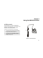
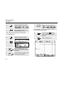
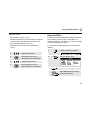
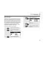
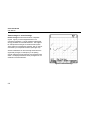
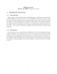
Fluke 192/196/199
MS 190 and MA 190
Users Manual Supplement
4822 872 00979
April 2000, Rev.2, 9/00
© 2000 Fluke Corporation. All rights reserved. Printed in the Netherlands.
All product names are trademarks of their respective companies.
Table of Contents
Chapter
1
Title
General.................................................................................................................... 1-1
About this Manual .....................................................................................................
Safety Information.....................................................................................................
Limited Warranty, Limitation of Liability .....................................................................
About the MS 190 .....................................................................................................
Factory Installed MS 190...........................................................................................
MS 190 Package for Field Installation........................................................................
MA 190 Accessory Kit ...............................................................................................
2
Page
1-1
1-1
1-1
1-2
1-2
1-2
1-4
Using the MS190 Function...................................................................................... 2-1
mAs Measurements ..................................................................................................
Extended Offset........................................................................................................
Persistence ..............................................................................................................
Smart Average..........................................................................................................
Non Interlaced Video Triggering ................................................................................
Variable Input Sensitivity ...........................................................................................
2-1
2-3
2-6
2-7
2-10
2-11
Chapter 1
General
About this Manual
This manual supplement is an addition to the Users
Manual that is included with the ScopeMeter 192/196/199
test tool kit.
It provides user information about the extended test tool
functionality that becomes available after installation of the
MS 190 software.
Safety Information
Read and comply with the safety instructions that you find
in the ScopeMeter 192/196/199 Users Manual that is
included in the test tool kit shipment.
The MA 190 kit accessories are intended for low voltage
(42 Vpk) use only, and do not comply with the voltage
rating on most other ScopeMeter accessories. Carefully
read the warning below which is an explicit addition to the
general accessory and ScopeMeter safety statements.
Warning
To avoid electrical shock or fire, do NOT
connect the following accessories to voltages
more than 42 Vpk (30 Vrms) or circuits of
more than 4800 VA :
• CS 190-1R, 1 Ohm shunt resistor
• TR 190-50R, 50 Ohm terminator
• TA 190-50R, 50 Ohm terminator / 10:1
attenuator
Limited Warranty, Limitation of Liability
Read the Warranty and Limitation of Liability statements
that you find in the ScopeMeter 192/196/199 Users
Manual that is included in the test tool kit shipment. These
statements also apply to the MS190 and MA190 kits.
1-1
Fluke 192/196/199
User Manual
About the MS 190
The MS 190 software expands the Fluke 190 ScopeMeter
software functionality with mAs measurements, non
interlaced video triggering, smart averaging, adjustable
persistence, variable oscilloscope input sensitivity, and
extended offset. To exploit the full potential of the MS 190
software the MA 190 accessory kit is available.
The MS 190 is either factory installed for specific products,
or can be field installed in the full series of the 190 series
products.
Factory Installed MS 190
If the MS190 has been factory installed, the type plate
shows the text “MS 190 Installed”, as shown in the figure
below.
The contents of the shipment includes:
• the ScopeMeter Test Tool kit provided with the MS 190
software extension. For the contents of this shipment
see the Unpacking instructions in the ScopeMeter
192/196/199 Users Manual.
• User Manual Supplement MS 190 (this booklet)
• The MA 190 Accessory kit.
MS 190 Package for Field Installation
The MS 190 software kit enables a Fluke 192/196/199
ScopeMeter Test Tool to be upgraded with the MS190
software functionality.
The MS 190 package includes:
FLUKE
made in Holland
9444 901 99011
No DM88888888
MS 190 Installed
1-2
• CD-ROM to install the MS 190
• User Manual Supplement MS 190 (this booklet)
• Sealed envelope containing registration code and
installation instructions
General
MS 190 Package for Field Installation
IMPORTANT NOTES (field installation only)
For Servicing it is very important that you attached the
registration code sticker on the back of your instrument.
1
Instructions for field installation
The Registration document included in the sealed
envelope provides detailed installation instructions. Prior
to installation you must register at our internet site
www.Fluke.com/ScopeMeter.
Requirements:
FLUKE MS 190 software extension
Serial Nr.: SN22222222
Reg.code : RC141414141
• Fluke 192/196/199 ScopeMeter with software version
V03.00 or higher.
Note
For later reference write your Registration Code (RC .....,
included in the sealed envelope), User Code (UC....
received after registration on the internet), and
ScopeMeter serial number (DM....... on the back of your
instrument) in the boxes below.
Earlier versions of hardware and software can be
upgraded by Fluke authorized service centers.
The service center will ask a fee and will ask you
for the registration number of your MS190 kit.
The upgrade includes a full calibration. Ask your
service center for a quote.
• PC with Windows 95/98 or NT4.0, CD-ROM drive,
RS232 serial port, and Internet access
RC
UC
DM
• Optically insulated serial cable PM9080/001 as included
with S versions ScopeMeter. It is also available as
separate accessory.
1-3
Fluke 192/196/199
User Manual
Note 1
MA 190 Accessory Kit
The MA 190 is an optional accessory kit that provides
optimal connectivity in medical and video applications.
Optimal user convenience and application coverage is
obtained when the kit is used with a Fluke 192/196/199
that has the MS 190 installed.
Before use carefully read the WARNING on page 1-1.
The CS 190-1R, the TR 190-50R, and the
TA 190-50R are not available as individual
accessory, but only as part of the MA 190 kit.
Note 2
The mAs and extended offset functionality are
available only when the MS 190 software is
installed.
The kit contains:
• TR 190-50R, 50 Ohm BNC feed-through terminator for
video and HF measurements (Max. 5 V) . See Fig. 1-1.
• TA 190-50R, 50 Ohm 10:1 attenuator feed-through
terminator for additional dynamic range and offset. See
Fig. 1-1.
• CS 190-1R, 1 Ohm current shunt for sensitive current
and mAs measurements. (Max. 500 mA) . See Fig. 2-1.
• Safety designed 50 Ohm BNC cable with isolated plastic
connectors. (1.5 m)
VIDEO
SIGNAL
SOURCE
50Ω BNC CABLE
TR190-50R
or
TA190-50R
• Female BNC to male 4 mm banana plug adapter
• Two female to female 4 mm banana plug adapters
ST8723
Figure 1-1. 50 Ohm cable termination using the
TR190-50R or TA190-50R
1-4
Chapter 2
Using the MS190 Function
mAs Measurements
50Ω BNC CABLE
The MS190 allows you to make mAs (milliampere x
seconds) cursors measurements. You can do this on live
waveforms, frozen waveforms (HOLD), recorded
waveforms, and on saved waveforms.
To perform mAs measurements, do the following:
CS190-1R
1
Connect the current shunt CS190-1R to input A
using the BNC cable (see Figure 2-1)
2
Connect the current shunt resistor CS 190-1R to
the current source using the BNC to banana
adapter (see Figure 2-1)
S T 8 722
BLACK
RED
I out
I in
Figure 2-1. mAs measurement
2-1
Fluke 192/196/199
User Manual
3
Display the INPUT B key labels.
4
Press to highlight OFF. Observe
that Input B is turned off.
Only in single channel mode key F3 allows the
T 1/T mAs selection.
5
Display the INPUT A key labels.
6
Open the Probe on A menu.
7
Select Current with the arrow
keys, then press ENTER to jump to
Sensitivity.
8
Select for example 1 V/A with the
arrow keys, then accept.
9
Display the cursor key labels.
When Voltage is selected in the Probe on A menu, the
F3 label shows mVs (not mAs)
10
Press to highlight . Observe
that two vertical cursors are
displayed.
11
Press to highlight mAs.
Figure 2-2. mAs measurement screen
2-2
Using the MS190 Function
2
The screen shows :
Extended Offset
• Top left reading, A (mA, µA, etc.):
the difference between the current amplitude measured
on the left cursor and measured on the right cursor:
The MS190 extended offset function enlarges the vertical
trace positioning range for input A and input B to 16
divisions (maximum). This allows you to zoom-in vertically
to study small details of the signal.
• Top right reading, mAs (As, µAs, etc.):
the integrated current over the time between the
cursors.
12
Highlight the left cursor.
13
Move the left cursor to the
desired position on the waveform.
14
Highlight the right cursor.
15
Move the right cursor to the
desired position on the waveform.
To choose the extended offset range for input A do the
following:
1
Display the INPUT A key labels.
2
Open the INPUT A menu
3
4
(2x)
Jump to Offset range.
Select Extended and accept the
extended offset range
2-3
Fluke 192/196/199
User Manual
Oscilloscopes and dynamic range
To move the trace:
1
Move the trace up or down until
the ground marker hits the top or bottom grid line.
When moving down, the following banner will show up:
To prevent waveforms from being distorted, in particular
signals with large very steep edges, the signal should stay
within the dynamic range, just as with any Oscilloscope.
The dynamic range limits are the same as the trace offset
limits given in the section Specifications below.
In practice you must take care when using high time base
speeds when looking at signals that have large very steep
edges. They can be distorted when they jump from
outside the dynamic range directly to the visible area of
the screen.
Figure 2-3. Extended offset banner
When moving up a similar banner shows up.
2-4
Figure 2-4 shows a pulse wave within the dynamic range
(left), and a pulse wave that is partially outside the
dynamic range (right). The example, particularly the
16 div trace offset, applies to one of the 4 most sensitive
ranges.
Using the MS190 Function
Extended Offset
2
Triggering
+8
The extended offset range allows you to shift the signal up
and down. Be aware that only the “visible” part is sampled
by the ADC, and that the trigger level has to stay in the
visible area too. Depending on what you are looking for, it
might be required to switch to Edge Trigger or to
time-qualified Pulse Trigger mode.
Tip for video signal measurements
To gain full profit of the Extended Offset for video signal
measurements:
• use the 50 Ω 10:1 attenuator feed-through terminator
-16
• select Probe on A attenuation 10:1
Avoid this for
steep edges
• select range 500 mV/d
Now you can move the trace down for 16 divisions.
Trace offset limits (= dynamic range)
Ground marker position example
Specifications
Maximum trace offset with respect to center screen:
Figure 2-4. Max. trace offset lowest ranges
Vertical ranges 5 mV to 50 mV/div (direct 1:1):
positive going signals ....................................... -16 div
negative going signals ...................................... +8 div
Other vertical ranges:
positive going signals ......................................... -8 div
negative going signals ...................................... +8 div
2-5
Fluke 192/196/199
User Manual
Persistence
5
Select one of the persistence
options and jump to Display
6
Select Dot-join or Dots only.
Accept the selection and close
the menu.
Use persistence to select the display time of the upper and
lower boundaries of dynamic waveforms. Use persistence
also to display color modulation and color burst shapes.
To select persistence, do the following:
1
Display the SCOPE key labels.
2
Open the Waveform Options
menu.
Dot join
The choice between Dot-join or Dots only depends on
your personal preference for the waveform representation
on screen, or in documentation.
3
Jump to the Waveform field.
4
Open the Persistence menu
2-6
Using the MS190 Function
Smart Average
Smart Average
Most users do not like to use averaging as the standard
default mode. Occasional deviations in a waveform just
distort the averaged waveshape , and do not show up on
screen clearly. When a signal really changes, for instance
when you probe around, it takes quite some time before
the new waveshape is stable. With smart averaging you
can quickly probe around, and incidental waveform
changes like a line flyback in video show up on screen
instantly without distorting the main signal.
To smooth the waveform, do the following:
1
Display the SCOPE key labels.
2
Open the Waveform Options
menu.
3
Jump to the Waveform field.
4
Open the Average menu
5
Select Smart
6
(2x)
2
Accept the selection and close
the menu.
2-7
Fluke 192/196/199
User Manual
Smart average vs. normal average
Normal average smoothes the waveform of repetitive
signals. It gives you the averaged waveform over
successive acquisitions. A single waveform that deviates
strongly will affect the smoothed waveform. This happens
for example when looking at an interlaced video system.
The fly-back line can distort the waveform, and you will not
see it flash by as a separate waveform (See Figure 2-5).
Another characteristic of normal average is that when the
signal really changes, for example if you are probing
around, it takes some time before the new signal becomes
stable. The displayed waveform slowly changes from one
waveform to another waveform.
Figure 2-5. Normal Average
2-8
Using the MS190 Function
Smart Average
2
Smart average gives you the primary waveform, but
displays an incidental trace of different waveshape directly
and without affecting the primary waveform .
You can now for example look at the averaged waveform
on an interlaced video system, and still see the fly-back
line flash by (See Figure 2-6).
When the signal changes are of more permanent nature,
the averaging algorithm automatically restarts and
displays the new waveform instantly, without displaying
the distorted intermediate waveshapes.
Figure 2-6. Smart Average
2-9
Fluke 192/196/199
User Manual
Non Interlaced Video Triggering
6
Select Non interlaced to open the
Scan rate menu
7
Select the required Scan rate and
confirm the selection.
To select triggering on a non interlaced video signal, do
the following:
1
Apply a video signal to the red input A.
2
Display the TRIGGER key labels.
3
Open the Trigger Options menu.
Trigger problems
4
Select Video on A to open the
Trigger on Video menu.
5
Select positive signal polarity for
video signals with negative going
sync pulses.
2-10
The non-interlaced trigger circuits expect synchronization
pulses that comply with standard video, or that are of
similar amplitude but with shorter pulsewidth. The circuit
however covers most other “standards” too. In case of
incidental problems you always can define the trigger
conditions in more detail using the time qualified pulse
triggering.
Using the MS190 Function
Variable Input Sensitivity
Variable Input Sensitivity
4
Open the Input A Options...
menu.
5
Select and accept Variable.
2
The variable input sensitivity allows you to adjust the
sensitivity continuously, for example to set the amplitude
of a reference signal to exactly 6 divisions.
The input sensitivity of a range can be increased up to 2.5
times, for example between 10 mV/div and 4 mV/div in the
10 mV/div range.
To use the variable input sensitivity, do the following:
1
2
Apply the input signal
Perform an Auto Set (AUTO must
appear at the top of the screen
An Auto Set will turn off the variable input sensitivity. You
can now select the required input range. Keep in mind
that the sensitivity will increase when you start adjusting
the variable sensitivity (the displayed trace amplitude will
increase).
3
Display the INPUT A key labels.
6
(2x)
Exit the menu.
At the bottom left of the screen the text A Var is
displayed in gray.
Selecting Variable will turn off cursors and automatic input
ranging.
7
Press mV to increase the
sensitivity, press V to decrease
the sensitivity.
2-11